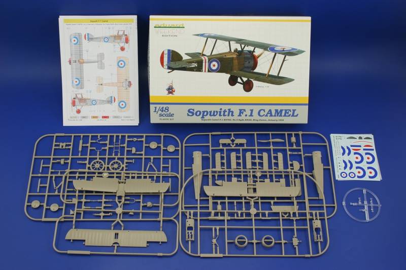
This build will be aimed specifically at the Eduard Weekend kit #8450. This kit was awaited with high expectations since it was first mentioned by Eduard representatives at the 2000 IPMS Nationals in Dallas Texas. After the first attempt at creating viable drawings they wisely decided to Go back and try it again. Their second set of drawings became the basis for this kit. The detail is all that we have come to expect of Eduards current production standards. Suffice it to say out of a possible 10 I would give it a 9.5. This is a great kit! The Sopwith model kits always require a little more effort than most other WW1 single seat fighters. With the Sopwith kits notably you will have a top wing that should look like it comes in 3 sections. Doubled RAF wire rigging at half of the locations between the wings and extensively more rigging on the Empennage (tail unit.) Comparatively the Nieuport 17 is much easier to rig than the Camel. Begin with basic clean up and pre-drill all strut locator and rigging holes. Note as you remove parts from the trees for painting or use, try using a flex file to rid your self of any unsightly mold seams. I will also use a flex file to scuff up any potential union joints as this gives the glue surfaces a little stronger bite. PP= plastic part.
The Build,
Page 2.) Shows the pilots right fuselage side ( PP A 2) interior and adds some structures ( B 12 & 17.) You can use a linen colour base for the wood and fabric areas. Then stain the wood ribs and ply with the Testors brown #1166. You may also want to thin out the interior face areas (in both fuselage halves ( PP A 1 & 2) where the control cables will enter the fuselage. This will show a scale thickness for fabric. Also you may want to thin out the forward edge to the fuselage cowling area as this area is to match the wing vent for the exhaust and if left unattended it creates an edge that doesnt look scale. (IPMS Judges will use this to disqualify an entry.)
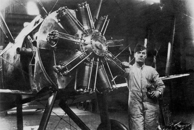
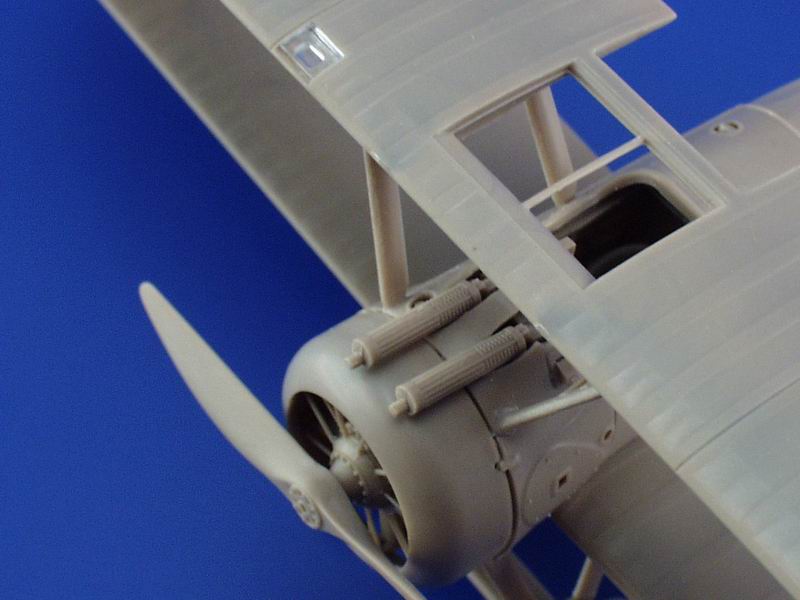
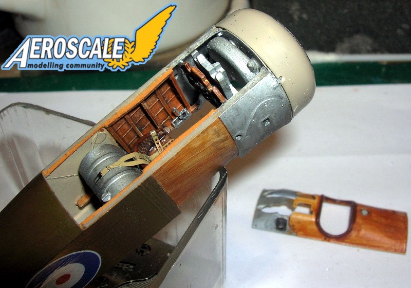
Now begins with the assembly of the Clerget type 9B rotary engine. Everything hangs on the basic engine (PP B 23.) You can substitute the plastic pushrods on the face plate covers ( PP B 15 & 22 )with brass rod for better scale effect. Also, the engine support shaft ( PP B 16) is glued into the rear of the rotary then passes through the firewall and a simple retainer ( PP B 21) is provided to glue to the shaft end. Im not too concerned with having my rotaries free floating or able to turn. For those of you that see this as a viable option try this; Make sure the shaft will pass completely through the retainer. That is the hole for the retainer should go completely through but dont add it yet. Insert the motor/shaft assembly part way through the firewall. Add a very small amount of petroleum jelly to the shaft between the firewall and the back of the rotary. Next completely insert the shaft. On the rear face of the firewall next to the shaft apply another small amount of petroleum jelly. Finally add the retainer and then apply a small amount of thin consistency cyano- glue to the tip of the exposed shaft tip with the retainer in place. The left and right wings of the firewall vent (PP B 30 & 37.) Next mount the oil tank ( PP C 7.) Also firewall wing ( PP B 30) will need a little more blending to the firewall after its attachment. The plastic is soft and easy to work with.
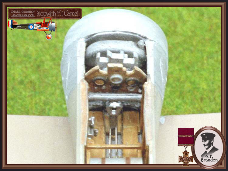
The instrument panel ( PP C 11) is detailed well and references can be found in the Sopwith Camel Datafile #26 on page 20 to their identities. They are top center, manufacturers nameplate, middle center , compass and inclinometer, center left Rev counter (tachometer), right center speedometer, far left bottom leading magneto, next to that is the trailing magneto, center bottom is the altimeter, then at right is the watch, and at far right on the bottom is air pressure gauge and relief valve. The only thing you might want to add is the pulsometer at the panels far lower left corner. The instrument panel ( PP C 11) face itself can be painted to represent Copal varnished wood.. Again I use Testors brown 1166. This is a small bottled flat that when thinned and applied as a wash stains well. (Hint: The slightly stiffer the bristles on your brush the better the wood grain effect you can achieve, just dont scrub the base coat too hard.)
The ammunition box and empty link chutes ( PP C 8) attaches directly to the back of C 11. The rear machine gun brace ( PP B 4) has a locator slot in the face of C 11. I chose to replace this piece with bent metal rod. Check your references. The carburetor intake pipes ( PP B 11) also has a mounting slot in the face of C 11. The rudder bar ( PP B 28) attaches to the base support of C 11. Later you will need to add fine wire to represent the rudder control cables. Next you assemble the hand fuel pump ( PP B 24) , seat ( PP B 38) or (PP B 27 & 36 ) and fuel tank (PP A 5, 13 & B 13) to their cradle/support frame ( PP B 5.) In the scrap view for the fuel mixture control mechanism ( PP B 32) should have a linkage scratch built for the throttle quadrant ( PP B 35.) Note here if your thinking about adding the usual fuel lines and accessories small gauge solder is usually a good choice of materials. It bends easily, takes cyano-glue well and its the right colour.
Page 3.) Add scratchbuilt lap harness straps here. Then unite engines, firewall, instrument panel, seat, fuel tank and fuselage sides. Dont forget to add some representative cable/ wire for the controls an interior structure bracings. Blackened brass wire is a good choice for this use. I also added a blackened brass wire to the tail skid ( PP B 3) for better support.
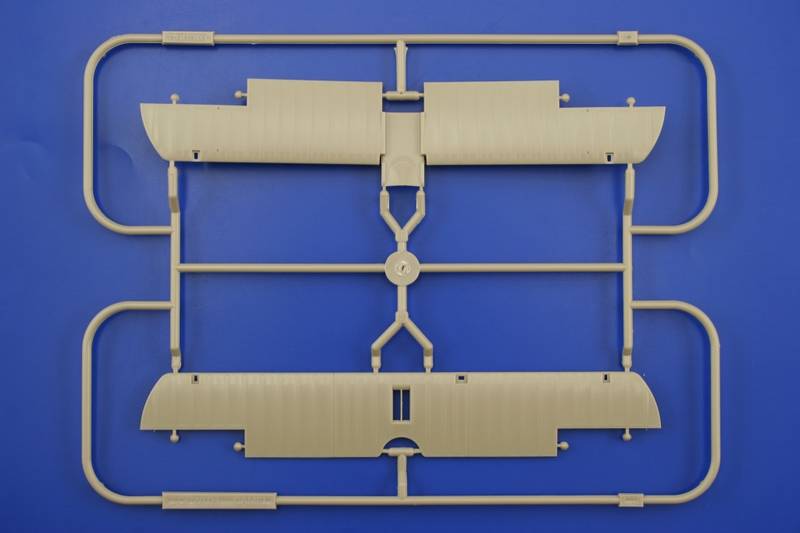
Next the lower wing (PP D 1), ailerons (PP A 7 & 11), cockpit floor and control column assembly and why Eduard gave us ten ailerons is because of the way they were molded the first time. It might have led to the wrong ailerons being attached in the wrong directions.
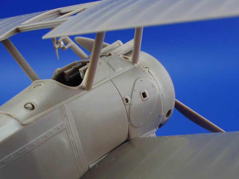
Page 4.) Note the emergency / auxiliary fuel tank (PP B 10 ) application to the cockpit turtle deck and gun cowling ( PP C 2 or 7.) The empty shell ejector chute ( PP B 34) is represented by a plastic stub to be added here. There is also a choice of two cowlings. One for a Clerget type rotary (PP C 9) with a small vent and one for the LeRhône type rotary (PP B 10) with out any vent. In scale drawings the Clerget adds about 1 3/4" to the overall length of the standard F.1 type. Later many of the LeRhône cowlings had additional vents added to their 4 and 5 Oclock positions due to the exhaust valve opening later in the cycle than the Clerget that had the single vent at the 7 Oclock position. Check your references. The instructions try to simplify the concern and show C 10 as one you can modify to a Clerget type if you drill your own hole. Also, the Clerget cowling fillet ( B 6) doesnt fit well with out some sanding of its mating surfaces for the Clerget cowling (PP C 9.)
Unite the fuselage, lower wing and engine cowling assemblies, horizontal (PP A 15) and vertical (PP A 10) stabilizers and gun breeches (A 8 X 2.) I drilled holes in the breeches to accept brass pins that will also attach to the gun jackets ( PP A 14 X 2) in the next step. As a side note I usually have to trim down the inner lip of the fuselage halves that receive the engine firewall. Otherwise I have a raised edge that juts out from the pilots left side.
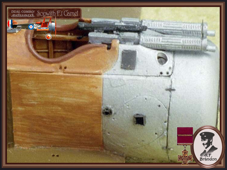
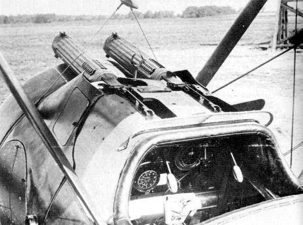
Page 5.) Attaches the Vickers machine gun vented jackets ( PP A 14 X 2.) I painted the gun assemblies with a base coat of aluminum then add a wash of black that darkens the over all look of the pieces. Vickers machine guns were bare metal but the finish was not bright metal. This also makes a great contrast to the cowling if your going with a polish cowling type. There are some photoetch detail parts that apply to specific aircraft profiles in the step along with some nice general details that just enhance the forward side cowlings.
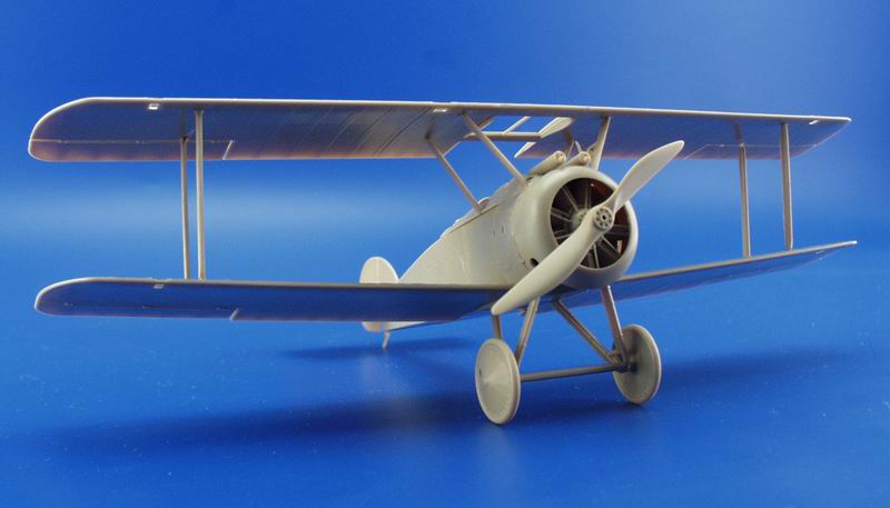
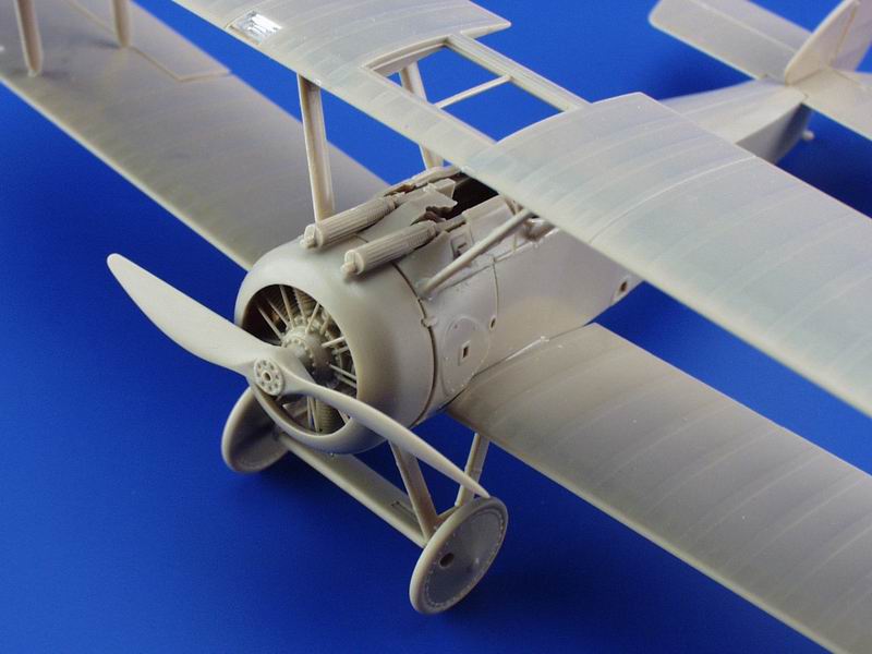
To mount the top wing (PP D 1 or 2) try using a temporary jig of childrens Lego blocks. I would add the outer struts ( PP B 9 X 2 & 19 X 2) first and get the wing plumb then go back and test fit the cabane struts ( PP C 3 - 6) to keep everything lined up. For more strength in the attachments of the interplane struts you can use brass wire or rod inserted into pre-drilled holes in the struts. The exposed ends of the wire can be inserted into the drilled out locator holes. Dont force a strut to go in place as it can throw the wing alignment off greatly. The scrap view shows the Rotherham pump located on the rear starboard cabane strut ( PP C 6.) Check your references as this was variously seen on the forward leg cabane and the forward lang gear legs as well. (See Datafile #26, page 28.)
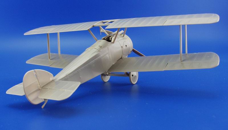
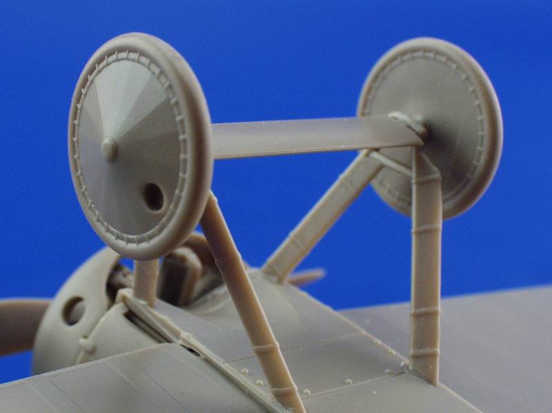
Page 6.) Next is the landing gear ( B 2, 18 & 20), wheels ( PP C 8 X 2 or PP C 26 X 2) rudder (PP A 9) and elevator (PP A 3) assembly. The landing gear ( PP C 18 & 20) items represents the types that had wood fairings over their steel tube structure. Some airframes simply had the streamlined steel tubing.
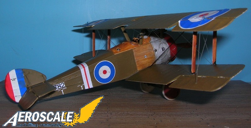
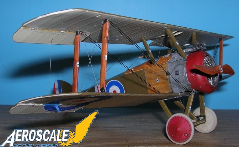
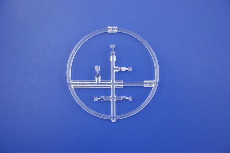
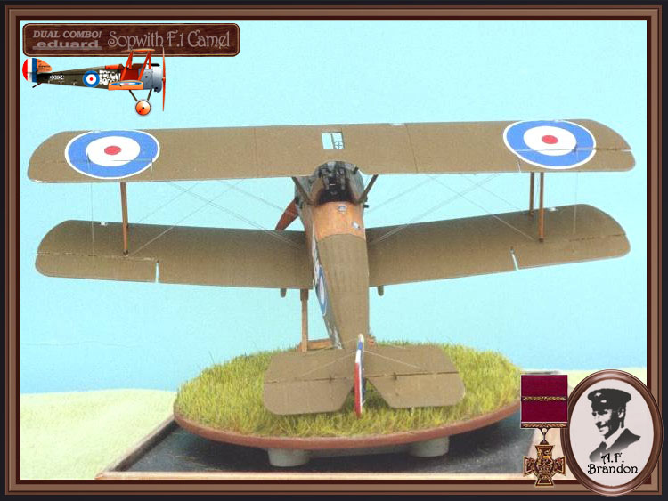
Page 7.) Shows the under & upper surface rigging patterns and the propeller (A 4) attachment. Several types of propellers were employed on F.1 types. Theyre presence evidently did not indicate with engine type that was installed in a given airframe. Most of these British propellers had a coating of red-brown shellac and the wood grain was not apparent. Check your references. Add your own windscreen.
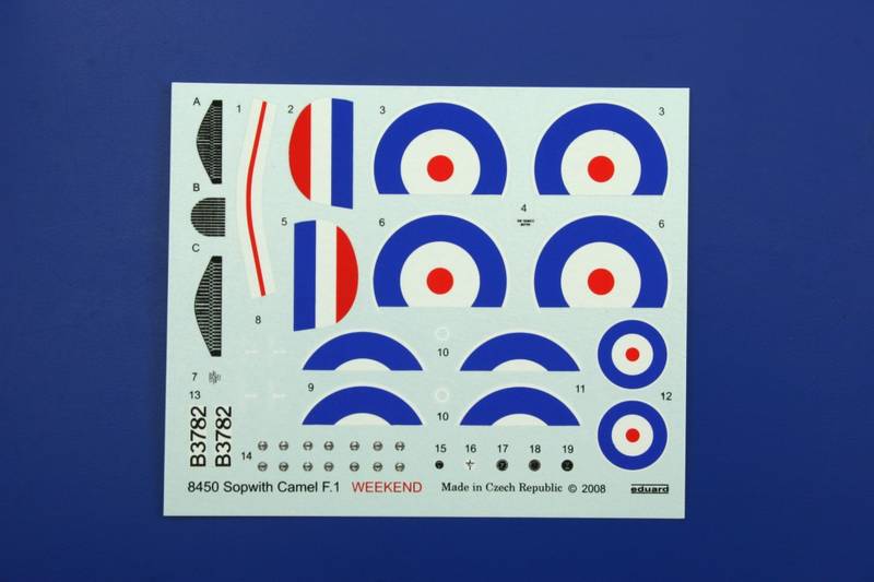
Decals,
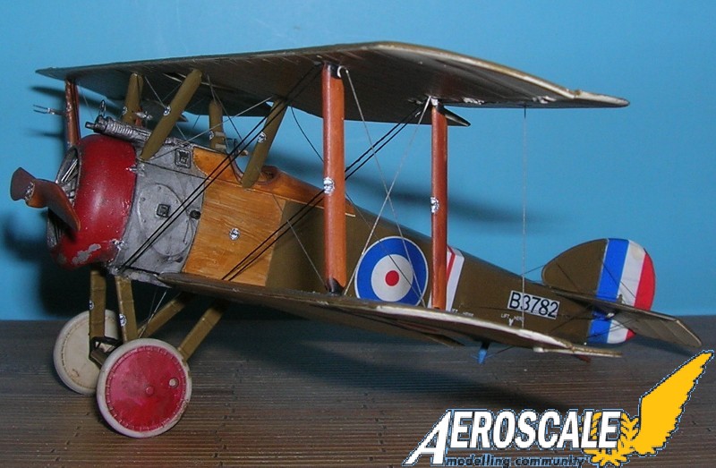
Eduard Weekend kits only gives you one set of decals. This one is for the Sopwith Camel F.1 B3782 was flown by Lt. L A Breadner, No.3 Sqdn RNAS,during Sept. 1917.
References,
Barker & 139 Sqdn I.E.F. by R.C. Johnson, IPMS Rocky Mtns Pp.8-9, May 1996.
Colour Profiles of WWI Combat Planes by Apostolo & Bignozzi, Crescent pub. Pp.33-40, 1974.
Four Aces by Doris Reeves, IPMS Sounders-Erhart Pp.126-7 Circa 1972.
General Arrangement Drawings of the F.1 & 2F.1 (printed in 1/48 Scale) by W.R.Titus, Cross & Cockade USA , Vol.7 #1, Pp.81-92, 1966.
Sopwith Camel, PAM News Intl. Pp641-646, February 1979.
Sopwith Camel by J.M.Bruce, Windsock Datafile 26, Albatros Publications, 1991.
Sopwith Camel Aces of World War I by Franks, Osprey aircraft of the aces #52, 2003.
Sopwith Camel - King of Combat, by C. Bowyer, Aston Pub. Ltd. 1988.
Sopwith Fighters by J.M. Bruce, Vintage Warbirds #3, Arms & Armor Press, 1986.
The Legendary Sopwith F.1 Camel by Ray Rimell, Scale Models Pp.509-511, October 1978.
The Camel Drivers by Otis Lowell Reed George Roland, Schiffer Books, 2005.
The Sopwith Camel F.1 by J.M.Bruce Profile #31, Profile Publications 1965.
Highs: The detail is exactly the high lervel we have come to expect from eduards excellent design team.Lows: Minor fit problems around the fuselage firewall area can be easily overcome. Eduard should do a detailed Bentley rotary to go along with the RNAS & RAF Camel issues.Verdict: Easily this is the best 1/48 kit of this type to date.Eduard has repackaged a good kit using minimal investments in additional artwork. The up-side for them is stock reduction with more profit. We all win.
Our Thanks to Eduard! This item was provided by them for the purpose of having it reviewed on this KitMaker Network site. If you would like your kit, book, or product reviewed, please contact us.
About Stephen T. Lawson (JackFlash) FROM: COLORADO, UNITED STATES
I was building Off topic jet age kits at the age of 7. I remember building my first WWI kit way back in 1964-5 at the age of 8-9. Hundreds of 1/72 scale Revell and Airfix kits later my eyes started to change and I wanted to do more detail. With the advent of DML / Dragon and Eduard I sold off my ...
And still a few more.
This is the end of the tail. . .er uh tale. My thanks to Rowan (leave my wand alone) Baylies and to the generous people at Eduard for the review kit.
Greetings Roxter;
Yes, I will put one of the Eduard1/48 British figures with it when I put it in the case. Though I was toying with one of the Mark Copplestone jobs. . . for a moment. The "fork is the airspeed indicator. Pretty common om most BEF aircraft.
Excellent work as always, Stephen. I have two of these to build.
Do you know of any pictures of the clear wing inspection panels from an actual Camel?
Mark
Wonderful Job done Stephen ! The whole project is very eye catching with the weathering job done and just love that wood grain . Thank you for sharing the review of the build with us kind kinder folk !
Building a Bentley rotary for the Naval versions is relatively easy. But you need a bigger item than the kit Clerget verion. Brass rods are stay pins. white metal represent push rods.
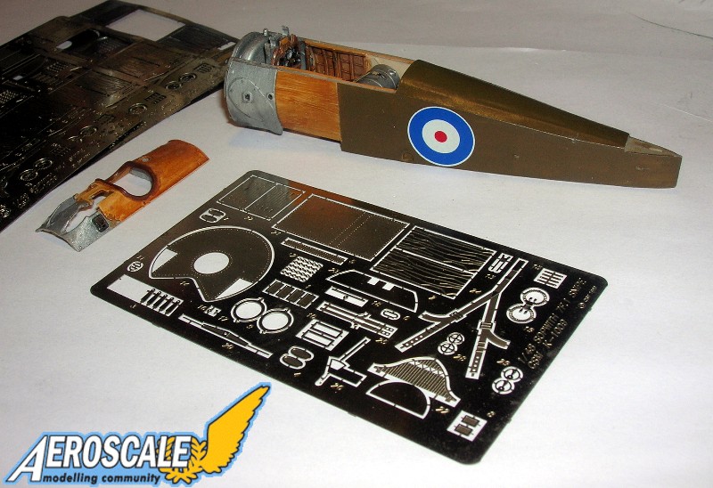
From the Como build thread. The PE seen here is not in the Weekend basic kit.
From the Como build thread. The PE seen here is not in the Weekend basic kit.
From the Como build thread. The PE seen here is not in the Weekend basic kit.
From the Como build thread. The PE seen here is not in the Weekend basic kit.
From the Como build thread. The PE seen here is not in the Weekend basic kit.
From the Como build thread. The PE seen here is not in the Weekend basic kit.
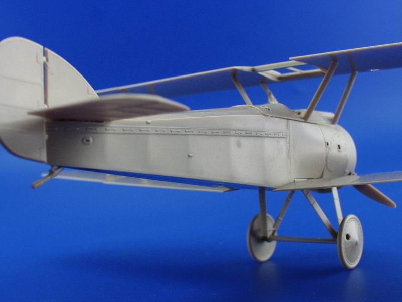
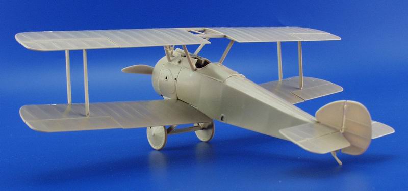
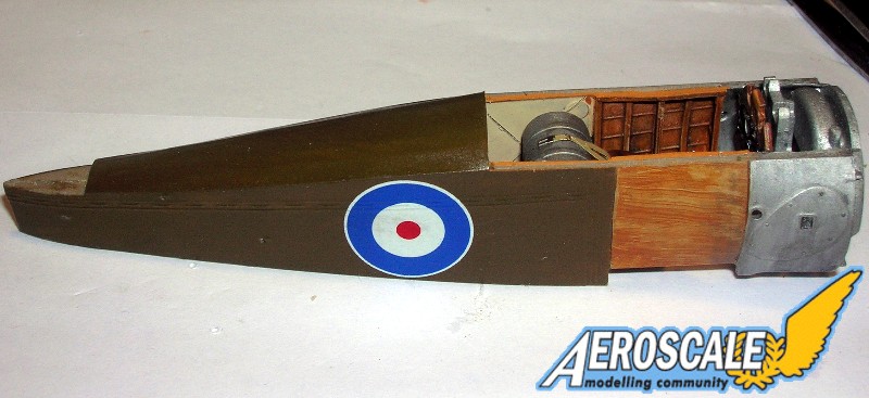
Plastic kit with larger center section cut out.
Plastic kit with larger center section cut out.
Plastic kit with larger center section cut out.
Plastic kit with larger center section cut out.
Plastic kit with larger center section cut out.
Plastic kit with larger center section cut out.
Plastic kit with larger center section cut out.
Plastic kit with larger center section cut out.
Plastic kit with larger center section cut out.
Plastic kit with larger center section cut out.
Plastic kit with larger center section cut out.
Plastic kit with larger center section cut out.
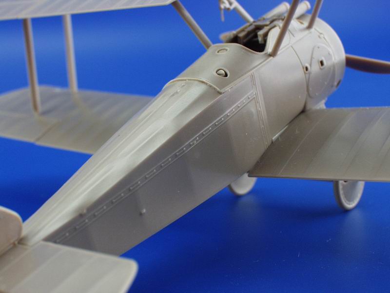
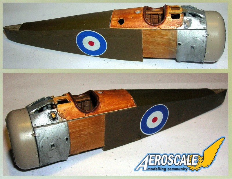
Fuselage
Fuselage
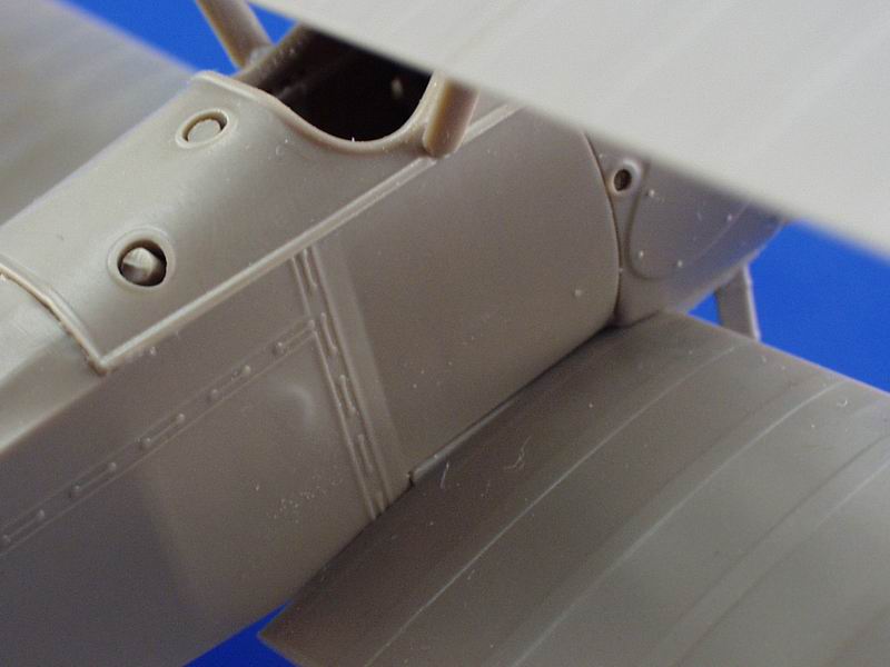
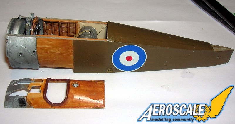
Eduard fuselage with Copper State modeles parts.
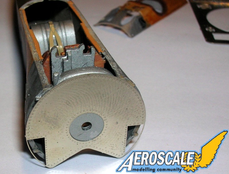
Here the Copper State Models PE firewall has been added.


Comments