

1⁄48In the line of Fire
Historical perspective,
The Halberstadt CL.II was the first deliberately designed aircraft for the ground attack role. In 1917 Halberstadter Flugzeug Werke company began producing the Halberstadt CL.II. It was designed to provide air support for ground troops. With three machine-gunsGround attack is a close relative to tactical bombing. It is aimed at disrupting enemy forces at or near the front and during the course of the battle itself. While strategic and tactical bombing raids are planned and directed at specific targets, ground-attack is often carried out against targets of opportunity, as they appear on a changing battle-field. It is carried out by strafing and by dropping small munitions such as hand grenades. Ground attack is carried out from very low altitudes and is thus both extremely accurate and extremely hazardous.
During the Battle of Messines, in June of 1917, British air force commander Hugh Trenchard ordered the British pilots to fly low over the lines and strafe whatever targets presented themselves. This was in order to harass the troops and break their morale. During the Third Battle of Ypres which followed, this tactic was further pursued and developed with Sopwith Camels armed with four 9kg (20 lb) bombs raiding enemy trenches and approaches. While effective, the loss rate of the attacking planes was very high.
At about the same time the Germans took delivery of the Halberstadt CL II. This was a two seater tractor aircraft intended originally as an escort fighter for observer planes. Realizing the effectiveness of direct ground attacks, flights of Halberstadt CL IIs were reorganized into attack flights (Schlachtstaffeln).
These planes were better equipped for ground-attack duties than the single-seater Allied fighters, which were particularly vulnerable to attack from above and behind, while the pilot was preoccupied with aiming and strafing. In the Halberstadt the observer provided both warning and some level of protection from such attacks, and could assist by dropping bombs or grenades. . .
The Halberstadt Cl.II grew from a request by Idflieg in November of 1916 for a light C class aircraft powered by the proven Mercedes 160hp engine. Halberstadt rolled out a prototype in April of 1917 and after modifications were made, primarily concerning increased wingspan to provide greater lift, Idflieg signed a production contract for 100 examples in May of 1917. The first aircraft started reaching the front in late July of 1917 and by September of that year Kogenluft (commanding general air services) released a report which stated that combat experiences to date had shown universal front-line acceptance of the CL.II in the protection, ground-attack and two-seater fighter roles. Approximately 900 examples were ordered with the peak front-line inventory reaching 342 machines in April of 1918. Although supplanted by the CL.IV model in its production, the CL. II soldiered on alongside its successor in the Schustas and Schlastas till the end of the conflict with many examples finding service with the air forces of other nations after the war.
Multimedia kits,
The subject of this article is the Blue Max Limited Edition kit in 1/48 scale. This kit first appeared in 1998 but because of its limited production run of 1500, it's no longer available from most hobby venues. However, examples can still be found on some internet sites and I can imagine that I have outbid, and been outbid by, some of the modelers who are reading this article.The Blue Max kit contents,
The Halberstadt CL.II kit parts are made from styrene plastic and white metal with hand printed decals on a very thin carrier film, no photo-etch or resin is included. Also, there is a strip of material furnished to produce the inter-plane struts, but I'm not really sure what this is made of. There is a guide on the instruction sheet for all the lengths that are needed but there's not very much left over once cutting is complete. I had very limited material left to test glues with. It turned out that cyanoacrylate will do just fine. I tried liquid cement and it seemed to work but I went with the Zap a Gap. What you get for assembly instructions is a basic exploded view drawing which shows the various pieces floating, as if the kit was blown up and the pieces started to fly away from the center. It gives the modeler some idea of their placement but when the glue starts to hit the plastic and metal, you're going to want something a little more definitive. More on that later. The instructions do provide you with notes on the coloring, or colouring (hello Merlin), of the various parts, placement of the markings and tips on lozenge orientation and camouflage patterns. Unfortunately, there are no lozenge decals included with the kit, which at the present time leaves the modeler with very few options. More on this later.My Perspective,
I build my kits primarily out of the box. One of the reasons for this is my skill level at the present time. Another is the time factor, I like to complete my builds in a reasonable amount of time so that I can keep a descent rate of production. Adding lots of aftermarket can sometimes slow the wheels of progress, so for me super-detailing and tons of aftermarket products does not always find its way in to my builds. This is not a reflection on those that build in this manner. On the contrary, I have the utmost respect for modelers who use these products and the results they achieve.The Build,
Onto the actual construction of the kit. Building this kit is kind of like a scratchbuilding project with the best exception being that all the different pieces have already been furnished for you. The modeler just has to figure out how to assemble them and in what sequence. This is where your reference material plays a pivotal role. I can't recommend enough picking up a copy of Windsock Datafile #27. This 36 page booklet is the Rosetta stone with which you can decipher this riddle. Manufactorer Chris Gannon states in the copy of the instructions that this Datafile and its drawings were the primary resource for creating this kit. It will help you with placement of the interior and exterior parts, alignment and attachment points for the wings to the fuselage, with the proper spacing of the inter-plane struts and the angles of the wings in relation to each other and the fuselage.Chapter one,
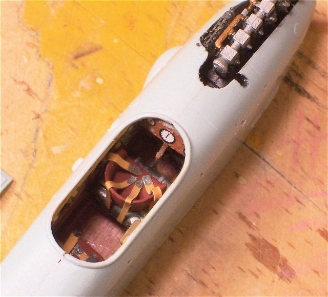
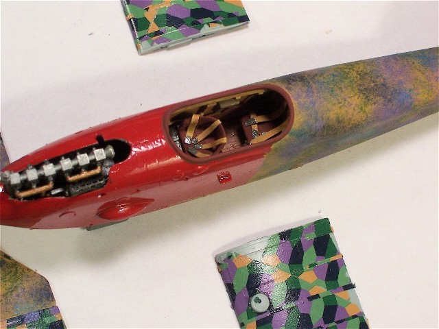
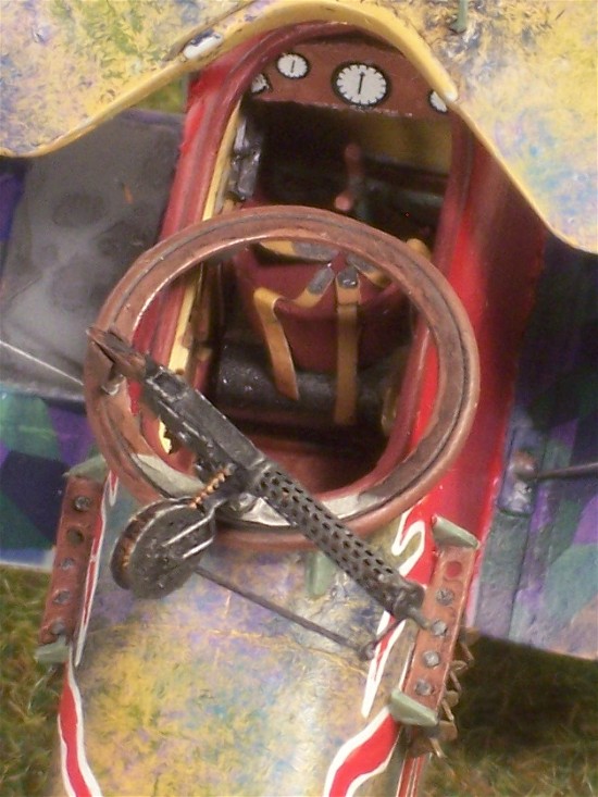
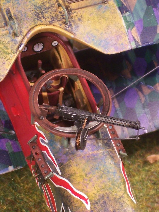
I found that construction follows pretty much along the lines of newer injection molded kits. The limited run nature of the kit does show up in a number of ways, though. The modeler must give the plastic parts a bath as there is more than the usual amount of mold releasing agent on the plastic parts. There is a fair amount of flash encountered, both on the metal as well as the plastic pieces. Low pressure molding also means that the sprues are very thick with resulting heavy attachment points to the pieces. This complicates the clean-up process as the kit exhibits some very nice detail throughout, especially on the wings with a taut fabric condition and delicately depicted raised tapes. I recommend some delicate hobby knife work, finishing up with small metal files for the final shaping.I assembled the interior first along with the engine and this is where the Datafile pays off right away. There are no alignment pins and sockets or location marks in the fuselage halves here so consulting with the Datafile is essential. The fit of the metal and plastic pieces is fairly good with some sanding being needed here and there. Prepainting of some of the pieces is necessary here as well. One thing the modeler will wrestle with while assembling the interior will be placement of the forward Maxim machine gun. Some surgery will be needed here and you will need to thin the fuselage wall where it will protrude. One of the few times I went with some aftermarket for this kit was here where I used an Eduard photo-etch cooling jacket for this machine gun. After the interior bits and engine are all painted and put in place its time to dry fit the fuselage halves. Don't expect Eduard precision here. A fair amount of sanding and scraping will be required as well as some scrap wedges placed into some of the resulting gaps. Using regular testors plastic cement I glued only the forward part of the fuselage together and let it dry. I worked my way towards the tail, gluing the fuselage halves together in three different stages. Everything pretty much lined up well. After the halves are together there is quite a bit of sanding with some filling to make everything nice and even but on the whole there was less than I expected.
Chapter two,
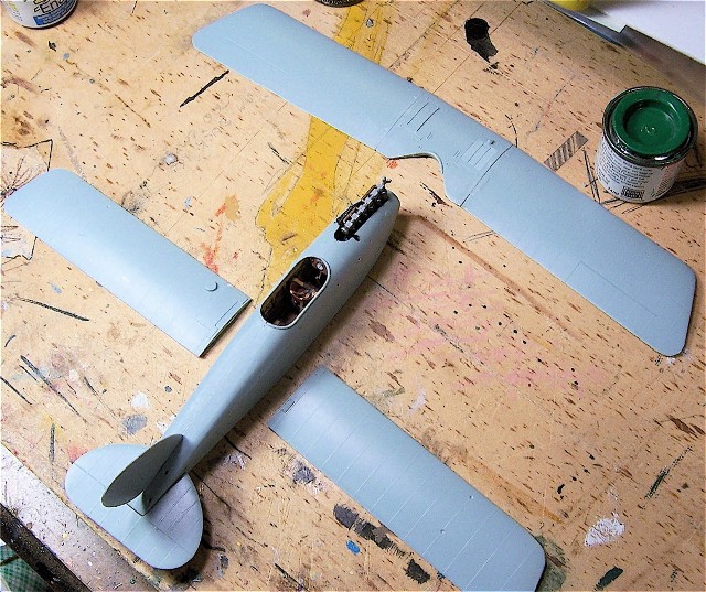
Once the fuselage halves are together its time to play with the wings. In this stage we will construct the upper wing, apply the decals to the top and bottom wings and then attach the bottom wings to the fuselage. Datafile time! The upper wing is in 3 pieces, all of which are plastic. The pin drill and wire reinforcing rods need to came out for this part. One of the first things you'll notice on the overhead drawing in the Datafile is the swept-back nature of the top wing. The kit parts are accurate in this regard and match up well to the drawings. The central part of the wing is covered with plywood and contains the radiator and a fuel tank so this will be painted with the camouflage scheme on the top and with a varnished appearance on the bottom . There is no dihedral in the upper wing so laying it flat on the drawing was good. I then used a straight edge like a small triangle and drew with a pencil two perpendicular lines across the seems where the wings and center piece meet. Do this for each side. This pencil mark is then continued onto the inside flat surface of the wing where its glued to the central part, from top of the wing to the bottom. Perform this for all three pieces of the top wing.This line marks where I will drill to reinforce and true the alignment of the full wing. I use a drill bit thats slightly larger in diameter than the wire to allow for some adjustment if needed and drill corresponding holes in all three pieces of the top wing. Zap a Gap was used to adhere the wire into the holes on the wings and then thats set aside to dry. The bottom wings have the only slot and grove alignment features provided with the kit. I still checked the alignment with the Datafile to make sure the kit ones were accurate. Lines were drawn again to assure alignment. The holes were drilled and the above process was repeated. Going back to the top wing, I used Zap a Gap on the ends of the wire protruding from the wing and inserted them into the central part, do this for both sides and then check to see if they match the swept-back angle of the Datafile illustration. If so then lay them on a flat surface, no dihedral remember, and then run the seems with liquid cement to melt all three together. Let this set overnight.Chapter three,
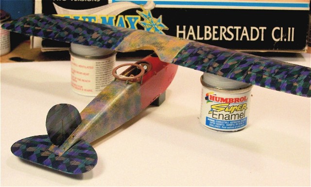
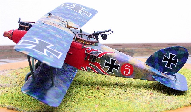
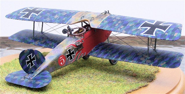
Lozenge. I was able to salvage some in progress pictures I had taken to send to a fellow wingnut while I was building this. The thread listed below as well as JackFlash's Lozenge 101 thread here on Aeroscale's Early Aviation title should provide all the information you will need to accurately apply the lozenge to this aircraft. I used the 5 color set printed by Techmod of Poland, set number 48030. The pattern shapes are fairly accurate and the bottom shades are close but the top colors could use a bit of help. To help in this matter I used Future Floor Polish tinted with artists acrylic colors. The colors are Ultramarine blue and Burnt Sienna brown. The strips of lozenge are placed at 45 degrees instead of cord wise and the pattern has to be flipped around so that like edges face each other. Tapes were made from thin sliced strips of the upper color. I made them double cord length so that they would wrap around the upper and lower wings. This saved on quite a bit of time and I know Stephen has mentioned this being done on his lozenge thread and he's provided some photographic conformation of the practice. I 'm not sure if Halberstadt or their subcontractors did it this way. The fin/rudder and stabilizer/elevator were covered in lozenge as well but without tapes per Dan-San in the Aerodrome thread. After everything had set overnight it was time to tame the psychedelic Techmod upper lozenge. I mixed some Future with Ultramarine blue first, the ratio is about 20 to 1. Even though both mediums are acrylic they are not necessarily compatible. Not all manufacturers use the same formulas in making their acrylic bases so don't be surprised if the artist color curdles in the pool of Future, persistent and thorough mixing will do the trick. I recommend that you apply this mixture to some scrap plastic or an old shelf queen to test its tinting ability before applying it to the lozenge surfaces. Once you're happy with the mix, apply it to the lozenge using a cord wise brush pattern and let it dry thoroughly, which for the Future should be anywhere from 20 minutes to an hour. I then add the Burnt Sienna to this mix and apply it to the top surface only. If you look at the accompanying photos you will see the difference between the original appearance and the tinted final product. There is an added benefit in that the cord wise application of the tinting medium gives the lozenge a textured look that mimics the nature of the fabric.Back down to the bottom wings, no matter how much I tried I could not use the molded on slot and grove features of the lower wing joint as they prevented the wing from sitting flush against the fuselage. Off they came. The above process was repeated to attach the bottom wings to the fuselage accept for the dihedral. I created a temporary jig made of old paint bottles and folded cardboard to ensure the kit didn't move and angles were maintained. After that the fin/rudder and stabilizer/elevator were liquid cemented into place with no troubles. The last thing I attached at this point was the metal cabane struts. Its at this point that the painting and decal application begins.
Chapter four the unique fuselage camouflage,
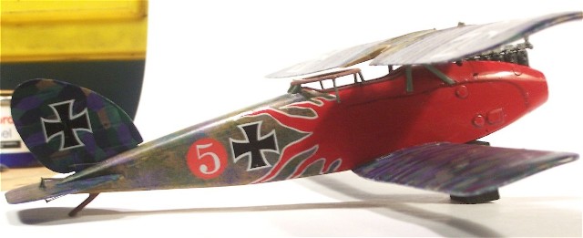
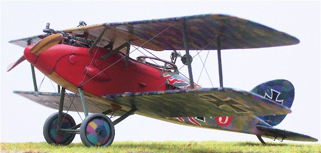
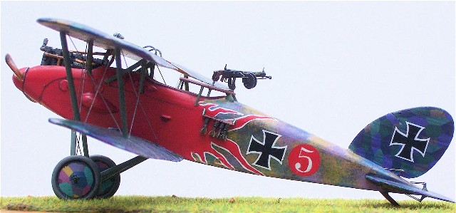
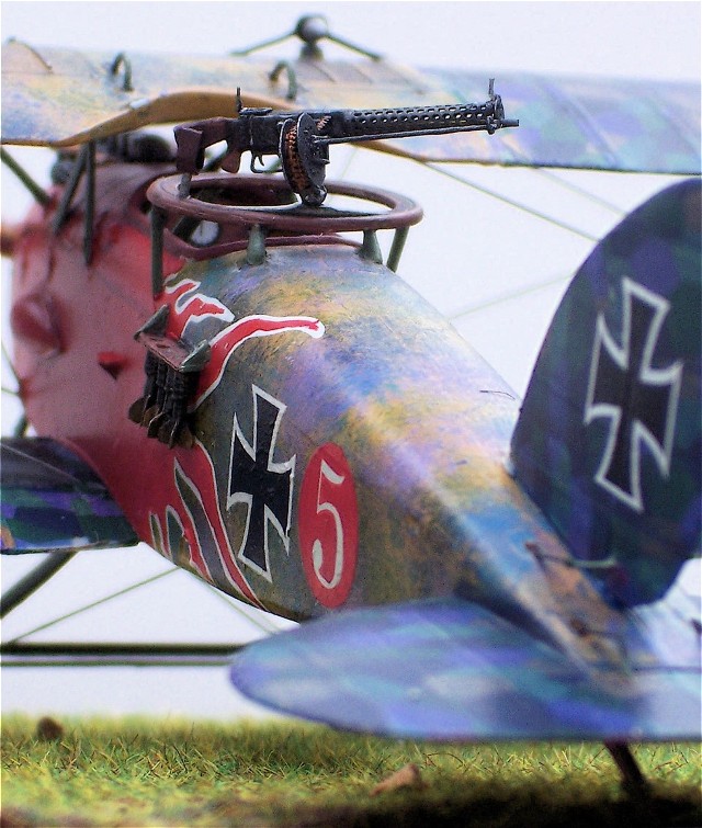
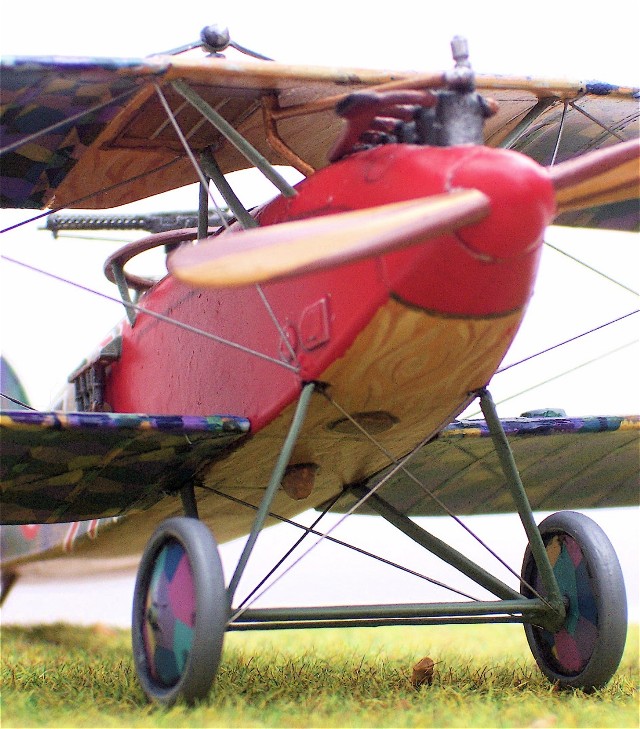
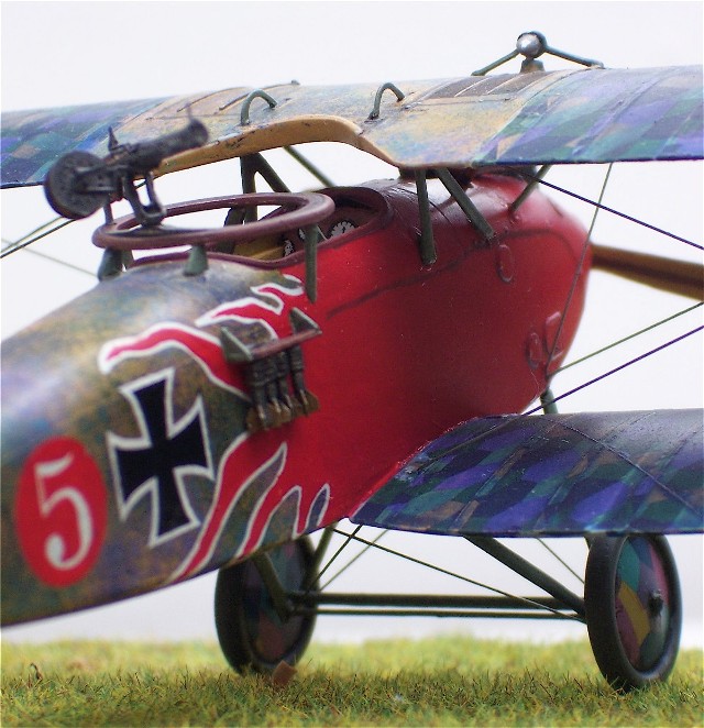
After everything had time to dry it was on to making it look like that unique camouflage scheme found on the Halberstadt CL.II. I was fortunate that I had run across this thread on another website. All the information you will need to reproduce the colors of this scheme are right here, just click or cut and paste and you're on your way. I will follow up this feature with a small picture demonstration article about how I executed the camouflage scheme. The paint used on the fuselage was primarily Humbrol enamels. I painted the fuselage with a base coat of Humbrol #63 which looks like a warm, light almost honey color of brown. Next i used a technique that can best be described as a form of dry brushing for dappling the camouflage. I used an older chisel brush to apply the colors. For those who are not familiar, a chisel brush is one that is shaped like the end of a metal hand tool called a chisel that is used in woodworking. The bristles are short and the ferrule, or metal cap holding the bristles, is flat and wide. Dip the brush into the color and wipe most of it off onto scrap paper leaving enough on the ends of the individual bristles so that they no longer stick together. I then dab the end of the brush against the surface, I do not drag it at all. This produces the tiny dots of color on the surface. Don't be afraid to repeatedly dab the brush against the surface and also vary the pressure you use as well. If too much camouflage color gets on the surface you can dapple some of the base color on top of that when it dries so you need not panic if mistakes occur. I used two greens,#78 and #30, two blues, #48 and #198 and Testors ModelMaster #2013 Napoleonic Violet with Humbrol #19 to slightly warm it up. decided to apply the fuselagedecals at this point because there appeared to be color compatibility issues with the red I used on the forward fuselage and the red printed on the kit decals. Sure enough, they didn't match. Out came the 000 paint brush, thinner and my Humbrol #19 red. One of the most important things to make this work is to thin the color just enough to keep most of its opaque quality but allowing it to flow uniformly out of the brush. Multiple coats were needed but the results were worth it. In one of the in progress pics you can see the difference between the red in the flames and the red of the circle with the 5 in it. After the rest of the fuselage decals were applied and were set i clear coated them with Future to protect them from damage while handling the kit.Chapter five. pilot holes for the rigging,
At this point it was time to pre-drill everything for the rigging and then assemble the rest of the kit. I use the tried and true method of drilling receiving holes in the top wing and using though holes in the bottom wing and fuselage for the mono-filament rigging material and then gluing them into place using clamps and gravity to keep them taut during the process.. This has been covered many time before in the forums posted here on the website so I will rely on the reader to do further research on the website if they are not familiar, plenty of great reading in there.Chapter six adding the top wing,
After all the pre-drilling its time to attach the top wing. Fortunately the rear cabane struts are metal and fit well in their notches on the fuselage once those notches are enlarged toward the center line. The receiver holes on the underside of the top wing line up pretty close but can be enlarged either sideways or back to front to allow for proper alignment. At this point the Datafile really pays off. You can place the fuselage on the drawing itself an test fit the top wing onto the cabane strut and adjust for the proper alignment. Some surgery may be required depending on how you constructed the kit up to this point but my example lined up really well. This is where the previously cut strut material comes in. I worked on the forward cabane strut and the forward interplane struts first and checked the length with the drawings before appying some Zap a Gap. I used the adhesive sparingly at first because I knew adjustments would be needed. Using the Datafile as a guide For clearence between the wings and the fuselage and the top wing I was able to get a satisfactory alignment without much hassle. After these struts were in place the rear inte-plane struts were installed and the alignment was compared with the Datafile until I was satisfied with that as well. This process was easier and went better than I thought it would and it didn't require a special jig, just a lot of patience.Once that top wing is on the rest of the construction follows a conventional path. The only other additions to the kit that were not in the box were some more photo-etch bits for the control wires leading to the elevator and rudder, plus a Copper State Models Parabellum M.G. for the scale observer. I scratched a travel lock for the Parabellum from plastic dowel stock and some photo-etch sprue. The landing gear axle is made from a styrene dowel and the spacer bars are brass. The rigging for the landing gear and the control wires on the tail is .008 high E electric guitar string.
Final Comments,
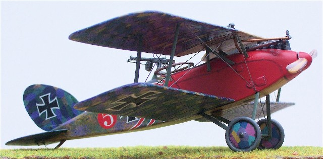
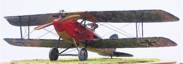
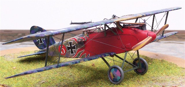
Thats it. This kit is for the experienced modeler and outside reference is a must. That said, the level of detail along with its accuracy make this a rewarding build indeed. I will probably be following this up with a small pictorial demo piece of how I accomplished the camouflage scheme. Dwayne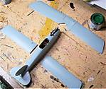 Built by Dwayne Williams from the 1/48 Blue Max kit.
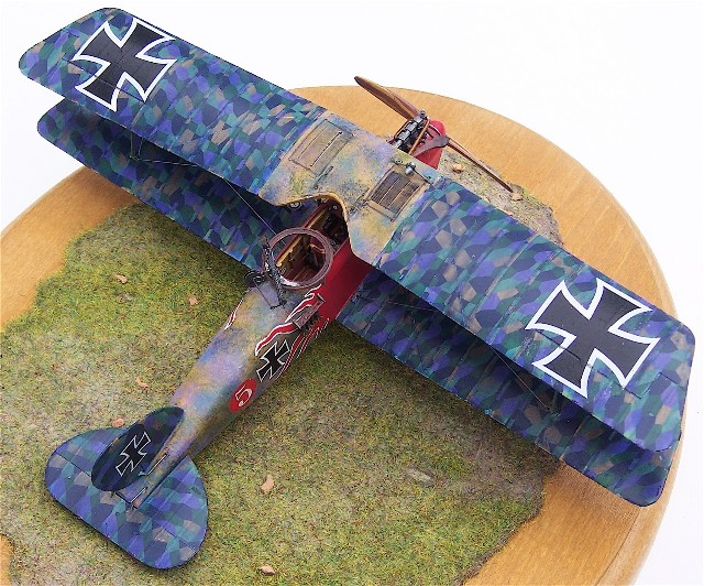
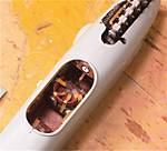 Built by Dwayne Williams from the 1/48 Blue Max kit.
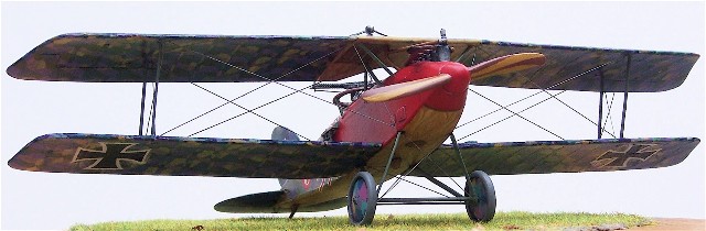
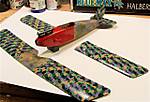 Built by Dwayne Williams from the 1/48 Blue Max kit.
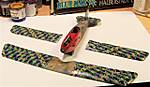 Built by Dwayne Williams from the 1/48 Blue Max kit.
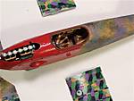 Built by Dwayne Williams from the 1/48 Blue Max kit.
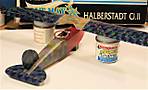 Built by Dwayne Williams from the 1/48 Blue Max kit.
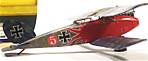 Built by Dwayne Williams from the 1/48 Blue Max kit.
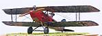 Built by Dwayne Williams from the 1/48 Blue Max kit.
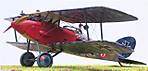 Built by Dwayne Williams from the 1/48 Blue Max kit.
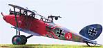 Built by Dwayne Williams from the 1/48 Blue Max kit.
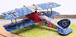 Built by Dwayne Williams from the 1/48 Blue Max kit.
 Built by Dwayne Williams from the 1/48 Blue Max kit.
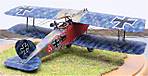 Built by Dwayne Williams from the 1/48 Blue Max kit.
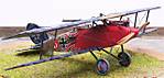 Built by Dwayne Williams from the 1/48 Blue Max kit.
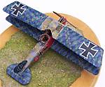 Built by Dwayne Williams from the 1/48 Blue Max kit.
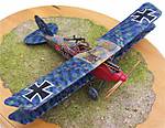 Built by Dwayne Williams from the 1/48 Blue Max kit.
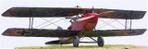 Built by Dwayne Williams from the 1/48 Blue Max kit.
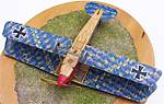 Built by Dwayne Williams from the 1/48 Blue Max kit.
 Built by Dwayne Williams from the 1/48 Blue Max kit.
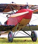 Built by Dwayne Williams from the 1/48 Blue Max kit.
 Built by Dwayne Williams from the 1/48 Blue Max kit.
 Built by Dwayne Williams from the 1/48 Blue Max kit.
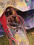 Built by Dwayne Williams from the 1/48 Blue Max kit.
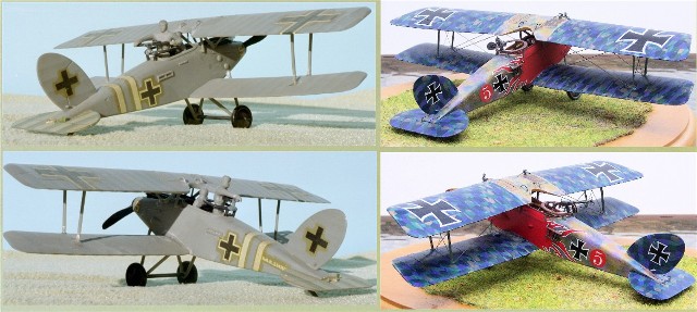
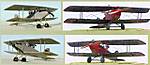 Comparison between the old Aurora kit and the excellent Blue Max mold. We have come a long way.
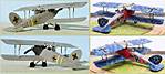 Comparison between the old Aurora kit and the excellent Blue Max mold. We have come a long way.


About the Author


Copyright ©2021 by Dwayne Williams . Images also by copyright holder unless otherwise noted. The views and opinions expressed herein are solely the views and opinions of the authors and/or contributors to this Web site and do not necessarily represent the views and/or opinions of AeroScale, KitMaker Network, or Silver Star Enterrpises. Images also by copyright holder unless otherwise noted. Opinions expressed are those of the author(s) and not necessarily those of AeroScale. All rights reserved. Originally published on: 2008-07-20 00:00:00. Unique Reads: 9776

WEB HOSTING BY


Copyright ©2021 AeroScale and Kitmaker Network, a subsidiary of Silver Star Enterprises
All Rights Reserved. Please read our Conditions of Use and Privacy Policy.
All Rights Reserved. Please read our Conditions of Use and Privacy Policy.