

P.D.U.1
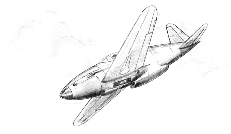
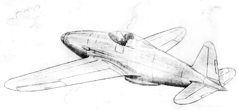
The sketches reproduced here formed part of the original 1940 proposal.
INTRODUCTION
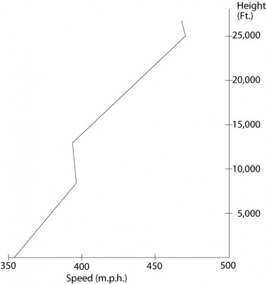
The photographic reconnaissance work carried out by the Photographic Development Unit has proved the justification for the design and production of a purely photographic aeroplane, but, at the same time, the potential usefulness of such a machine in other spheres has been borne in mind. The proposed P.D.U.1. aircraft has been planned specifically to cover the requirements of a high altitude and very fast photographic aeroplane. It can easily be adapted to a very efficient fighter, but it is here regarded mainly from its possibilities as a photographic reconnaissance aeroplane.With a maximum level speed of 470 miles per hour at 25,000 feet altitude and a range of 1050 miles at 330 miles per hour at 32,000 feet, the P.D.U.1. has a performance that will be hard to equal by any fighting aircraft for at least three years.
Overload tanks of 48 gallons increase the range to 1380 miles. The gliding distance without engine from 32,000 feet will be approximately 70 miles. The view from the cockpit is a special consideration in the design and large perspex panels in the bottom of the cockpit are fitted for downward observation. Although the design is conventional in order to make certain that a practical aeroplane with good flying qualities and moderate landing speed will be produced, the P.D.U.1. has a perfection of aerodynamic form not previously attained. No structural difficulty interferes with the shape. The undercarriage is of a new type Which permits perfect flush sealing of the wheel openings without hinged flaps, and a body-wing combination of low interference. These results have been obtained by taking full advantage of the most recent research. The ideal radiator, large in size and fully ducted, with low and possibly negative drag, is to be installed for the first time.
Standard materials, now being used in production aeroplanes in this country, are alone employed in the construction.
Adaptation of the machine as a fighter has also been given careful consideration.
ENGINE
The Rolls-Royce GRIFFON engine, though not yet in production, has been chosen, as it will be available as the best engine possible at the time when the P.D.U.1 prototypes are 70% constructed. The design of this engine is based upon the "R" engine of Schneider Trophy and record fame. The power guaranteed by Rolls-Royce for production purposes is 1445 B.H.P. at 15,000 feet. Research Is proceeding on a new blower and it i considered that the maximum power will be maintained to 29,000 feet, an improvement that has already been achieved with the Rolls-Royce RM38M engine. Advantage of the new blower has been tu n In the performance calculations of the P.D.U.1, and added to it is the effect of the forward facing intake measured on existing aeroplanes.
THE P.D.U.1. AS A FIGHTER
1. Straightforward modification would convert the aeroplane for use as a fighter.(a) Four Browning .303 guns, each with 300 rounds, or (b) two Hispano Suiza 20 m.m. cannons, each with 80 rounds in Bristol belt boxes, would reduce the top speed by 8 miles per hour, but would not add much to the weight when cameras and special equipment are removed.
(c) Heavier armament, such as four cannon guns and armouring of pilot and ammunition, would mean an increase of wing area and entail a loss in top speed of about 18 miles per hour.
2. With its larger wings, in the photographic reconnaissance form, the P.D.U.1. would have a better climb and ceiling than in its standard form, but its top speed would be reduced by 9 miles per hour.
3. The excellent view will be appreciated by the pilots of modern low-wing fighters.
4. As all petrol is carried in the wings, fire risk is considerably reduced. Self-sealing tanks could be provided at a slight weight increase.
PERFORMANCE.
ENGINE - ROLLS-ROYCE GRIFFON WITH SPECIAL BLOWER. Power - 1445 B.B.P. at 20,000 feet. With forward facing intake, power becomes 1500 B.H.P. at 25,000 feet.| Maximum speed at 25,000 feet. | 470 m.p.h. |
| Economical cruising at 32,000 feet. | 330 m.p.h. |
| Range at economical cruising in still air (without glide) at 32,000 feet. | 1050 miles. |
| Take off distance over 50 ft. screen. | 365 yards. |
| Service ceiling. | 42,000 feet. |
| Glide without engine from 32,000 ft. | 70 miles. |
| Range with overload tanks. | 1,380 miles. |
WITH THE STANDARD GRIFFON ENGINE. (1.445 B.B.P. at 15,000 ft). The maximum speed is obtained with a B.H.P. of 1500 at 19,500 feet and is calculated to be 442 m.p.h. The service ceiling is reduced to 36,000 feet.
These performances were estimated independently by technicians experienced in high speed work. In cases of disagreement, notably on top speed end range, the lower figure has been taken. The calculations of the P.D.U.1. can be taken as conservative, as they are based upon the best existing aeroplanes and l1ttle allowance has been made for the advanced aerodynamic characteristics of this design, owing to lack of reliable data.
DESIGN AND CONSTRUCTION.
The design is based on taking present knowledge into full consideration. No liberties have been taken with stress figures, nor is any structural difficulty allowed to interfere with aerodynamic perfection and a practical solution is presented for each problem.
FUSELAGE.
The fuselage form is the best known. Its
median line is curved to agree with the wing section and to
produce correct load grading spanwise.
It is constructed of alclad sheet, flush
riveted at the joints and frames. All stiffeners and
subsidiary members are spot welded to the skins before
assembly.
The frames are of plain flanged sheet and the
longerons are drawn top-hat sections. No lightening holes
are used.
The cockpit hood is of heavy perspex, rebated
flush.
ENGINE MOUNTING AND COWLING.
The engine mounting ie of German type, but
forgings are not employed. The two large beams are
built up from standard sections and the two stays are of
steel tube.
The cowling is of alclad, spot welded. It
is perfectly sealed and the cooling air for engine
auxiliaries and exhaust is ducted and controlled.
UNDERCARRIAGE.
The main and tail wheels are fully retractable,
flush and sealed.
The single cantilever oleo legs are of a new
design. Telescopic as well as retractable, they carry a
rigid fairing.
It is desired to emphasise that the use of
this type of leg contributes greatly to the efficiency of
the P.D.U.l. Its advantages over existing designs are:-
(1). The long leg is supported at the spars where
the wing has a reserve of strength for
landing loads.
(2). The use of a long leg allows the fuselage
to be of ideal form and to raise the wing
above the inefficient low wing position.
(3). The wheel fairing is rigid and structural~
part of the leg. A flush and airtight
sealing of the wheel housing is thus
achieved by the simplest means and no use
is made of questionable flaps or dangerous
mechanisms.
All present day single seaters are seriously
handicapped by undercarriage problems, which detract trail
the efficiency of the aeroplane as a whole.
ACCOMMODATION AND CONTROLS.
The pilot's seat and all flying controls are
adjustable. Control is mainly by push and pull rods.
Trimming tabs are fitted to aileron, elevators
and rudder and are under the control of the pilot.
All trimming controls and controls for engine,
airscrew, petrol cocks, etc. are Teleflex.
The machine has been designed with a pressure cabin, taking into consideration the high altitude at which it will be called upon to operate. Oxygen bottles are also to be fitted.
The view from the cockpit is superior to that of any existing single-engined aeroplane of high speed, and special attention has been paid to vision aft. Downward observation panels of perspex are fitted in the bottom of the fuselage.
TAIL UNIT.
The tail unit is designed to allow a perfect
finish for the wind and the fin is set forward for that
reason, and also to provide for recovery from the spin.
Elevator and rudder surfaces are fabric covered with
sharp trailing edges by a special method of construction.
The fin is integral with the fuselage e and the
tailplane is metal covered and detachable.
WINGS.
The wing is of the single spar type with
alclad skin flush riveted at joints and strength members.
All stiffeners, auxiliary member and door panels are
spot welded. to the kin before assembly.
The leading portion of the wing is of new construction. The forward ribs are without braces and carry an inner skin of plastic sheet which supports the fuel tanks.
Standard extruded sections, machined to a taper, form the booms of the spars. Alclad sheet with riveted stiffeners is used for the web. The main ribs are of drawn Alclad sections, braced and bolted to the spars.
Slotted and sliding flaps with flush guides are used to reduce landing speed. They are metal covered with sharp trailing edges and are sealed in the closed position.
The ailerons are provided with large differential and are sealed against all leakage. Of metal construction, they are fabric covered, but with sharp trailing edges like the rudder and elevator.
COOLING SYSTEM.
The large ducted radiator is in accordance
with the latest research. A check on the form of the
duct and the arrangement of the vanes will be made in
the wind channel during construction.
A radiator of the optimum size has never before been fitted to an aeroplane and, although it is computed that such a design should add to the forward speed, advantage has not been taken of this in the performance calculations.
Pressure water is used as the coolant. The header tank is mounted on the engine behind the spinner. A section of the radiator Is used as an oil cooler.
Access is arranged by detaching the rear portion of the fuselage.
FUEL TANKS.
The fuel tanks are of special petrol resisting
rubber in bags and are mounted and supported by plastic walls
in the leading edge of the wing. The tank space are smooth
and without obstruction by braces or members likely to chafe,
and handholes are provided in the wings to allow the tanks to
be pushed into position on or easily removed for repair.
In the event of' the P.D.U.1 being used as a
fighter, the bags would be covered by self-sealing rubber of
the linatex type.
EQUIPMENT.
The installation of the two Eagle IX or similar
cameras is immediately behind the pilot. In addition, two
F.24 cameras can also be mounted in the fuselage.
Provision for four oxygen bottles has been made.
EXHAUST.
Ducted ejector type exhaust manifolds are fitted.
Controlled cooling of sparking plugs is provided.
WEIGHTS
STRUCTURE.Wings. 700 Lbs
Engine cowling. 75 Lbs
Engine mounting. 105 Lbs
Fuselage & fin. 430 Lbs
Tail Plane & Elevators. 60 Lbs
Rudder. 20 Lbs
Tail wheel. 30 Lbs
Wheels & brakes. 86 Lbs
Chassis & retracting gear. 280 Lbs
Controls & accommodation. 120 Lbs
Total structure. 1906 Lbs
POWER PLANT.
Engine. 1800 Lbs
Airscrew. 360 Lbs
Exhaust. 28 Lbs
Accessories & piping. 110 Lbs
Radiator. 260 Lbs
Cooling system. 100 Lbs
Petrol tanks. 70 Lbs
Oil tanks & cooler. 70 Lbs
Total Power Plant. 2798 Lbs
LOAD CARRIED.
Pilot & parachute. 200 Lbs
Cameras, etc. 300 Lbs
Special equipment. 50 Lbs
Petrol, 140 galls. 1010 Lbs
Oil, 10 galls.
Total Load Carried. 1650 Lbs
WEIGHTS SUMMARY.
Structure. 1906 Lbs
Power Plant. 2789 Lbs
Load Carried. 1650 Lbs
Margin for Estimate. 146 Lbs
TOTAL. 6500. Lbs
LOADINGS.
Wing area (gross) = 200 sq. ft.
Wing loading = 32.5 Ibs/sq.ft.
Power loading = 4.33 Ibs/h.p.
About the Author


FROM: NO REGIONAL SELECTED, UNITED KINGDOM
I have an interest in photographic reconnaissance, in particular the Photographic Development Unit based at Heston at the beginning of WWII.
Comments


All Rights Reserved. Please read our Conditions of Use and Privacy Policy.