German Secret Projects of WW2 Vol. 6
2
Comments
Hi again.
Thanks to commitments both on the home and work fronts, this volume has taken much longer than expected. In fact it’s probably one of the biggest gaps since I started doing these profiles. However it is quite extensive and as usual it’s a mixture of completely reworked profiles and brand new ones.
The specification issued by the Technical Air Armaments Board (Technische Luftrüstung) in late January 1944 included requirements: Top speed of 900 kph (559 mph), Endurance of 4 hours, Armament consisting of four cannon. Internally mounted radar (FuG 240 or 244).
Vogt based the BV 215 on the P212 single jet fighter, featuring a short fuselage, with the air intake in the nose directly feeding the two Heinkel He S 011 jet engines tucked away in the rear fuselage. It shared a common feature of Vogt’s Blohm & Voss designs, in that the fuselage structure was built up around the intake tube, with all components attached to this structure. The wings were of 30 degrees sweep and 6 degrees of dihedral, with the outer wing tips angled down at 23 degrees. The nose landing gear from the Heinkel He 219 was used. A large variety of armaments could be housed in the nose. Construction was mostly of metal with wooden control surfaces and nose. The performance would have been good but missed the specification’s requirements. Even so, the RLM selected it for further development, but the war’s end brought all work to a halt.
The P.252/2 illustrated here, had quite a long fuselage, with a crew of three housed in a pressurised cockpit. The pair of Junkers Jumo 213J 12 cylinder liquid-cooled engines with MW 50 boost, were housed in tandem powering an extension shaft to drive two 3.2 meter (10' 6") contra-rotating swept 3 blade propellers through a cruciform tail.
To feed the engines, circular air intakes were located in the wing roots and on both the starboard and port sides of the fuselage.
The cruciform tail design had the added advantage that the bottom fin also served as a tail protector to stop the propellers from hitting the ground on takeoff. The P.252 design allowed for a formidable armament in the nose along with an internal radar dish.
In spite of the official specification requiring power by turbojets the P252 fared very well with many advantages, including excellent visibility, heavy armament and good endurance. However it represented the absolute limit of conventional piston engine technology which left little, if any, room for further development, whereas the jet engine promised much, much more. So, mainly due to this fact all further work on the Do P.252 design was reluctantly abandoned.
This was powered by a He S 021 turboprop, located within the fuselage just behind the cockpit. The jet engine was fed by two air intakes located in each wing root similar to the twin boom ‘Flitzer’. The mid fuselage mounted wing was swept back 31 degrees, and the tail planes were also swept back. A tricycle landing gear arrangement was fitted. Armament was to be a single MK 103 30mm cannon firing through the propeller hub and two MG 213 20mm cannon in the lower forward fuselage.
Profile Notes: I’ve done some profiles of the aircraft as the plans, but have also included some of a hypothetical marine development.
Thanks to commitments both on the home and work fronts, this volume has taken much longer than expected. In fact it’s probably one of the biggest gaps since I started doing these profiles. However it is quite extensive and as usual it’s a mixture of completely reworked profiles and brand new ones.
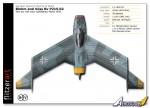
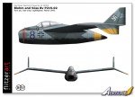
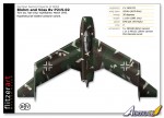
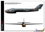
Blohm and Voss BVv P215 Night fighter
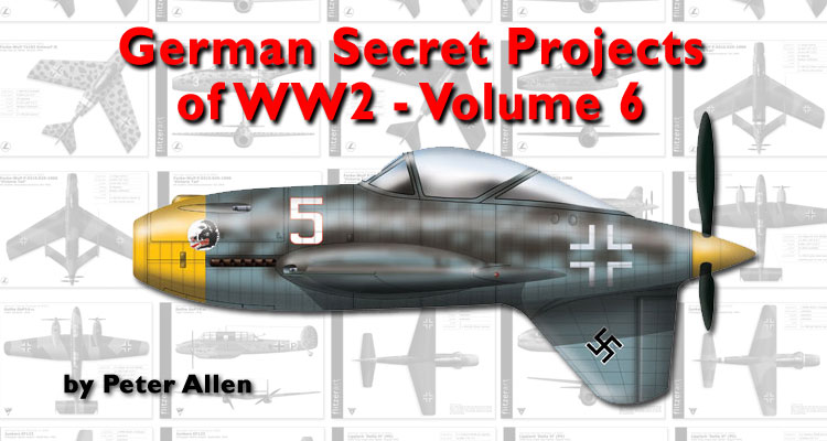
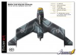
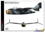
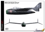
After designing the BV 212 in late 1944, Dr. Richard Vogt, quickly began work on an aircraft to meet the RLM specifications issued for a new night fighter.The specification issued by the Technical Air Armaments Board (Technische Luftrüstung) in late January 1944 included requirements: Top speed of 900 kph (559 mph), Endurance of 4 hours, Armament consisting of four cannon. Internally mounted radar (FuG 240 or 244).
Vogt based the BV 215 on the P212 single jet fighter, featuring a short fuselage, with the air intake in the nose directly feeding the two Heinkel He S 011 jet engines tucked away in the rear fuselage. It shared a common feature of Vogt’s Blohm & Voss designs, in that the fuselage structure was built up around the intake tube, with all components attached to this structure. The wings were of 30 degrees sweep and 6 degrees of dihedral, with the outer wing tips angled down at 23 degrees. The nose landing gear from the Heinkel He 219 was used. A large variety of armaments could be housed in the nose. Construction was mostly of metal with wooden control surfaces and nose. The performance would have been good but missed the specification’s requirements. Even so, the RLM selected it for further development, but the war’s end brought all work to a halt.
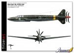
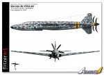
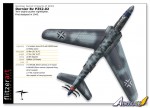
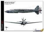
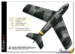
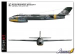
Dornier Do P252.02 Night fighter
Originally designed in 1943, the Dornier Do P.252 was submitted for the optimum Luftwaffe night fighter contract specification from January 27, 1945. Three similar design studies (P.252/1, /2 and /3) were carried out, only differing slightly in dimensions, intake positions and wing plan forms.The P.252/2 illustrated here, had quite a long fuselage, with a crew of three housed in a pressurised cockpit. The pair of Junkers Jumo 213J 12 cylinder liquid-cooled engines with MW 50 boost, were housed in tandem powering an extension shaft to drive two 3.2 meter (10' 6") contra-rotating swept 3 blade propellers through a cruciform tail.
To feed the engines, circular air intakes were located in the wing roots and on both the starboard and port sides of the fuselage.
The cruciform tail design had the added advantage that the bottom fin also served as a tail protector to stop the propellers from hitting the ground on takeoff. The P.252 design allowed for a formidable armament in the nose along with an internal radar dish.
In spite of the official specification requiring power by turbojets the P252 fared very well with many advantages, including excellent visibility, heavy armament and good endurance. However it represented the absolute limit of conventional piston engine technology which left little, if any, room for further development, whereas the jet engine promised much, much more. So, mainly due to this fact all further work on the Do P.252 design was reluctantly abandoned.
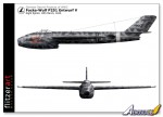
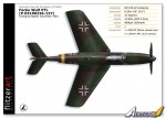
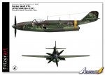
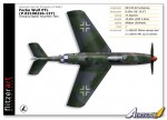
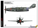
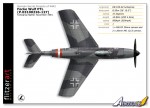
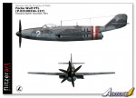
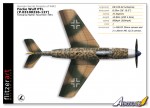
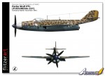
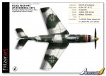
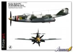
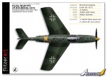
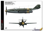
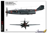
Focke Wulf PTL (P0310226-127) Turbo-prop Fighter
Numerous design studies were done around what is generally known as the ‘Flitzer’. These included the more well-known twin boom mixed propulsion fighter and an earlier turbo prop powered version. After design assessment, it was found there may have been high speed issues with the ‘Flitzer’s tail arrangement’, so Focke Wulf penned a further design following a more conventional tail layout.This was powered by a He S 021 turboprop, located within the fuselage just behind the cockpit. The jet engine was fed by two air intakes located in each wing root similar to the twin boom ‘Flitzer’. The mid fuselage mounted wing was swept back 31 degrees, and the tail planes were also swept back. A tricycle landing gear arrangement was fitted. Armament was to be a single MK 103 30mm cannon firing through the propeller hub and two MG 213 20mm cannon in the lower forward fuselage.
Profile Notes: I’ve done some profiles of the aircraft as the plans, but have also included some of a hypothetical marine development.
Comments
Thanks for a great article Peter. I know how long these profiles take!
Incredible that the P1110 was designed 65 years ago, and yet wouldn't look out of place if it had been submitted alongside the YF-22 and YF-23.
MAY 15, 2010 - 11:10 AM
Many thanks Rowan, Jean-Luc and back room staff for doing the hard work in getting it up and running.
Thanks Ben.
In many cases I think the designs were so far advanced there was little chance of making them work then. The situation was one of needing technology to catch up to make a success of them which is possibly why so many look bang up to date even today in many respects.
More in the prep shop.
Peter
MAY 16, 2010 - 07:33 AM
Copyright ©2021 by Peter Allen. Images also by copyright holder unless otherwise noted. The views and opinions expressed herein are solely the views and opinions of the authors and/or contributors to this Web site and do not necessarily represent the views and/or opinions of AeroScale, KitMaker Network, or Silver Star Enterrpises. Images also by copyright holder unless otherwise noted. Opinions expressed are those of the author(s) and not necessarily those of AeroScale. All rights reserved. Originally published on: 2010-05-15 00:00:00. Unique Reads: 23701


