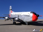
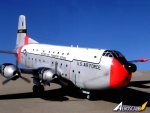
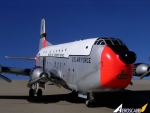
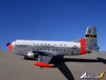
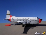
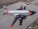
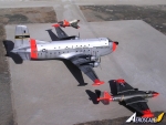
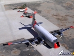
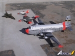
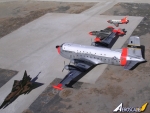
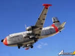
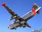
1⁄72Douglas C-124 Globemaster
1
Comment
The build
The Kit: Douglas Globemaster Kit No 211Make: Airmodel
Scale: 1/72
Price: cost of kit 18 Euro, cost of u/c legs: 16.5 Euro, cost of Anigrand decal sheet: 8.5Euro
Comments: Large vac-form kit in white soft acetate, no undercarriage, and no decals but with accurate scale plans and good illustrated instructions.
The kit
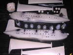
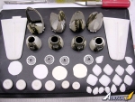
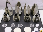
The kit is a vac-form type and comes in two large sheets in white acetate and a smaller one in clear thick acetate containing the cockpit canopy. The 22 “ X 16.5 “ instruction sheet printed on both sides contain detail scale plans and an exploded view that is good for reference during assembly. There are line drawings of the propeller, nose and main landing gear, upper deck floor with detail cockpit crew office all of which enable you to assemble components made from scratch built parts. Drawings also indicate painting detail of the upper surfaces of the nacelles and wing areas. Upon opening the kit polythene bags the kit looks impressive in view of its enormous size with a bulky fuselage at the scale of 1/72. There are four half parts for each engine cowling and nacelle combination. These appear crude in appearance and addition there is the front part of the radial engine. There is a certain amount of surface details on most parts, which were used as a guide for further detailing. The impressed marks of the many portholes allover the fuselage sides appeared to be in their correct place and of correct size. The kit was also measured and found to be correct in both length and span.General comments
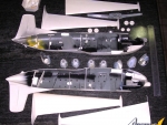
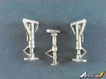
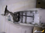
Perhaps one of the observations that one makes on the kit parts like the rudder, tail fin, elevators, ailerons and wing trailing edges is the presence of lumpiness that is common in early vac-form kits. However this proved to be of no difficulty as these areas could be scraped with a knife blade after sanding down the kit parts.The kit contains 10 major items that includes the main wings, fuselage parts and tail planes. Besides there are central sections and bulkheads that are shown in the explodes views. These essential items are not among the kit parts so that one has to make the scale drawing of the bulkheads and then cut them from the spare backing sheet. I used plasticine (silly putty) to obtain the section contour and make my own partial bulkheads at different stations along the fuselage. I had no intention to detail the cargo hold since any detail added would be barely visible through the portholes. The 6-wheel bogie being split horizontally into two sections and there was loss of hub detail that needed refining by carving using a pointed E-xacto blade. A tool that proved to be handy for checking a vac-form kit of this size was an outside caliper. This was used to check the width of fuselage while sanding down the large fuselage halves. One major fault with this kit is the lack of issuing an undercarriage suitable to hold the heavy and sizeable model. Scratch building one made of plastic pieces would prove to be weak as the model has to be handled tens of times during building. It is therefore recommendable to obtain a set of oleo legs made of pewter from Ross of Dallas…e-mail address is: [email protected] The fuselage halves which matched correspondingly still took a lot of filler to produce a smooth upper fuselage and hide the seam with subsequent sanding and rescribing the panel lines.
Construction
The kit build follows the normal sequence of cutting and preparing parts as mentioned in previous examples and rather than repeating same here are listed the important points useful in making a robust kit of the Globemaster which is made from relatively soft vac-form material that come with the Airmodel kit.1) Ideally use a sheet of medium grade wet and dry paper taped to a board. Trailing edges of wings and rudder were sanded to thickness required and also scraped on the outside as mentioned earlier. Panel lines were redrawn.
2) Cockpit area is cut out using scissors and the edges trimmed to shape using a file. Having prepared the fuselage halves the portholes are drilled and brought to shape with a round file. This will ensure that when bulkheads and stiffeners are fixed they will not come in the way of open portholes.
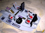
3) Interior detail should be decided at this stage. I decided to add a detailed crew office. This was made up by first building a cockpit sub assembly and when completed it is transferred to the kit for fixing in place. I drew a cockpit floor on a plastic card; on it I fixed four crew seats as per instructions. Front and side consoled, instrument panel, rear bulkhead, control wheels, rudder pedals and some other items shown on instructions were all added. To the fuselage parts I also added alternate tabs to both sides in order to self locate and secure the parts when brought together. The kit needed lead weight. Cockpit interior were painted black, gray and zinc chromate green.
4) Three plastic boxes were constructed and made in such a way to fit at the lower deck of front fuselage right under the cockpit floor. These boxes measuring 2” x ¾” square section were to hold lead pieces to balance the kit on the nose. Loose lead was encased with tissue paper and white glue and the boxes closed with glue, were then cemented to forward area close to the nose wheel well.
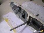
5) Other essential work to be done before closing the fuselage was to cut slots to the wing root so that an aluminum bracket that will hold the wings at the right dihedral will be inserted. The bracket, made of Aluminum measured 9.75” x 26mm wide x 3 mm thick. This can also be made of plywood. A jig was drawn from thick cardboard to hold the wing at the correct angle of 8 degrees to the horizontal and retaining the dihedral on each side while it is setting. A template made from thick cardboard will check the correct distance of the inner engine nacelles from the fuselage.
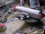
6) The engine nacelles integral with cowlings and front radial engine piece were attended to in same way as building a vac-form kit followed by rescribing the panel lines and reshaping the exhaust pipes at the sides. These are the items that needed much care when bringing them to attach to the wings.
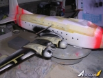
7) When assembling the wings, these had support section brackets fitted chord wise starting from a point 5” from the root i.e. away from the aluminum bracket mentioned in (5). The position of the cowlings on the wing, which were incorrectly printed on the wing, were altered and this was done AFTER the wings are attached to the fuselage. The wings were allowed to set for a day held with pegs and checked to see that the shape is retained and remains level. The wings to fuselage were another step that required checking twice or more over and the bracket that is now protruding from each side of the fuselage, is inserted in the wings at each side. With the wings in place and faired with a small amount of Filler they are strong enough to withstand handling however it was noted that the outer wings may not be strong to hold the bulky fuselage and during handling it is was safer to grip the wings from the root area from then on. A fillet at the trailing edge root area was not provided and had to be made from a piece of plastic card cut in triangular shape and fitted and faired with Plasto. The new place for the cowlings was marked using a template prepared to check the distances from the fuselage for each side of the inner and outer engines.
8)Building a model of this size and the continuous handling it entailed it is imperative to have a sturdy undercarriage and even better than plastic ones made of stretch sprue and runner parts. Best way out is to get a metal undercarriage. This can be obtained from Ross or Scale Aircraft Conversions.com
9) Before fixing the undercarriage legs it was essential to build a robust well roof and side walls. Each well is boxed and fitted securely and detail added inside allowing place where the oleo is to be fitted in the correct spot as displayed on scale plans. Interior detail was made after studies of photos of wheel well interior structures. The wheel doors were also detailed as best one could. The metal legs that fits under wing well were fixed at an angle so that they are perpendicular to the ground level.
10) I had a set of four propellers which were modified by extending each at the tip simply by adding ¼” piece of plastic card to each tip to form the 3-bladed right hand propellers. Then shaped accordingly at their tip end.
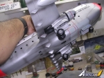
11) There are 8 servo pods, which operate the flaps and ailerons. Some aircraft had only 5, which are closer to the fuselage. I fitted all the eight pods of different size the larger ones are nearer to the fuselage trailing edge. Their place was also relocated from the position they were printed in the surface after checking with scale plans. Air intake at the rear and other surface detail items were added to the kit.
Paintwork and Decals
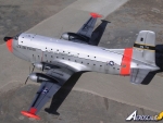
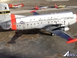
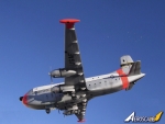
The wheel hubs were first painted silver, then masked with a round cut masking tape and painted in Acrylic black. The astrodome carried by early C-124 was replaced with a clear round skylight and treated in same manner as all the portholes. i.e. covered with Kristal Klear at the end. I also noted that the wireless did not end at the top of fin but at the lower part of the fin. The black areas were airbrushed in Revell aqua color Schwarz gloss 36107, top fuselage airbrushed in Model Master semi gloss white. The rest of the model was first masked the white and black areas and airbrushed with a mix consisting of commercial silver made by Hample (Malta) ltd, few drops of Model Master semi gloss clear lacquer and few drops of gloss white. Allowing time for paint to dry and the kit was given an overall coat of Johnson’s Klear (improved formula).Decals were obtained from Anagrand for a price but these had serial registration of a type less colorful than the one I had in mind to do and these still needed modification. Micro scale came to the rescue and I used all the cheat lines and walk way lines in black that were cut from a solid black decal sheet. The nose yellow label was cut and slid on a silver decal sheet to produce the silver outline that is placed on the nose front area. The serial number written on it was replaced with a new one to suite my livery for the type. The silver outline was also added to the upper surface decals legend USAF that go over the black walkways. The White MAC was replaced with one from Micro Decal sheet, as the Anagrand one was too small. This was placed on the dark blue band (Humbrol Sea Blue HB9) outlined in yellow. The completed model was given a coat of semi gloss Model Master Lacquer and areas that needed weathering, were airbrushed in fine engine gray spray to simulate exhaust deposit areas. The model represents a C-124 of 9th TCS/20th TCS/31stATS, 1607thATW, Dover AFB, Delaware. USA.
Conclusion
The kit took around a month and a half to build and it was the largest vac-form model I have made so far (bigger than the Nimrod and the RC-135), a long continuous process leaving no time to make other models in between and in the end it left a lot of satisfaction as well as a sigh of relief…one more MATS type.Comments
Carmel,
Beautiful work! "Old Shakey" never looked better. I appreciate your model. That high-vis orange certain sets it off. Thanks for the in-flight shots, too.
NOV 01, 2012 - 02:29 AM
Copyright ©2021 by Carmel John Attard. Images also by copyright holder unless otherwise noted. The views and opinions expressed herein are solely the views and opinions of the authors and/or contributors to this Web site and do not necessarily represent the views and/or opinions of AeroScale, KitMaker Network, or Silver Star Enterrpises. Images also by copyright holder unless otherwise noted. Opinions expressed are those of the author(s) and not necessarily those of AeroScale. All rights reserved. Originally published on: 2012-10-27 00:00:00. Unique Reads: 7780


