

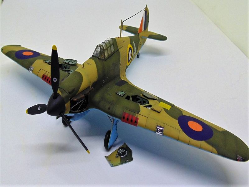
1⁄48Hawker Hurricane Trop
...
Post a Comment
INTRODUCTION FROM ITALERI
The Hawker Hurricane has been the most widely used fighter by the British Royal Air Force at the beginning of World War II. The Hurricane was powered by a Rolls-Royce Merlin 12-cylinders, liquid-cooled, with more than 1,000 HP. The eight 7.7 mm Browning machine guns, which equipped it , guaranteed a good firepower. Although it was slower and more antiquated, for aerodynamic design, than the famous "colleague" with whom it shared the operational engagement during the Battle of Britain, however, was more robust, cheaper and easier to maintain and repair. On June 1940 the first Hurricane Mk I Tropical version, characterized by the adoption of the Vokes air filter, appeared. Several Hurricanes were deployed in Malta and in North Africa.The Build
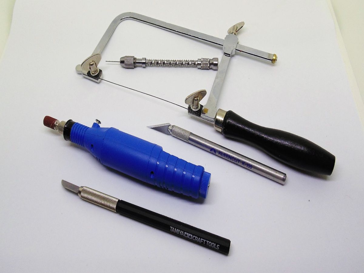
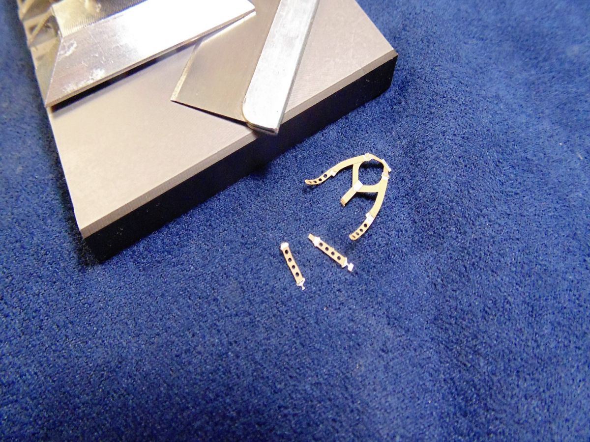
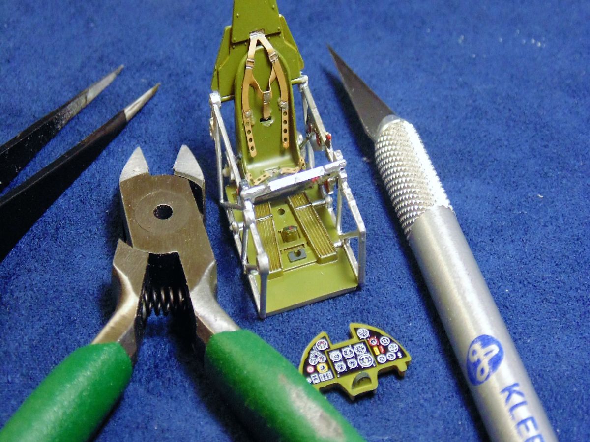
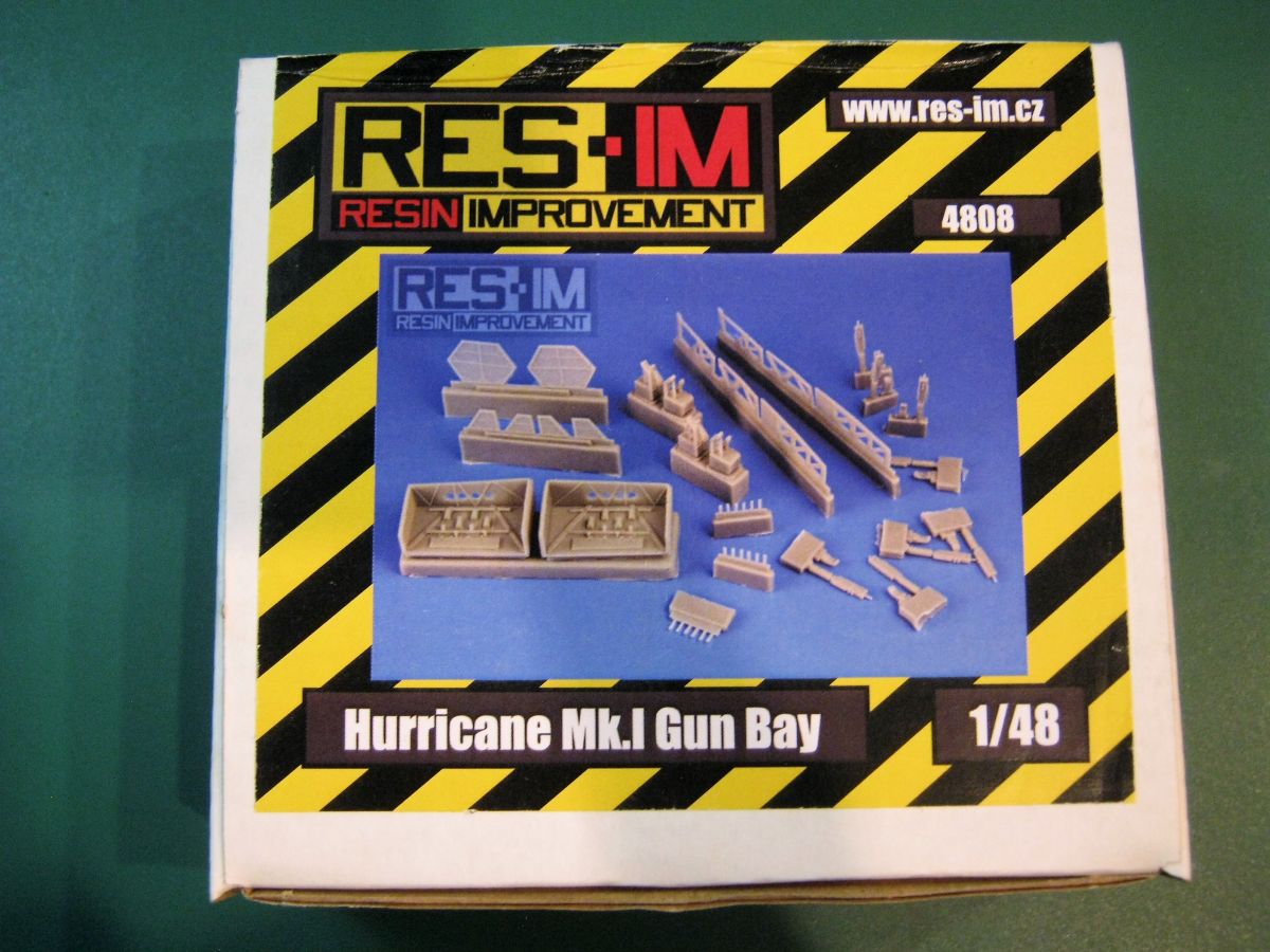
To begin this build you must have a plan of action and decent understanding of how the parts fit and in relation to how you will perform the next step(s). Naturally I'm talking about the RES-IM Mk.I gun bays. It'll be crutial to have the nessesary equipement as well.In one of my photos you'll notice the basic tools needed to perform surgery on the wings, but we'll get to that later in greater detail.
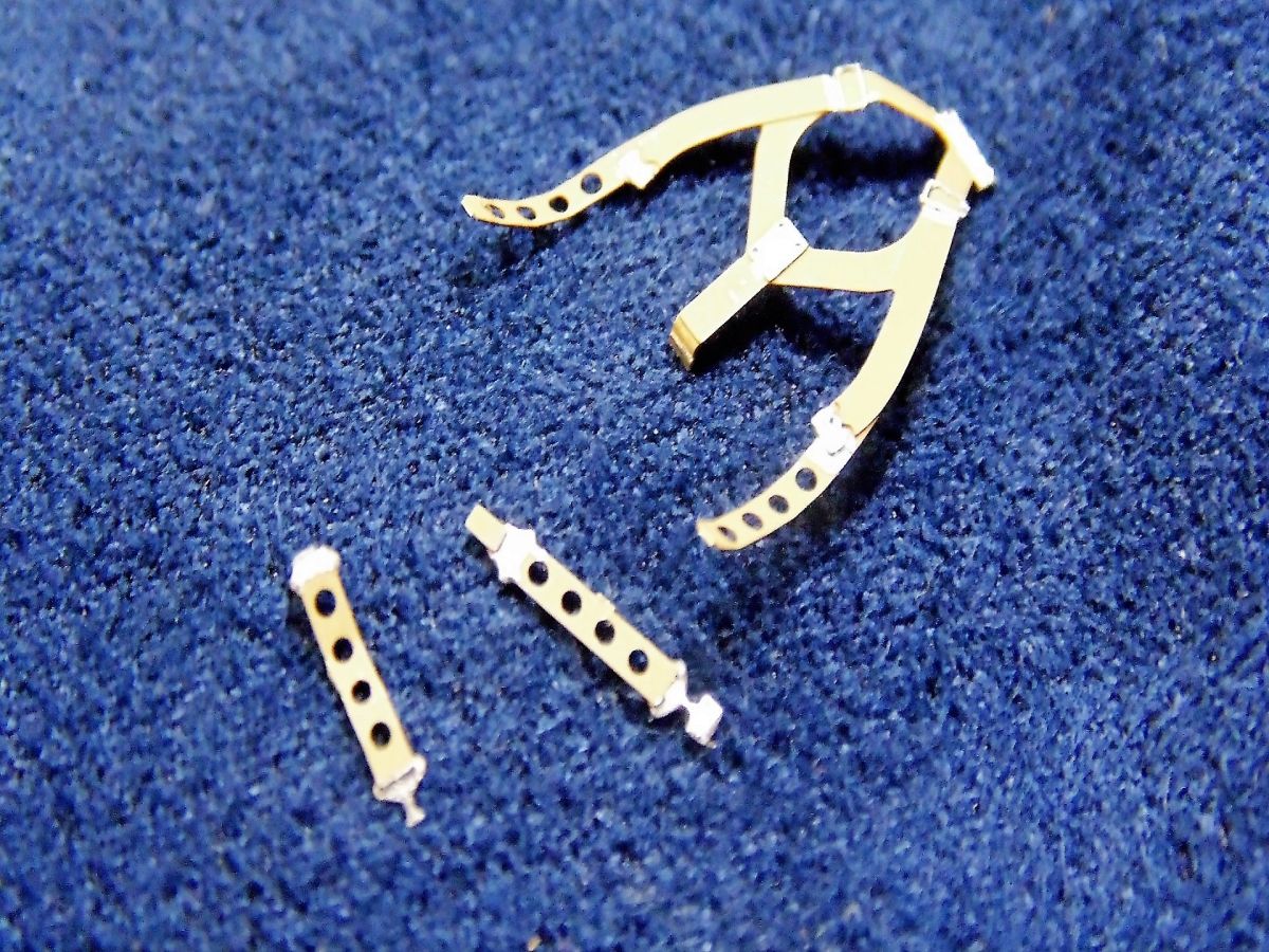
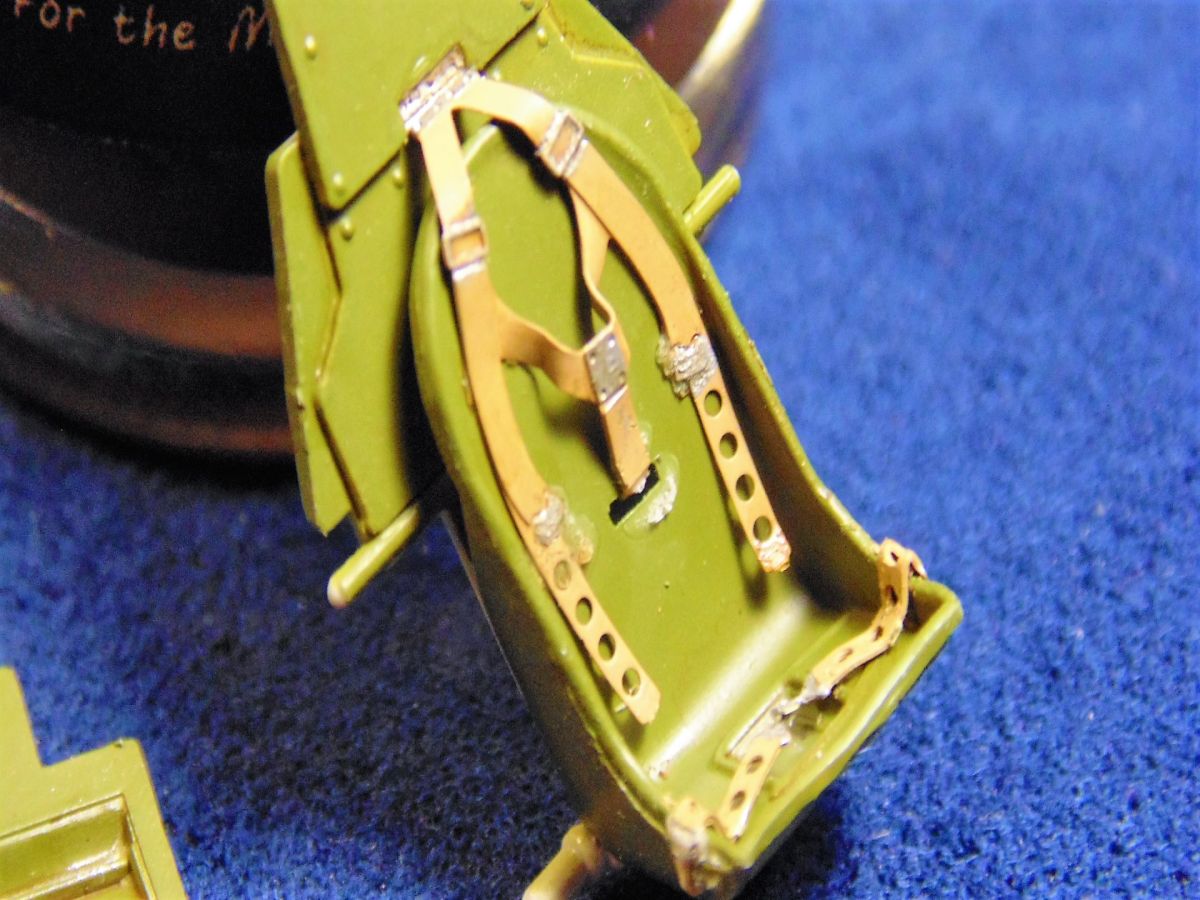
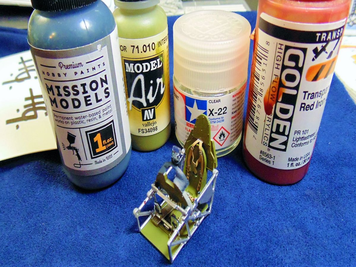
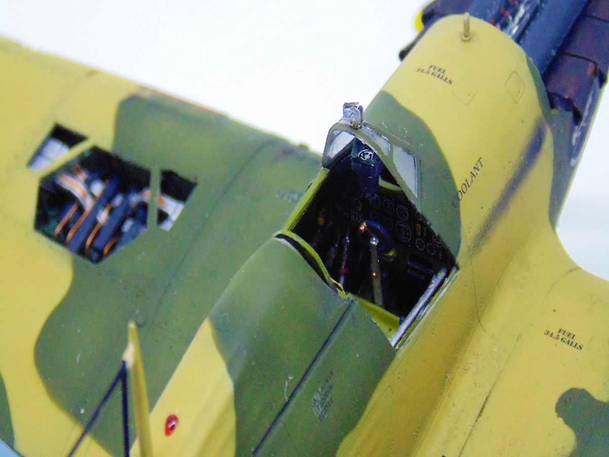
STEP ONE looks fairly simple, and while the Photo Etched parts were easy to remove from the fret and have nice detail, the main belts are considerably larger than the place they should fit into on the seat-back. The center has to be bent (as I opted for in this demonstration) or you'll have to snip a little and make them fit. This is something I hope Italeri will address by having someone build the model prior to release in order to make simple changes. The main color was interior green by Vallejo Model Air 71.101 over my favorite Mission Models Primer and Testors silver highlighted the cage detail. I resisted the urge to use a color from the numerous on-line references in favor of the Italeri suggestion, the look turned out not bad.
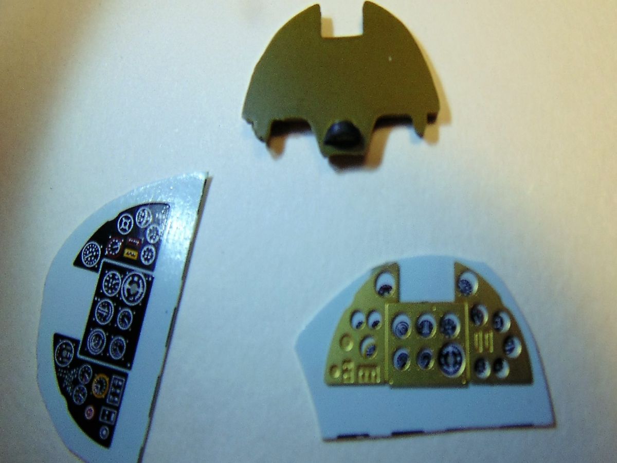
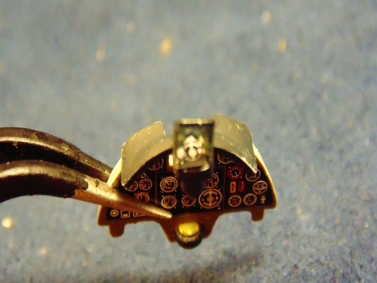
STEP TWO Has you place the support for the control cluster. Word of advice, DO NOT cement it until you've found the proper position with the dash and then with both halves of the fuselage. The parts are not very accurate to the instructions and luckily I've done enough Italeri offerings to have known this. Much patience is needed, but you'll figure it out. Next is the control cluster PE, and Cartograf decal(s). Again, some more advice for the manufacturers of both, they do not in anyway fit. I even thought about cutting the decal for the each small section of instruments, but they would not line up. You can see what I mean by the photo and it's a shame really because this is a selling point of this kit. Happily (well not really) there is another decal for use without the PE. That said, I didn't want useless material to go to waste so I scratch built an indicator for under the gun sight using some PE and a decal then a few drops of Tamiya X-22 clear. The photo doesn't do it justice, but trust me it looks really neat and accurate to the one used in real life. Enough blabbering lets move on.
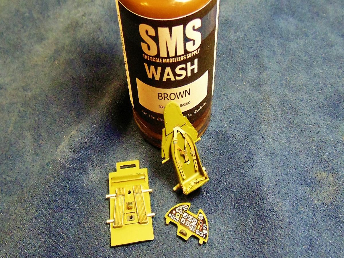
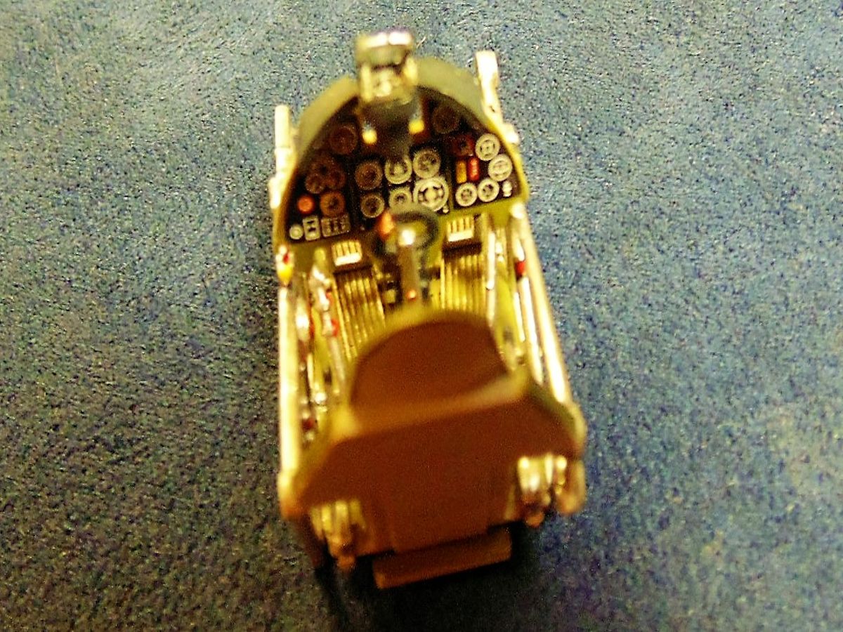
STEP THREE Has the final assembly of the cockpit. Italeri have placed a side view of how things need to look, yet once again I'll strongly suggest you test fit and test fit once more with at least one half of the fuselage (both is time consuming but much preferred). After all the detail painting was complete I used a 50/50 mix of Tamiya X-22 clear and X20A thinner prior to the weathering wash.
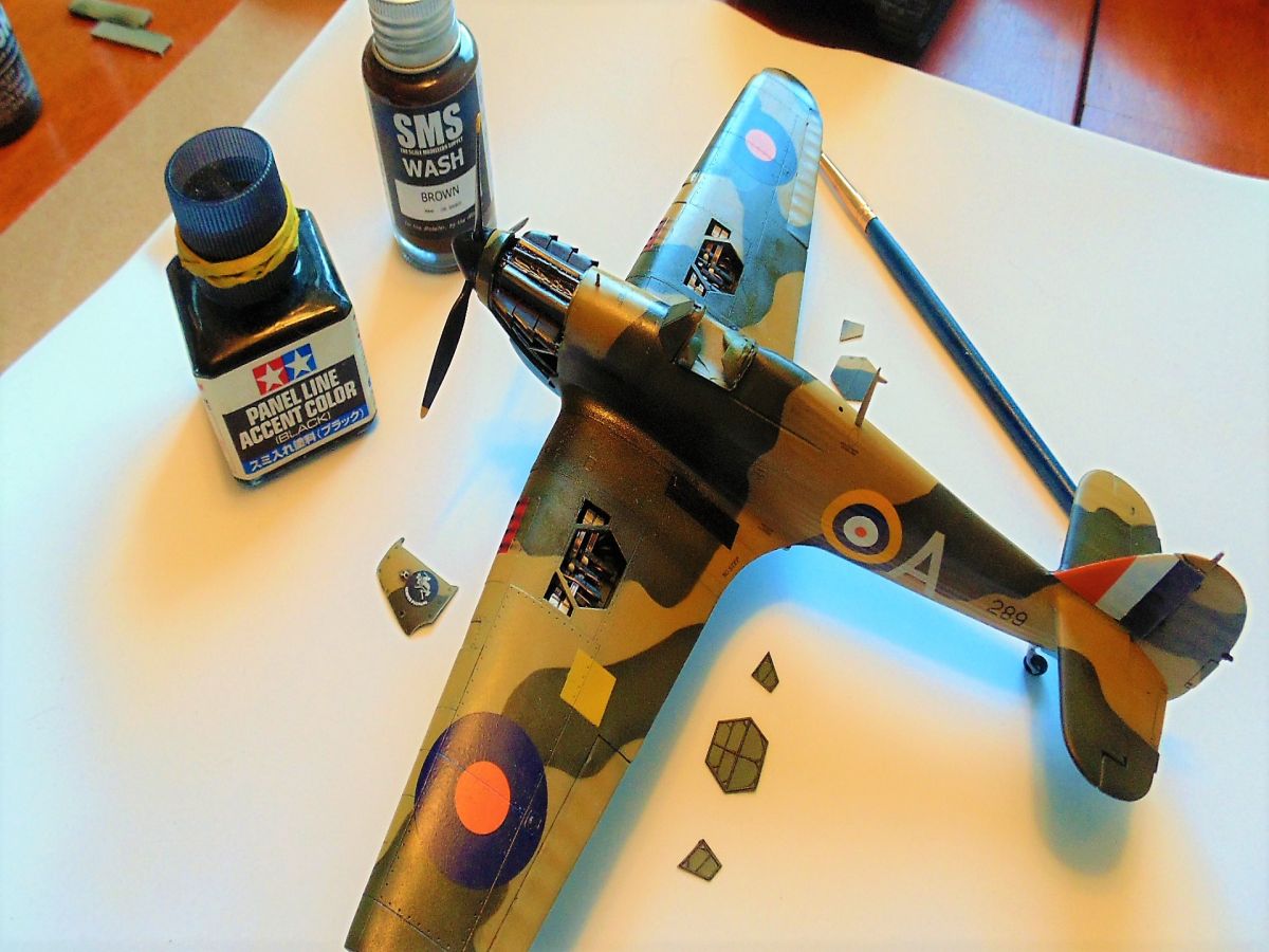
I support home based small business and recently happened upon an Austrailian company called SMS or The Scale Modellers Supply. Their BROWN oil wash is ideal for people wanting a highlighted look but not as bold as black. I'll be doing a more comprehensive article on SMS washes, pigments, fixers, and paint in the future.
Overall you'll like the detail and look of the finished cockpit once you iron out the few issues with fit and errors in some of the details. There are plenty of online photo to aid in the detail.
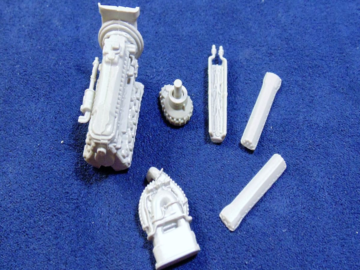
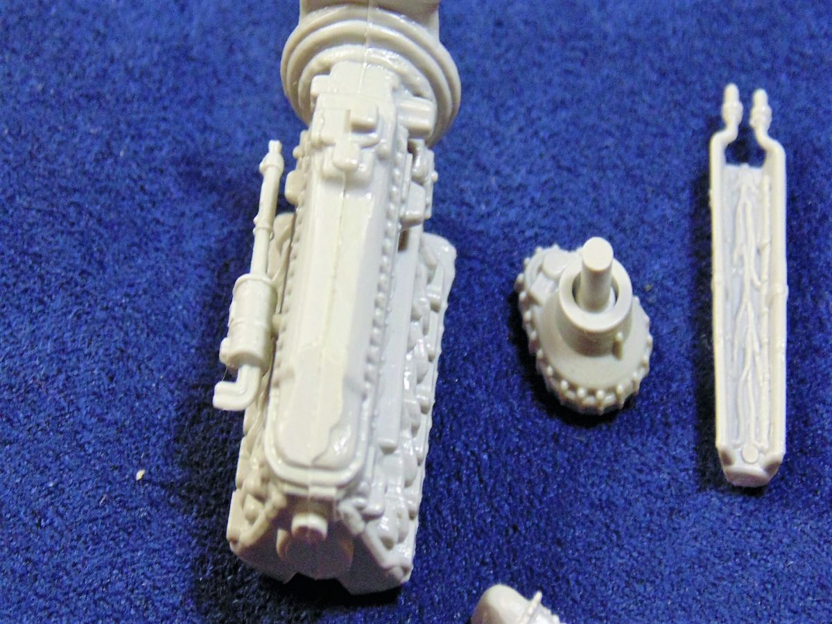
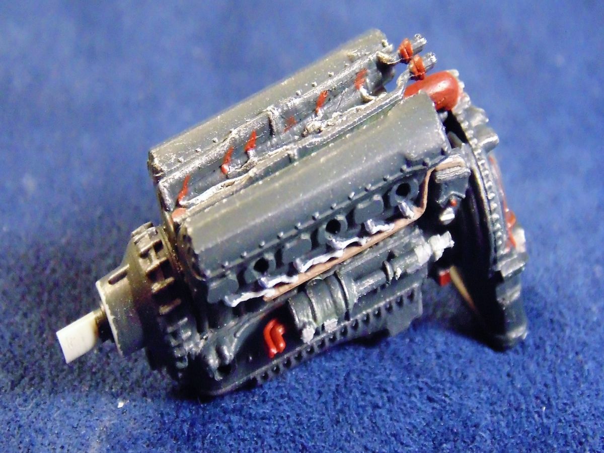
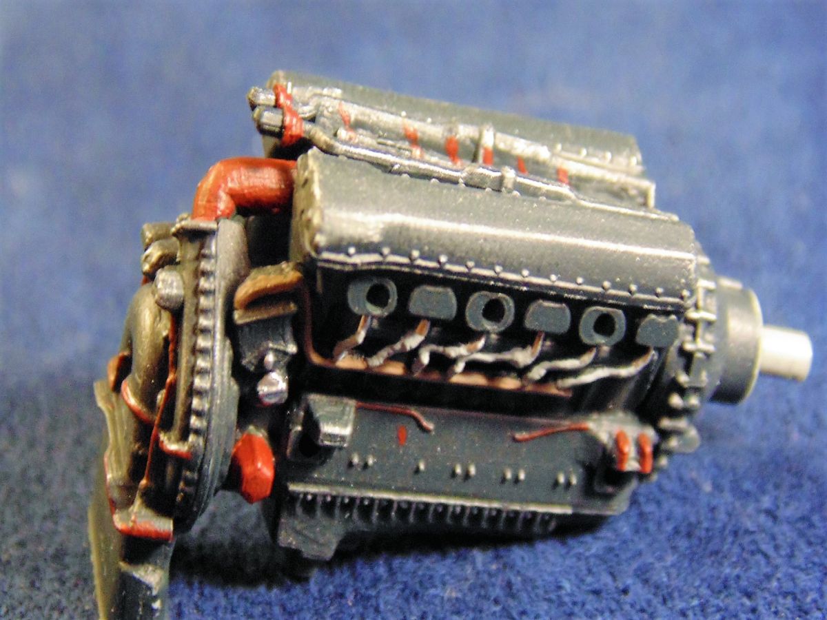
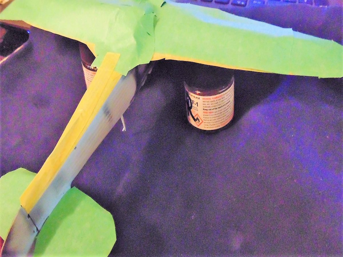
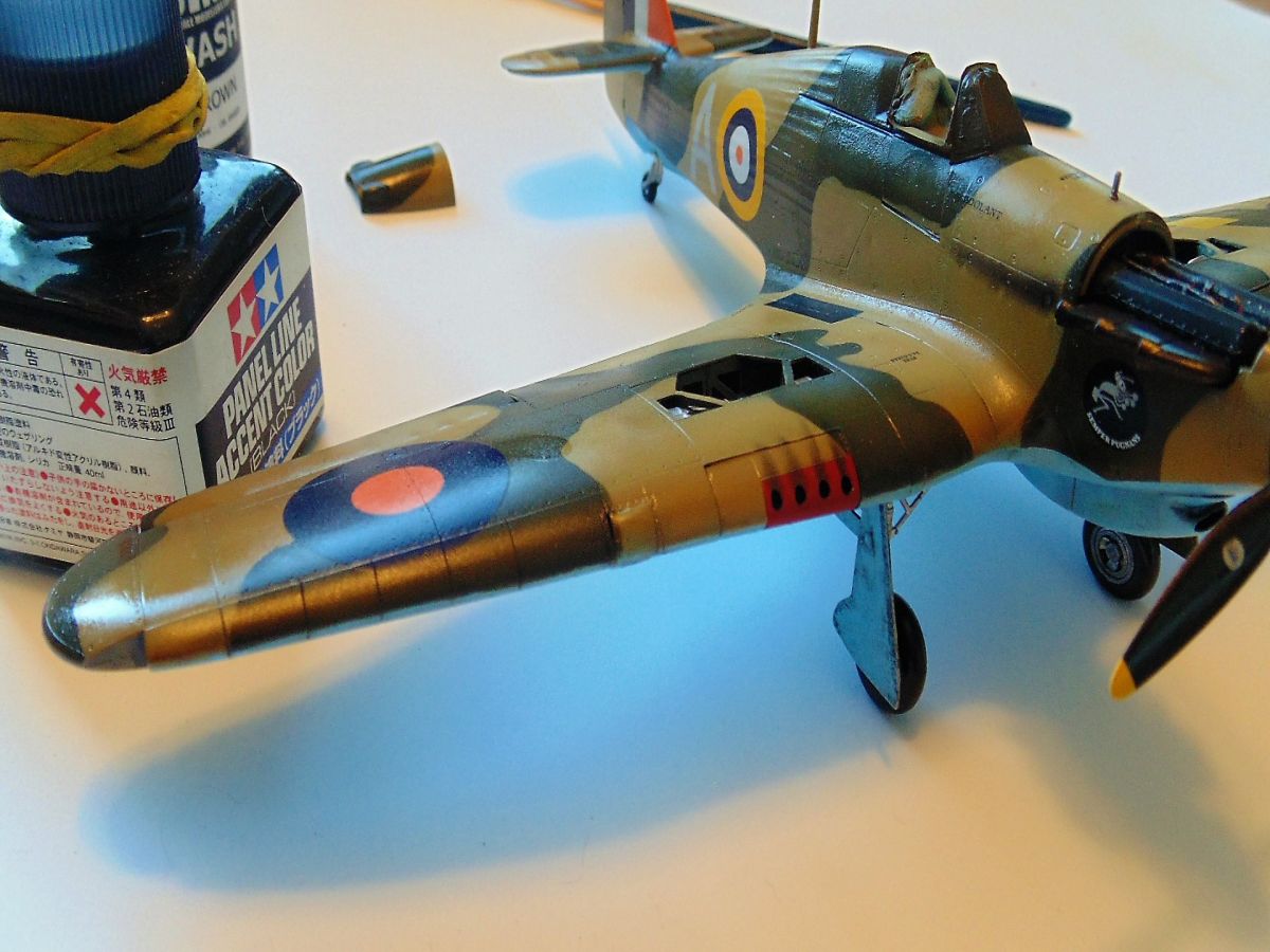
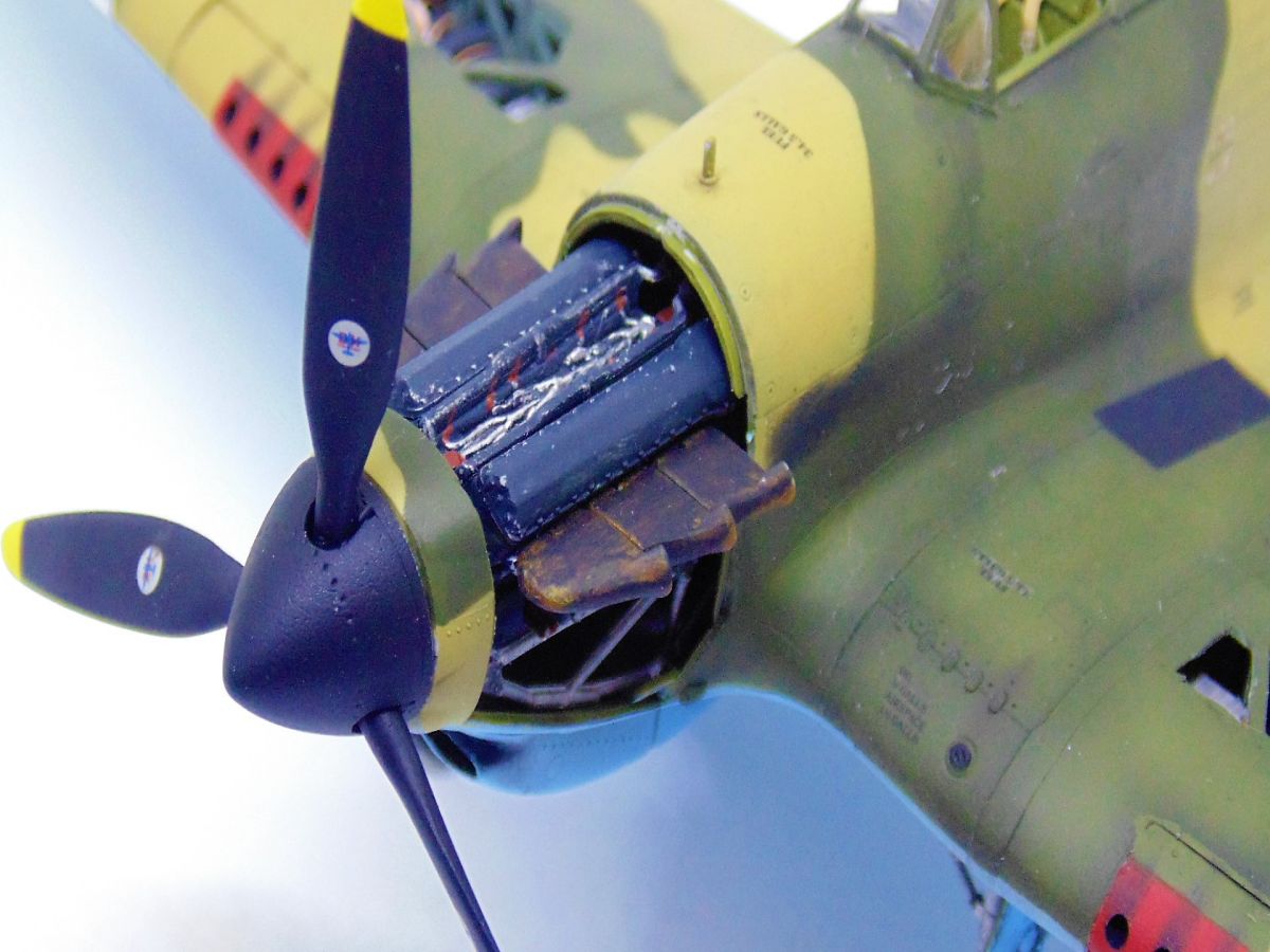
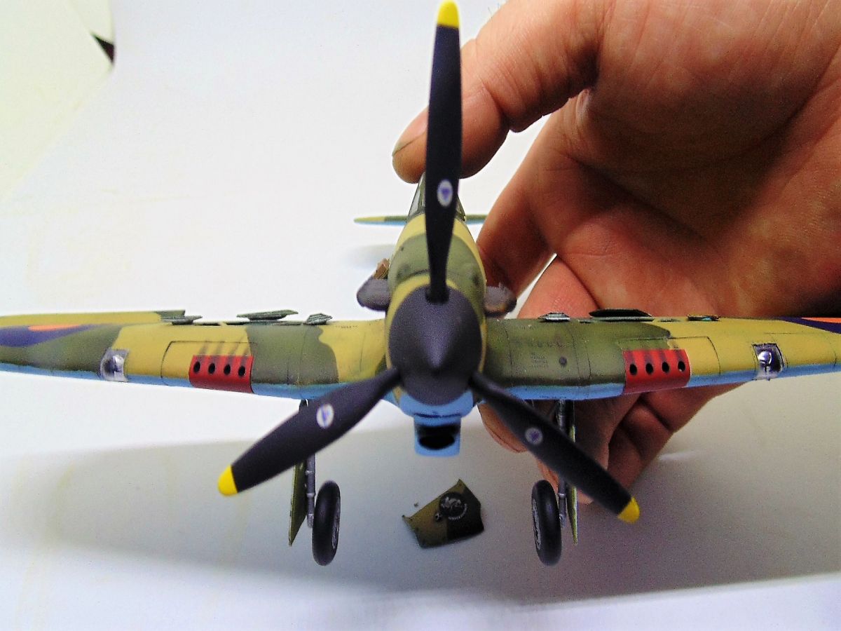
STEP FOUR Begins assembly and final construction of the engine and mounts. Again, Italeri suggest interior green and silver for the back wall and support frame. Their recommendation for flat black on the engine, however, was not something I could live with, having seen so many color photos of early Roles-Royce Merlin engines. In this case I opted for a slightly blue tint in the black and oddly enough found that Mission Model Paint Panzergrey to be perfect. It would take a black pin wash and still allow for dry brushed steel highlights. This was a personal decision as well as the red and grey detail areas. There are so many photos with different looks that you have some leeway. The pin for the spinner was a bit of work to get into place and will be an issue down the road when fixing the propellers properly. The rest went together fine, but like I said before, knowing Italeri I made sure the holes were opened up. I'd rather open a hole than sand a pin. The best part of this sub-assembly is that the detail is great and what's more, if you want to add finer looking spark plug wires and hoses along the frame... then have at it. Definitely a highlight of the build.
STEP FIVE Brings sub-assemblies E and D into the two halves of the fuselage plus the engine exhausts. Vallejo interior green was back in service once more and has a nice accurate hue over a Mission Models light grey primer.
My father-in-law was a navigator/bomber during WWII and trained in early twin engine aircraft. If anyone would have a close up and personal knowledge of this shade it was him. The only thing I found with Vallejo Model Air is that it does not like Tamiya extra thin cement. Maybe it was something I did, and trust me I'm not ruling that out, but I had to clear and surfaces before applying cement.
Before any of that, I took the time to hollow out the exhaust ports. My method is simple, use a blade or needle to form a pilot hole than your precision drill to remove most of the plastic. After that your sharp blade will cut the angles to form the look you want. Takes time, but the look is nice. Getting the proper tone for them, though, was tough. The only photos I could find were of replicas. Knowing these were new aircraft being sent to the tropics I opted to go with often used copper because of the heat dissipation and blackened it using SMS soot pigment then a slight brush with Tamiya weathering master B rust. Once more it took some time but the subtle effect looks realistic as apposed sticking out like Rudolf's Red Nose.
Since you've already addressed the alignment of the cockpit that'll be a snap, so leave it to one side and fit the engine assembly E. What I noticed is that a little play exists forward and back. As I discovered later, having this assembly as far back as you can to the cockpit will save you "some" hassle fitting the spinner and propellers close enough to the nose. I had no choice but to snip the pin on my model because the fit was way off. Regardless, the engine does snug in tight after you find that balance between where Italeri have put the position tabs verses what their instructions tell you. One important note in assembling the two halves this a bar in the middle of the port side engine exposure of the fuselage. DO NOT remove it! Wait, as I did, until you've joined both halves or otherwise the nose will be a pain to line up without having to fill and sand. It's part 21 on the sprue map.
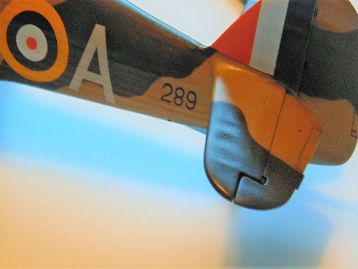
Once you're happy with how E looks place your cockpit and carefully work your way cementing to the rear of the Hurricane. The slower the better to avoid filler and the fit will be fine with some care and tape. Italeri molded the seam at the base of the rudder slightly offset. Bend the plastic a little and you'll get a snug fit. I only had to use a pin drop of putty on the entire body section in front of the cockpit. My least favorite thing about this hobby losing detail because of putty and sanding.
Before I move on, a quick note on Rivets. Italeri have placed a nice amount of detail in the removal bolts inset in the model. I could have used my rivet wheel to add more detail, but thought it would look goofy to have all those marks at the front then you get to the canvas back and see nothing. This will be yours to decide.
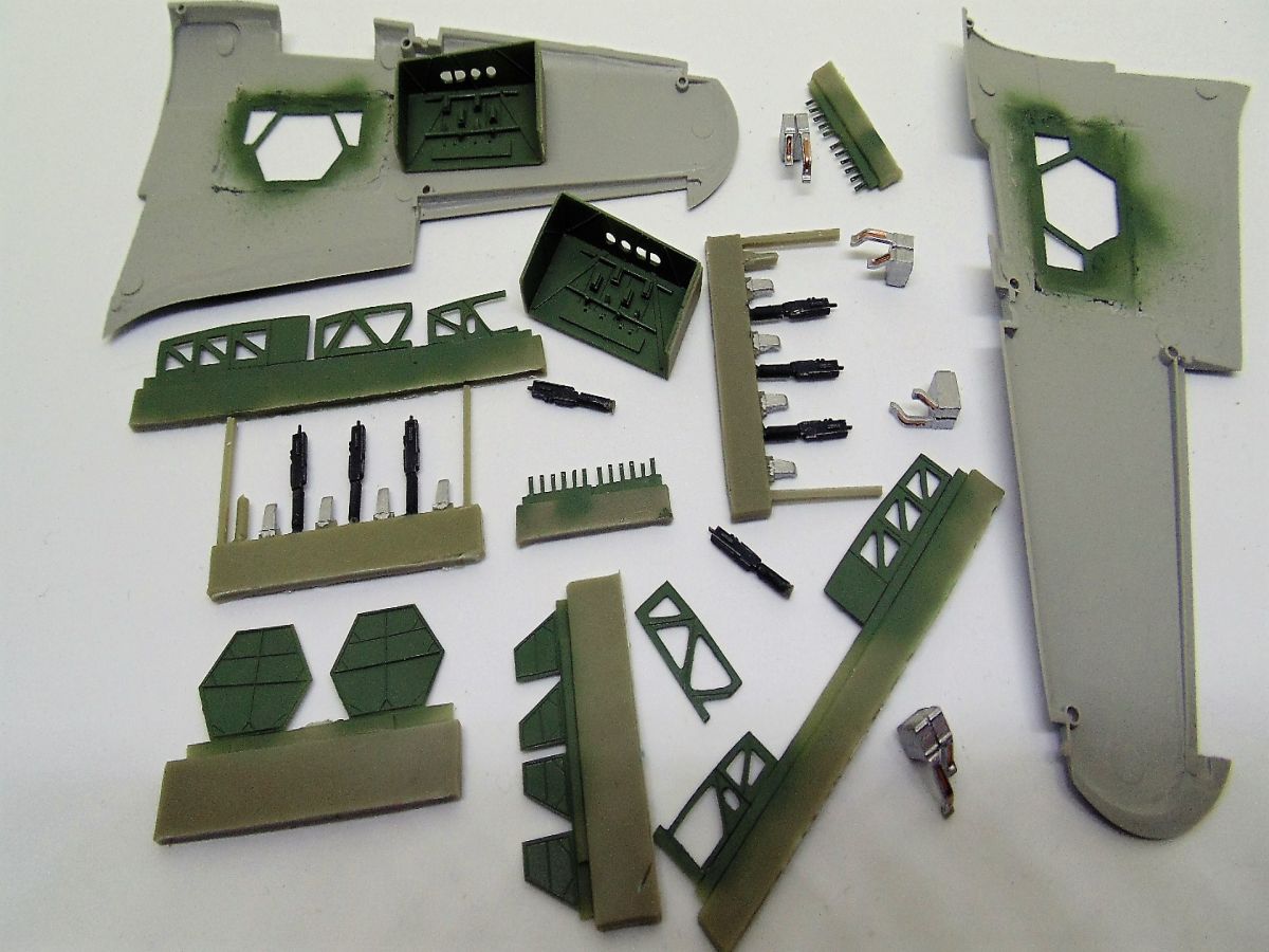
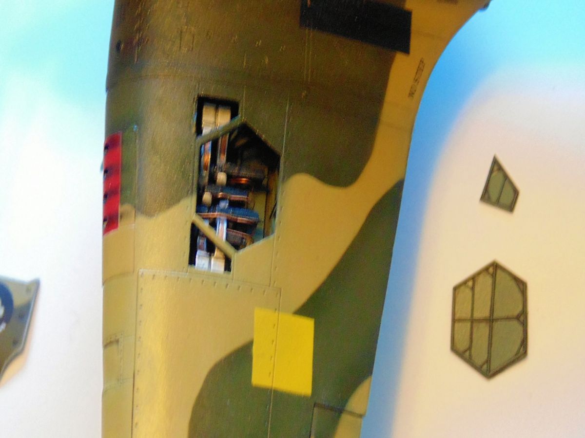
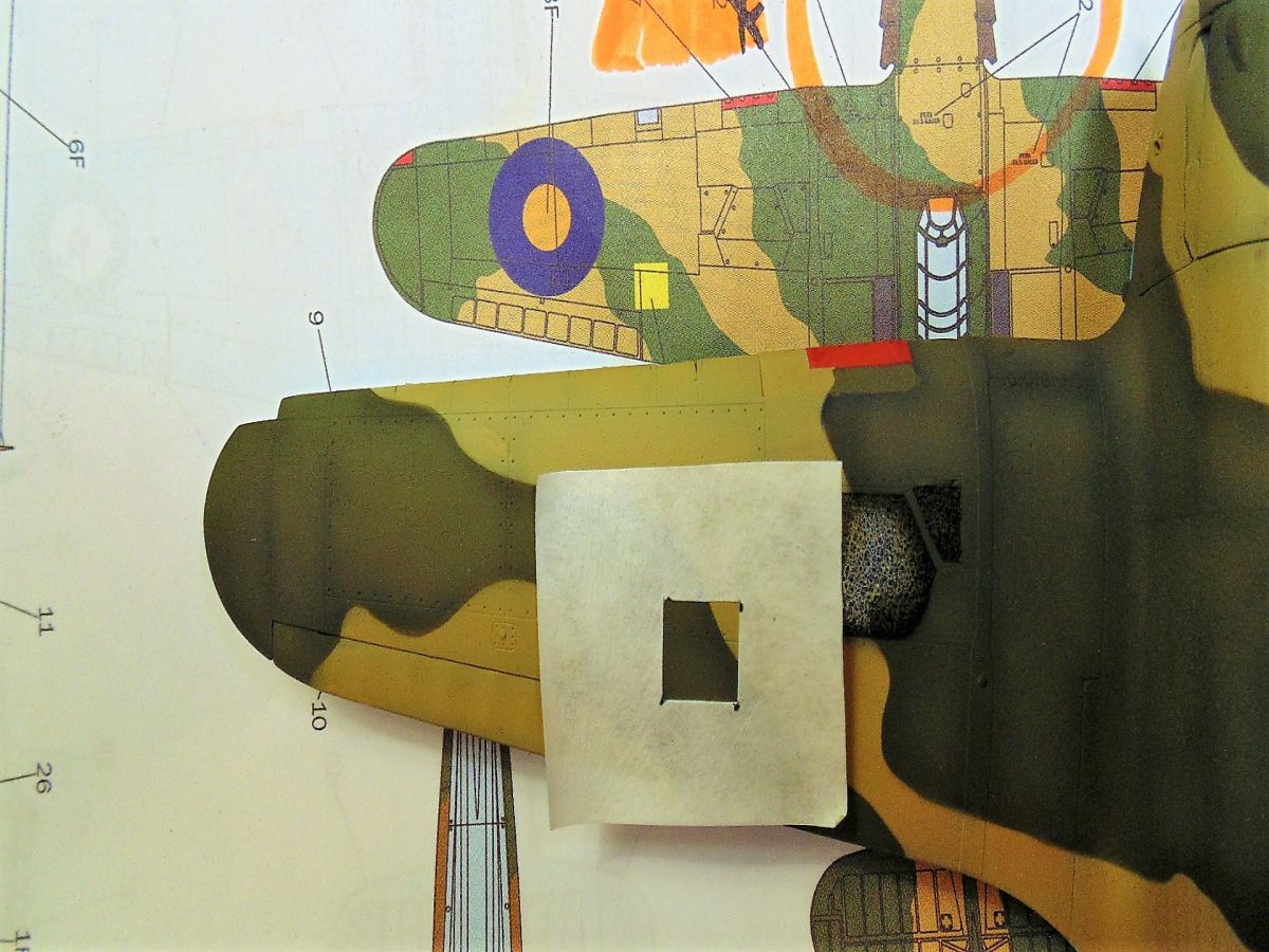
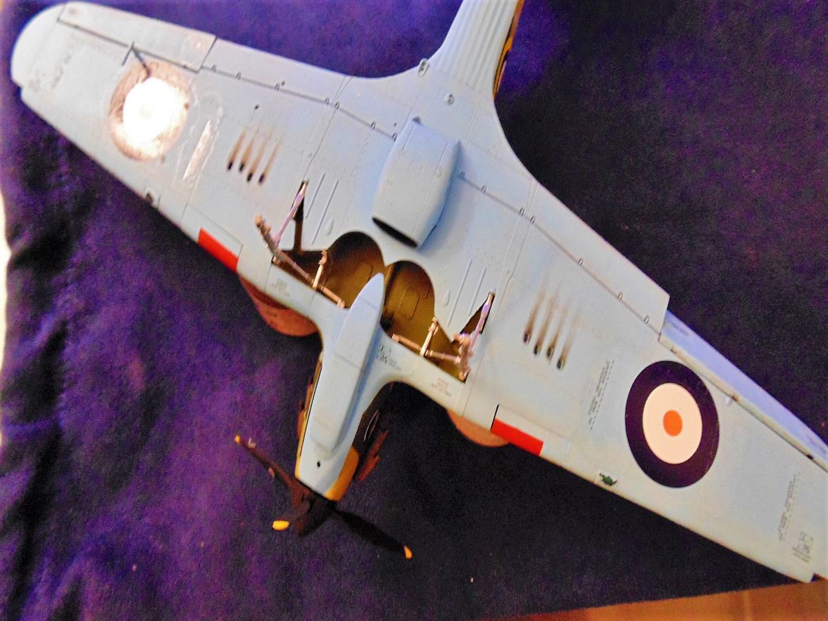
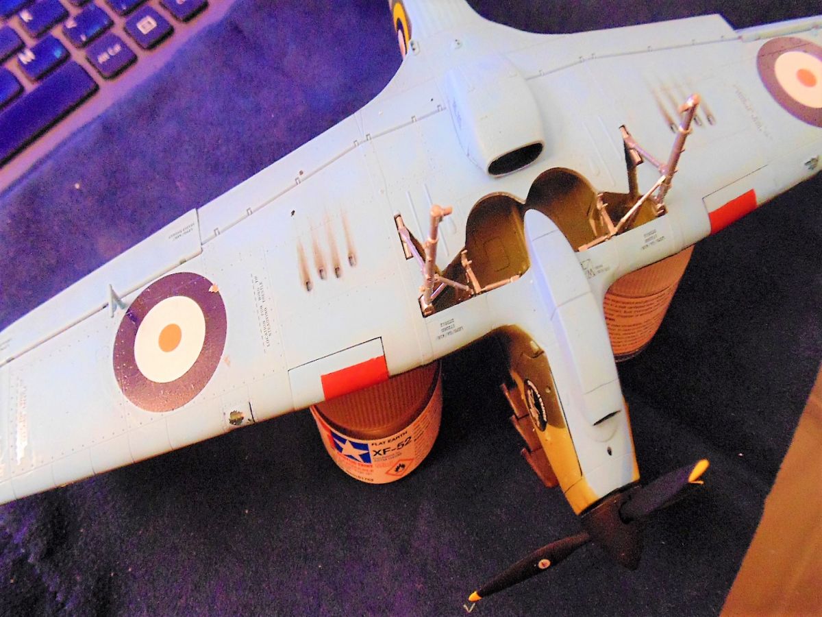
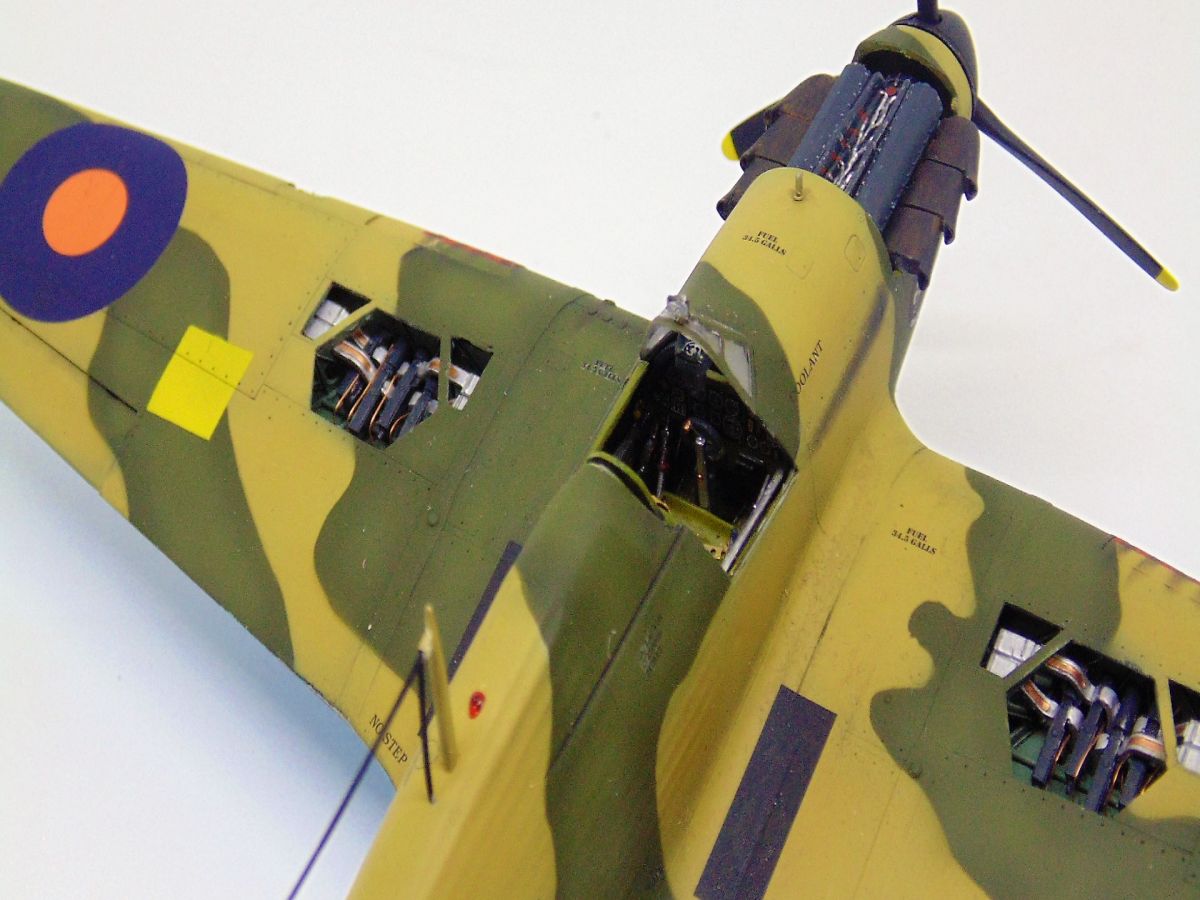
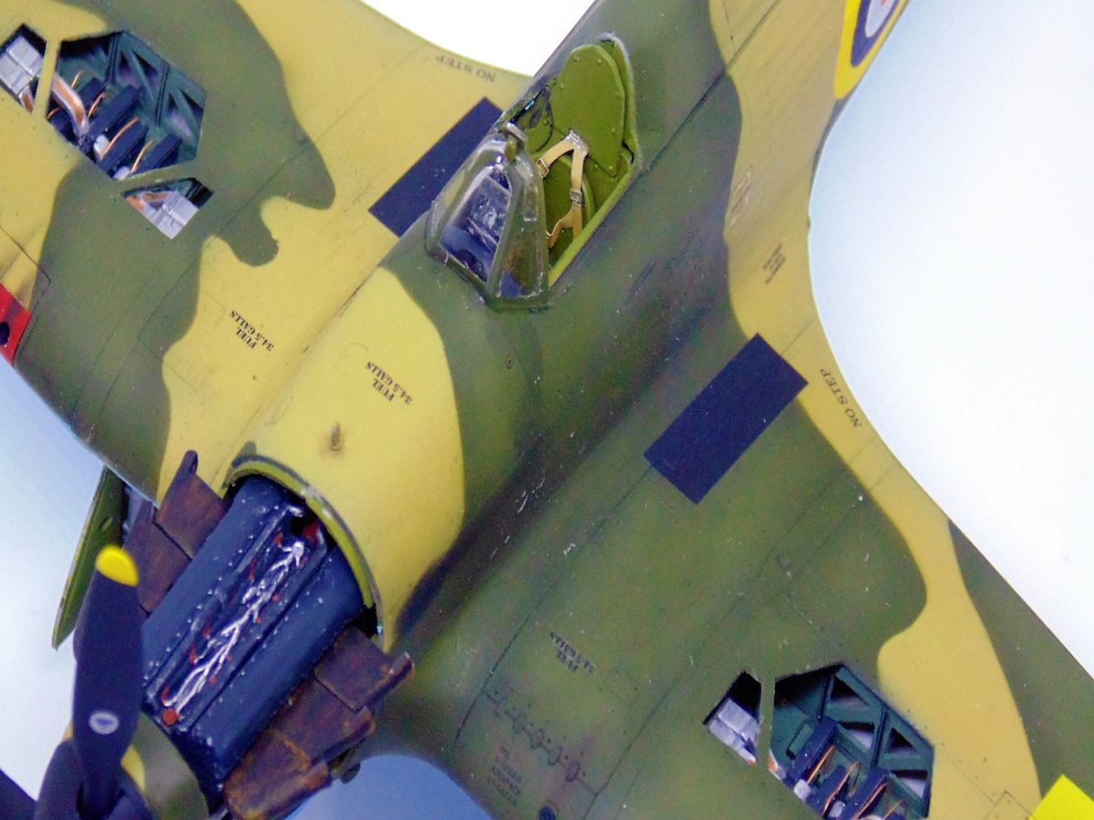
STEP SIX Is the most labor and mentally intensive section of this model. This is where the RES-IM gun bays get placed. These are not for the average modeler and require skill with resin, rotary grinding tools, knowledge of proper ventilation and safety, an extremely steady hand, and using wet sandpaper or sanders. A very precise fine pair of tweezers is a must and be prepared to walk away and return when your calm. Let me repeat, I only point these things out to help RES-IM make a better product and a happier user experience. So here we go with that assistance from a modelers perspective. The instructions are a challenge because they are missing so much detail in how they are poorly printed. Washed out images would have made things easier if they were more crisp. RES-IM followed the Italeri wing lines perfectly to place the ammo and gun covers. I decided it would be better to drill, saw, cut and fine detail these openings when the plastic was thicker, for worry of breaking the thin fragile tops of the frames in the gun compartment. You chose which you're more comfortable with. Grind before or after the openings on the kit need to be removed. While the cut out piece of paper they ask to use as a placement template is fine, they don't tell you how much plastic must be removed or give any tips on how to do this. Which brings us to the main challenges you'll find with the bays. They're the fit between the upper and lower wing halves and how to thread the ammo canisters in the framework gaps and then placing the guns.
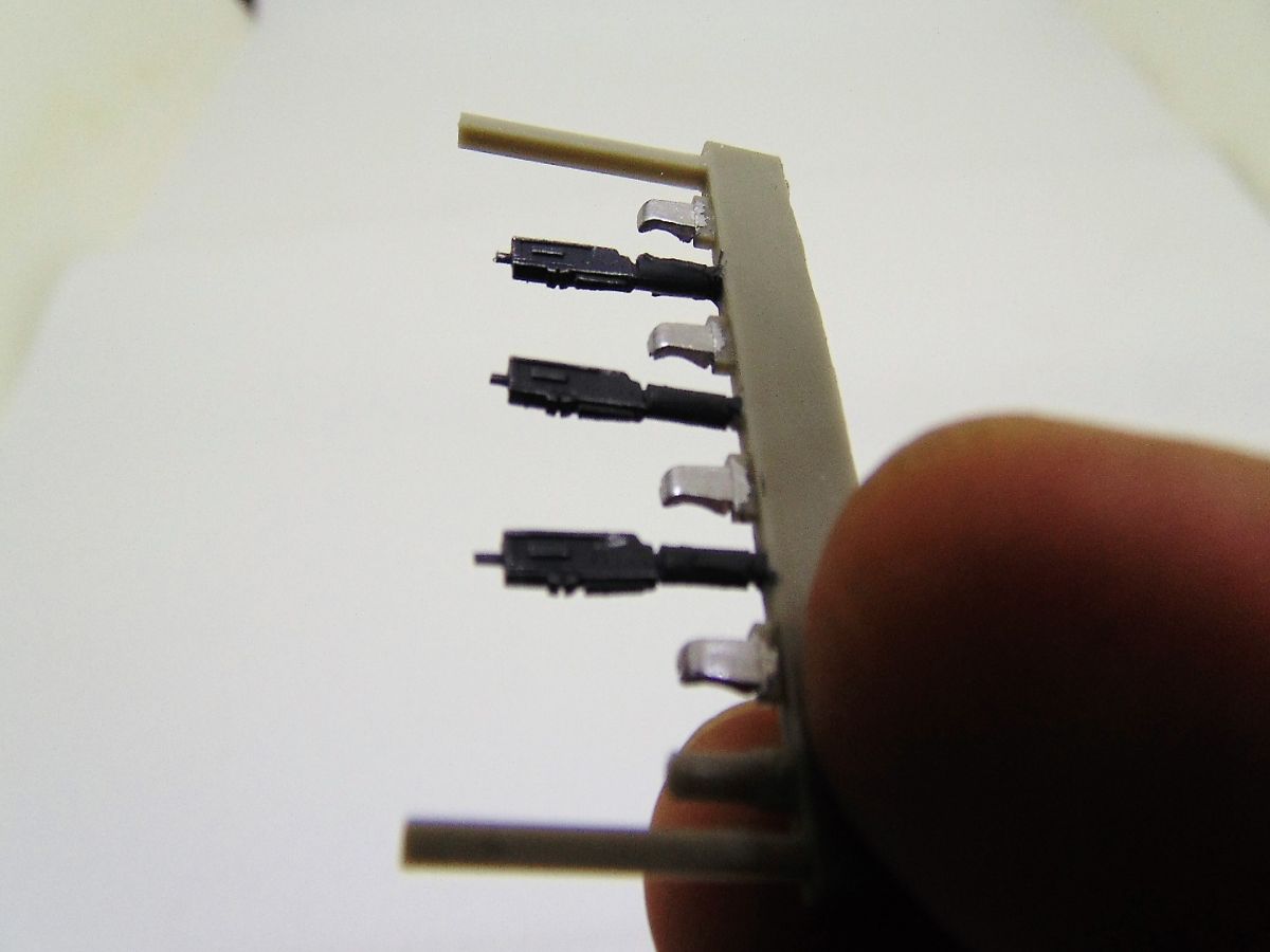
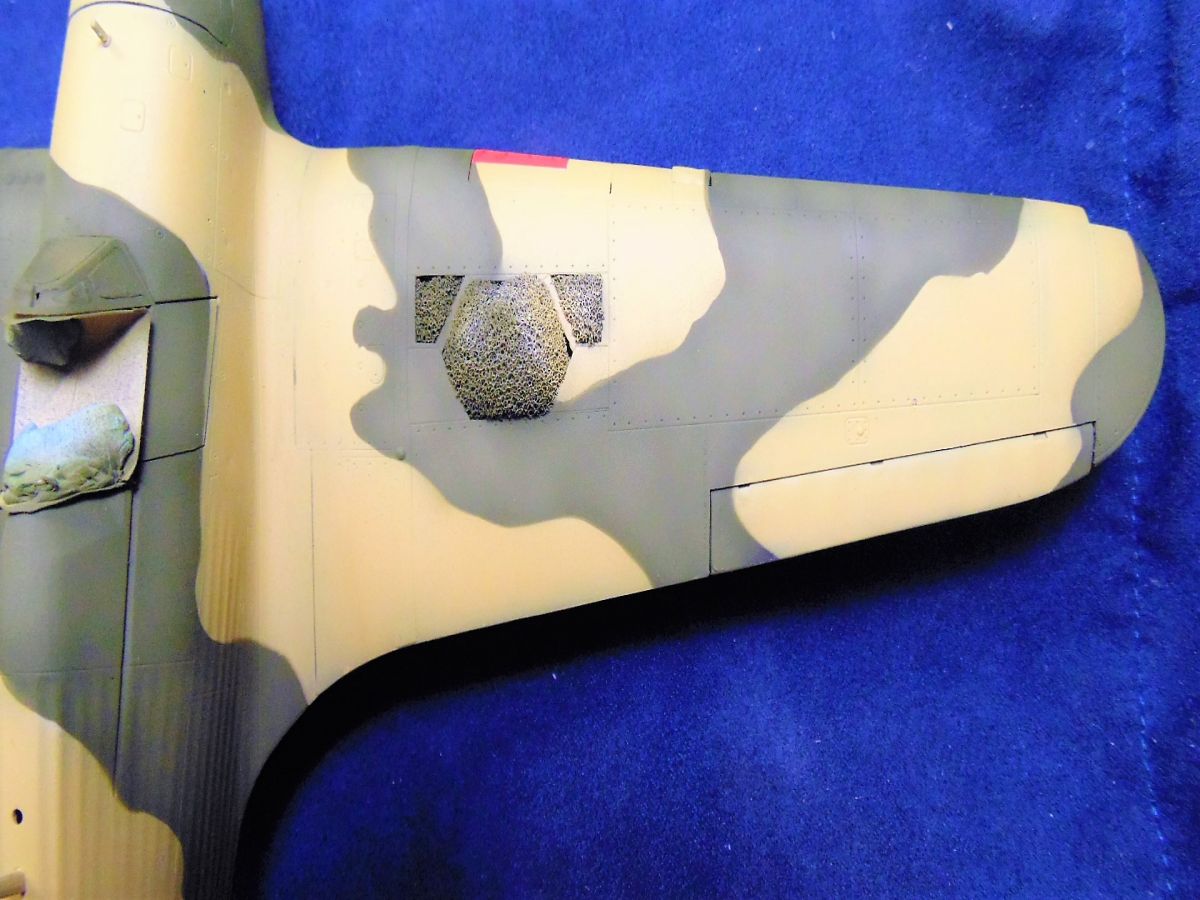
I achieved the plastic thickness by holding it up to a light. When I could see a faint translucent look it was time to try a test fit. The underside of the resin floors must be as thin as possible, again hold them up to a light to make sure you do not grind or sand all the way through. Next the bottom of the wing halves has to be ground down as well. Even when this is all cleaned up the top rim of the bays must be sanded down. Here you'll find a thinner line to go by, but again it would have been nice to know before hand. After the dust had cleared I still found a little pressure was needed on the wing halves when they were ready to be fit, but it wasn't that bad. Next came the clean up, priming, and test fitting of the tiny parts. The bay framework pieces are excellent in detail and easy to see where each is placed. The ammo canisters and delivery tracks are ok, but many photos clearly show that the magazine belts are exposed along their tracks. Some added detail will help with the look in the future. I recommend to install the framework first then hold the ammo canisters upside down and spin-fish them threw the frame gap and into place. DO NOT CA glue them yet. Find the right place for the Browning guns and glue those, then gently move the ammo canisters to match up and then finally install the exit shoots. All I can say is that this worked for me after countless attempts at following RES-IM directions. One of the happy benefits from all that trial and error was going back online to see what I was doing wrong. The copper wire/tubes you see in my photos was one of the things present in the actual bay and missing from the the resin kit. I sincerely hope this helps because once you're done... man they look cool.
The remainder of this step was straight forward and welcomed. The usual things such as DO NOT clean any flash until you've assembled the parts, plus the wheel bay needs a little persuasion to be in the correct spot.
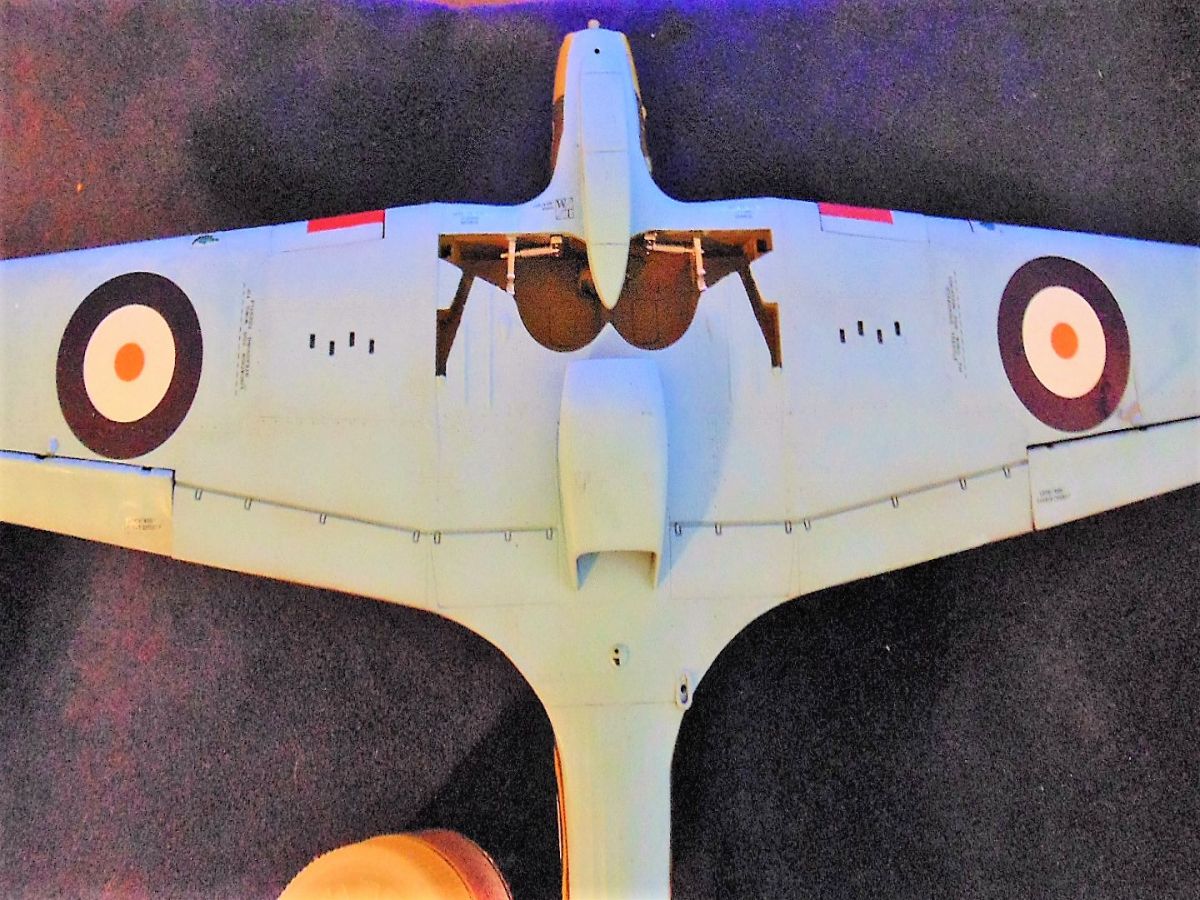
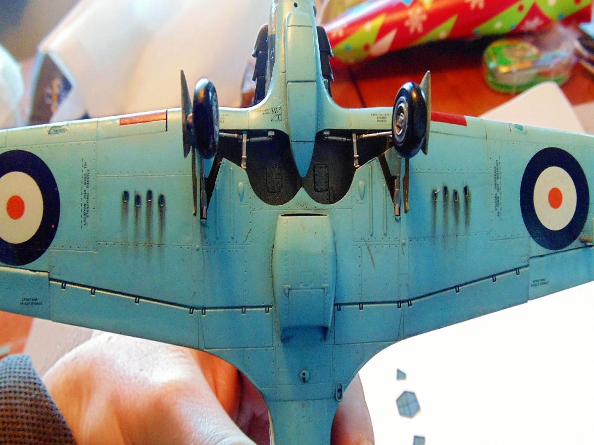
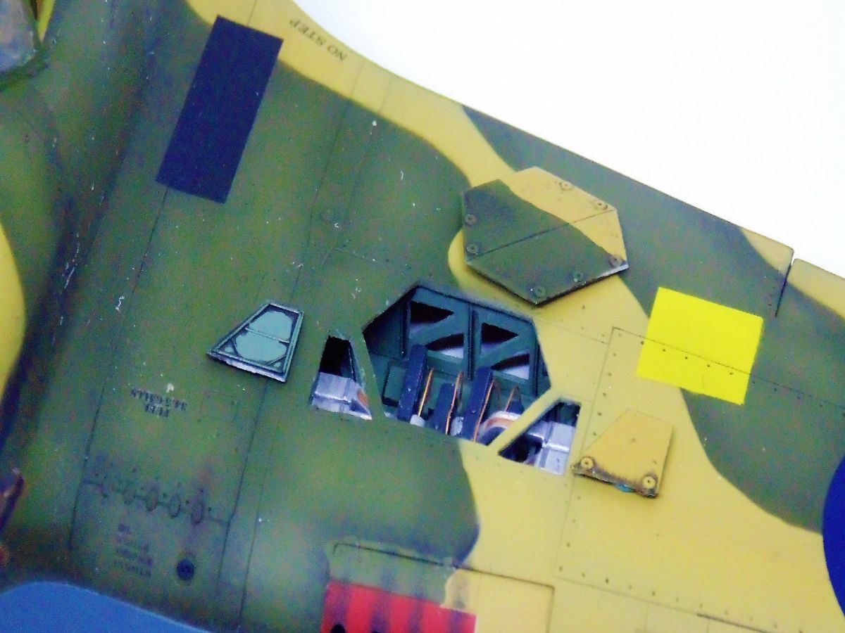
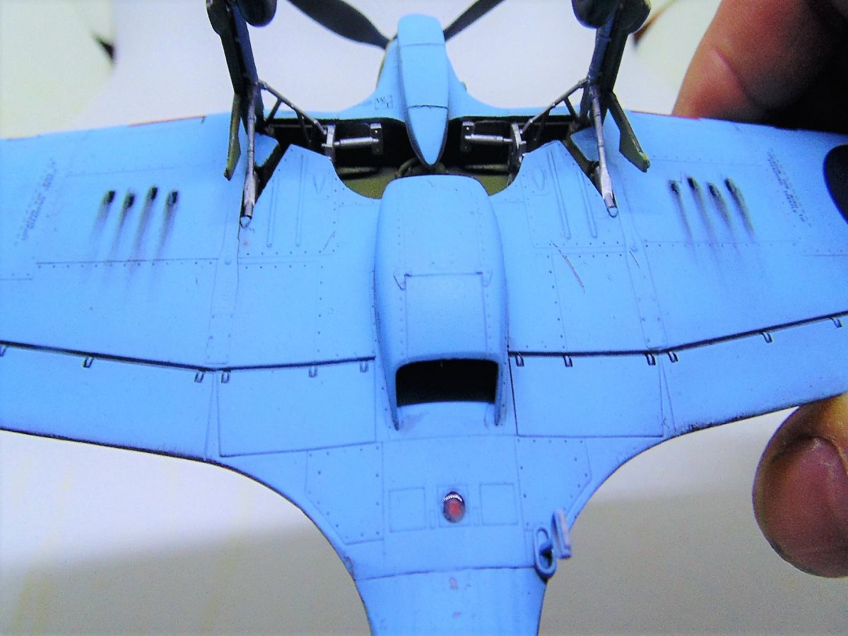
STEP SEVEN Was a head-scratcher as my photos show. The front ventral end of the lower wing was never made to fit this kit, leading me to feel it was for the regular Mk.I Hurricane. There is another example to support this later, but after 6 or 7mm were removed some putty filled the gap then the rest of that area could be sanded. You'll need rounded sanding sticks and a putty which will re-scribe. A nice thing that Italeri did for the clear plastic navigation light parts was preformed an accurate hole that looks amazingly like the real housing, including trim. I used GOLDEN High Flow colors for these lights because they are incredibly vivid for such things then set both aside to be added in the final assembly. Cartograf supply red decals for the gun ports but they look far to brilliant so I airbrushed this area for a much more realistic look. The landing lights were also well detailed including the three spoke pinwheel design found on early Hurricane and Spitfire models. Once painted in silver and flat black they were cemented into place and the surrounding clear plastic shield was covered with Vallejo Liquid Mask.
STEP EIGHT Has the addition of the Vokes Air Filter, characteristic of the Trop or Tropical version, then the coolant radiator, tail wheel, aft belly fuselage cover and a small lens for the underside red navigation beacon. For this beacon I painted the center red, the surround black, then added the clear part and covered it with Masking Fluid. The cooling system was well detailed and needed minimal sanding as did the textured fabric underside of the fuselage. The Air Filter, however, is ether too big or that miss-matched lower wing section is flawed at the wheel wells. Regardless, the positioning pin (there is only one and not two) had to be removed and measurements made from drawings needed to be taken to place it properly. This means you have to move it aft slightly to have the intake nozzle at a 90 degree angle when at level flight. It then needed a fair amount of sanding and the panel lines re-scribed. The tail wheel is weighted and the support is in two pieces. This is great because you can turn it to be flat in final assembly. After everything was done I stuffed both intakes with foam to protect the flat black paint in preparation for painting.
STEP NINE Was a simple matter of adding some undercarriage detail, yet I'd advise doing your best to dry-fit the rest of the landing gear to help with their alignment. More foam was then used along with some Blu-Tac to fill the remaining gaps. The entire area was painted in interior green with silver for the mechanical workings.
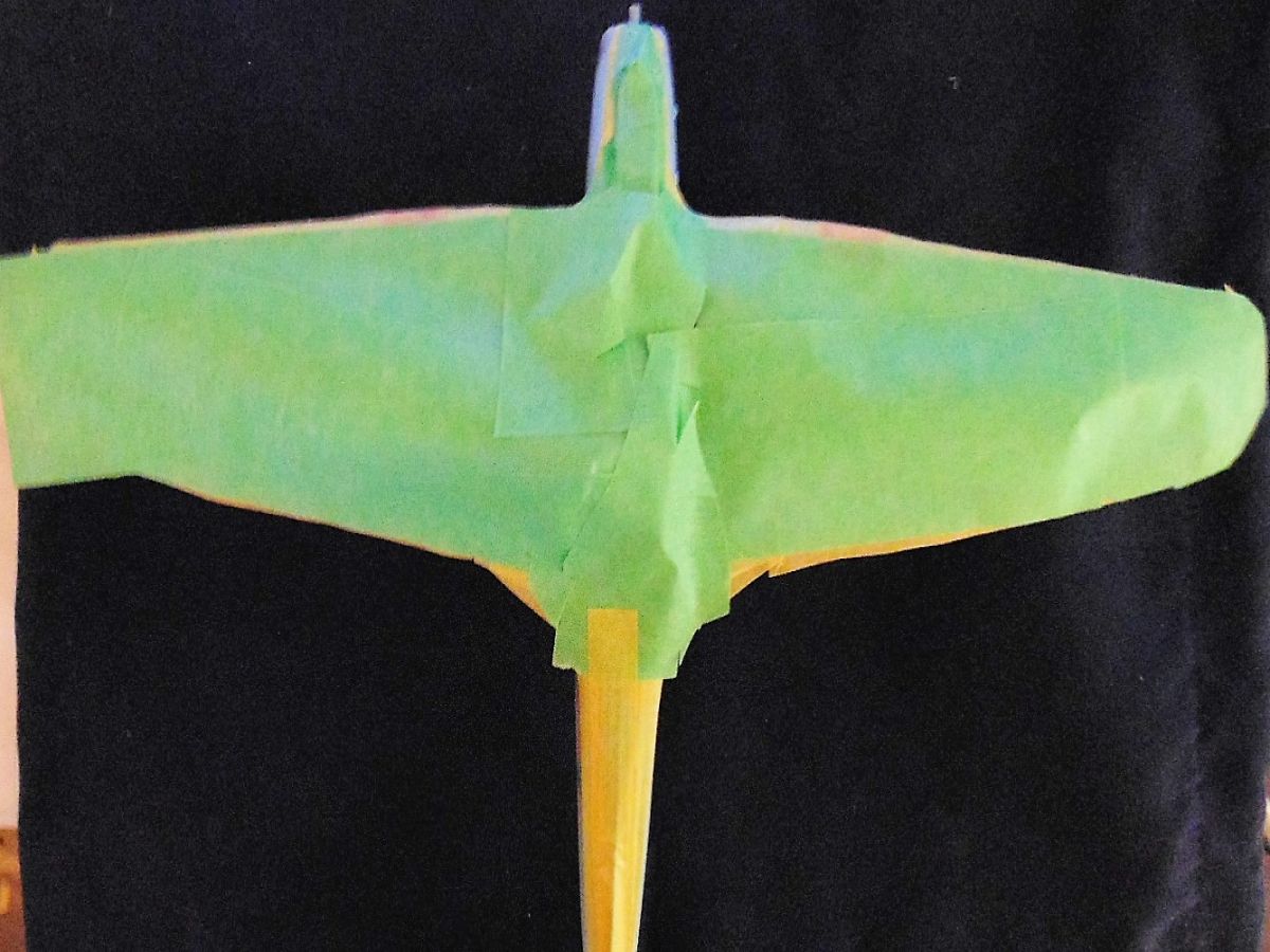
PRE-SHADE, MASKING, PAINTING, AND... Now that all the major assembly was finished I could bring out the Mission Models Primer. I had already jumped ahead in the instructions and added the rear wing parts, pitot tube, antenna stand, wind screen, and pilot escape panel. Please note that the antenna needs a lot of sanding to make it look authentic and masking tape and fluid were used for the windscreen and canopy. More foam was carefully inserted to protect the gun bays and more Blu-Tac and tape covered the cockpit and engine area after the cowls were temporarily tacked in place.
All buttoned up and primed I could see exactly how much filler to use on the wings, belly, and cover where the fuel tank sits. With those places fixed up I re-scribed a few lines and began pre-shading panel lines. I like Tamiya XF-1 for this because it's very forgiving to quickly sands off should a blunder occur. Next I used Vallejo Sky Blue for the underbelly as called for by Italeri. The look was quite bright, yet I knew the post shade would lighten it up a bit and from lots of reading remembered these planes were new and didn't have much time to fade. I masked this off after being satisfied and moved to the top.
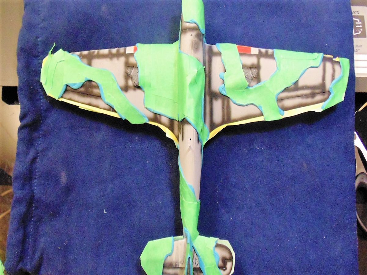
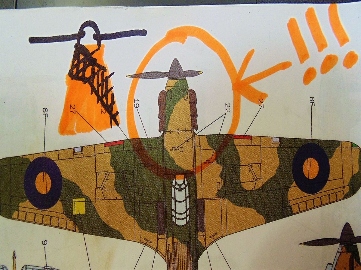
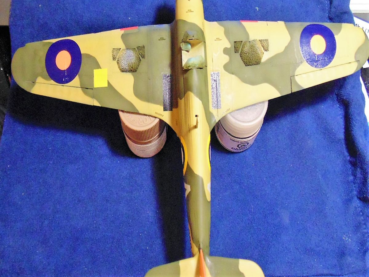
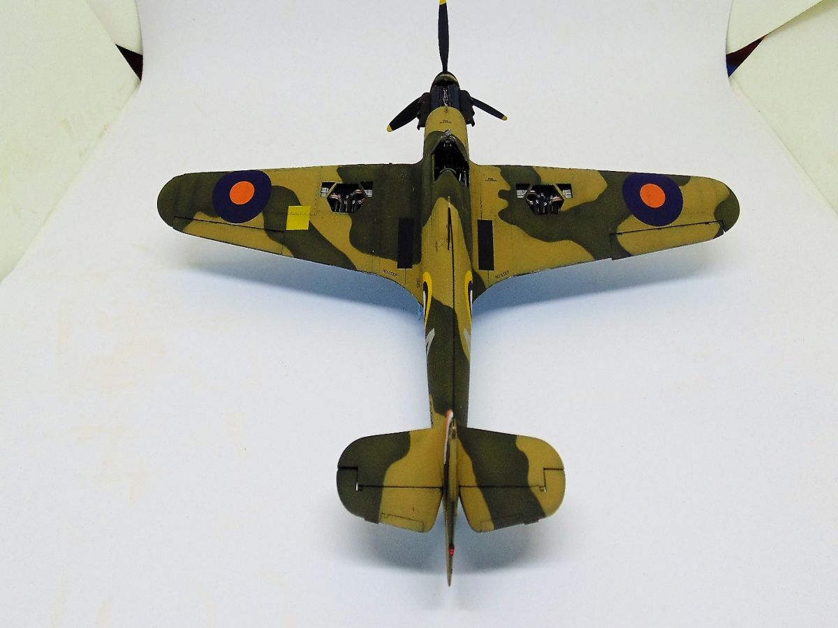
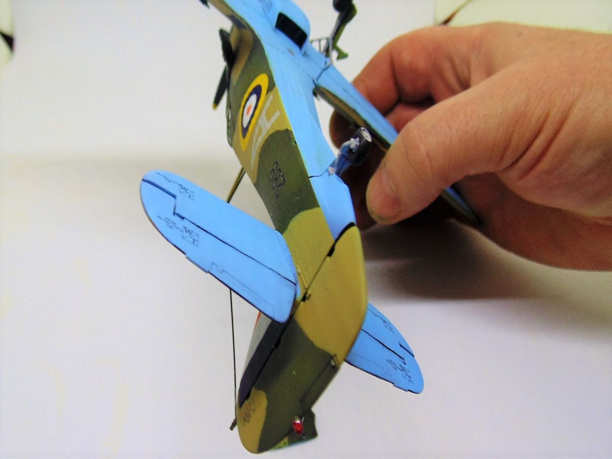
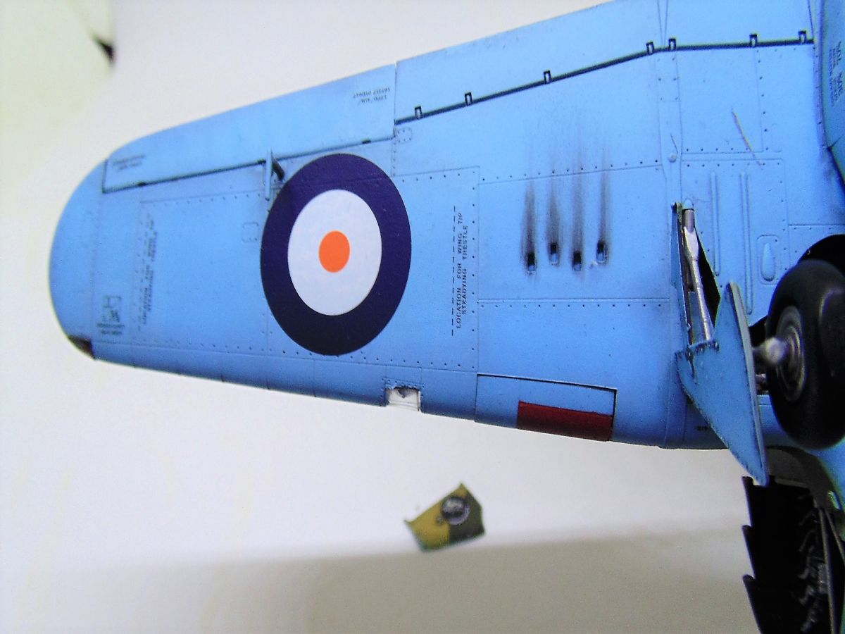
The Tropical version of Capt. John Frost's Hurricane called for the same colors that the Italeri brand of paint suggest. Yet what they say in the instructions for non Italeri paint requires a further look. That said, I used Mission Models Paint olive drab and middle-stone. Following the camouflage pattern from the instructions I again used Blu-Tac and regular painters tape. The Blu-Tac can be easily made into thin rolls by taking your index and middle finger and spreading them apart as you roll. This is fast and uses less product, meaning less to clean up. For this paint job I laid down the middle-stone color then the olive drab. Once they had fully cured overnight I added one drop of white for ten drops of paint then did my Post-Shading. Soot and oil spills were then added and a square mask was made to airbrush the yellow square on the port wing. Tru-Color Paint offer an excellent thin sheet which is ideal for cutting into shapes such as the one for my square. Again, the Cartograf decal was far to bright and toy-like.
DECALS Once I was happy with the look of the paint it was time to add the water-slide transfers. Mission Model Paint is excellent because you don't need to clear coat and very little raised or recessed detail (if any) is lost. That said, these were the worst Cartograf decals I've ever used. Very strange since many have been used before and after with incredible results. After ten coats Micro-Sol the roundels still had some slight bubbles even after using a spare .02 airbrush needle. It is what it is, and will be left that way since I don't have any Solvoset. The rest look very nice and there were plenty to add some awesome realism.
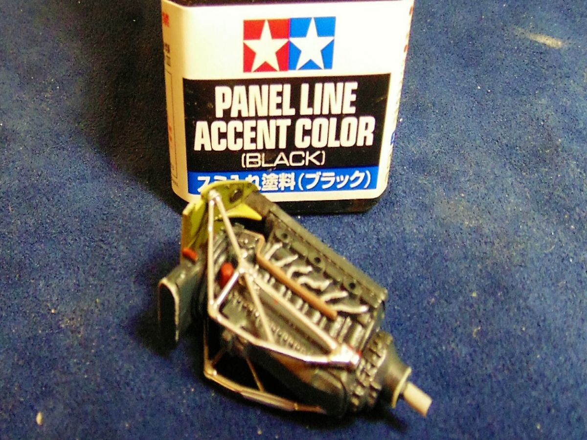
STEP TEN Gets us back to building and adding necessary details. The landing gear, as mentioned, were dry-fitted prior and a good thing because after a couple of clear coats, to seal the paint and decals, the slots now had a tighter fit. Hats to Italeri for adding the nice mechanical workings, separate spoked wheel rims and gear covers with good looking rivet and connection points. The two-part tires needed very little clean up so they painted easily and looked excellent after a pin wash with Tamiya Black Panel Line. And with the tail wheel in place the rest of model that needed it could have a black wash. Personally, I use mineral spirits to remove the unwanted pigment because if the look I'm going for is subtle then with that extra rub it can be achieved, again a personal choice. I've had first hand experience with machinery coming from overseas and know fish oil is used to keep parts from corroding. These aircraft may have gone through the same procedure, yet would have been washed down before assembly leaving some black residue, at least that's my logic behind the look.
STEP ELEVEN We'll skip because it gives the instructions for wheels up.
STEP TWELVE Has only two parts for me to add. One is a small pole in front of the cockpit where Italeri ask to be placed 15mm behind the back of the engine cowling, but it should read 5mm. The other part is a navigation light forward the antenna. I painted the bottom bright red and it looks really interesting after a dab of X-22 clear. Attacking it was not fun though, considering it's only a few mm long.
STEP THIRTEEN Simple shows open engine cowls which have already been completed.
STEP FOURTEEN Is where the entire model gets a few dull coats of Vallejo Premium mat varnish. I've found that reducing this product with ten drops of thinner to 30 drops of varnish works well for "me", but remember I live almost 6000 feet above sea level in a dry colder environment. Now the masks come off of the canopy and the rear-view mirror can be installed (which fell off during the photo shoot...ugh!) The photo etch fret also includes four grab handles for the pilot to open and close. I wanted to get this feature done and didn't add them. It's also nice that the pilot escape panel can be left open to show off the cockpit detail.
THE FINAL STEP Is the spinner and propellers. As previously mentioned, the pin emerging from the engine is to long and the engine itself sticks out to far beyond the nose. I simply shortened them and cemented since I've no desire to have the propellers turn.
CLOSING THOUGHTS
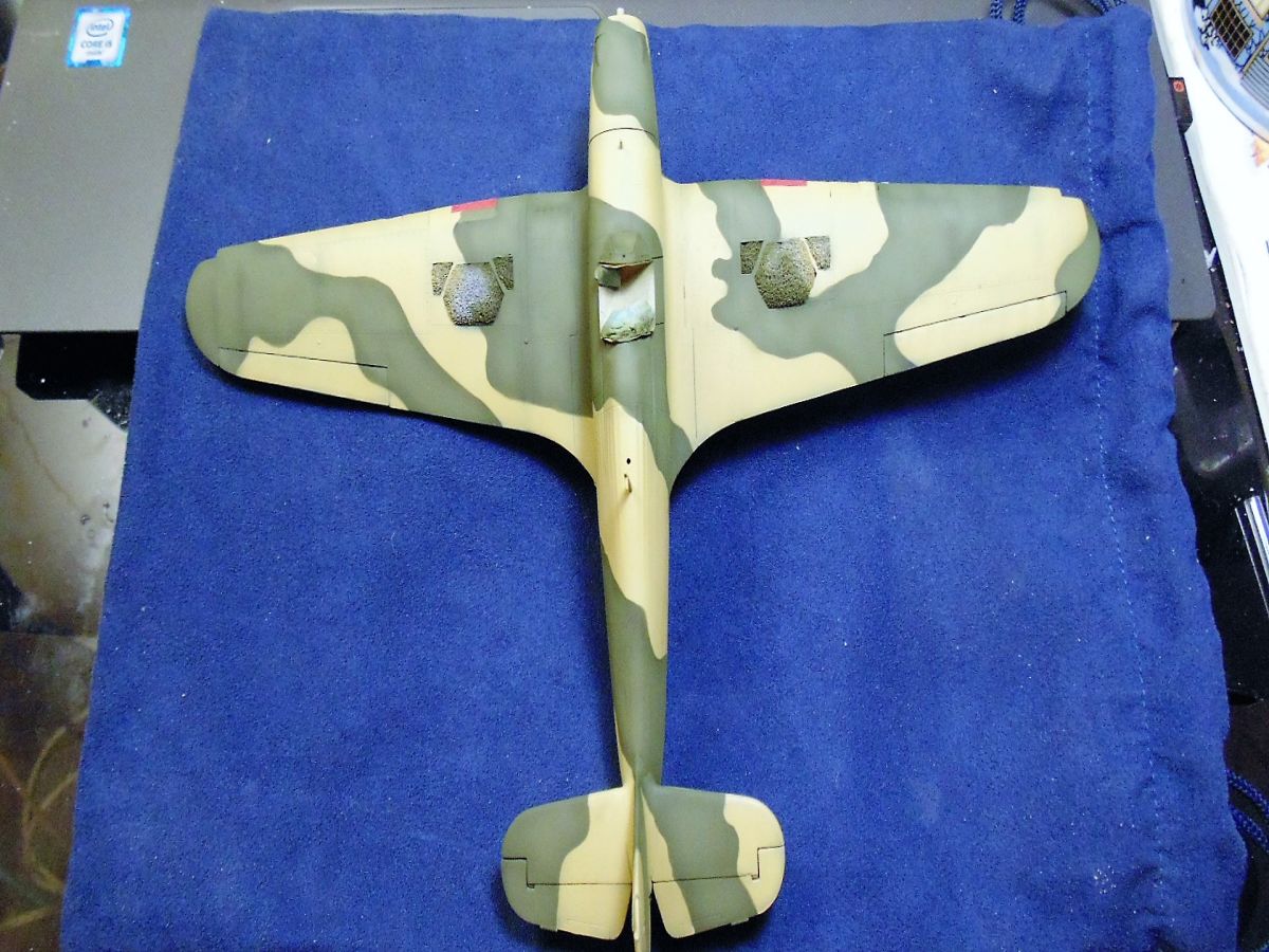
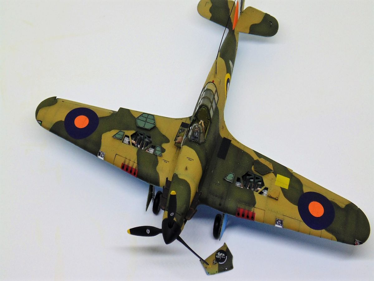
There is no doubt Italeri and RES-IM have a unique product to offer those interested in this subject matter. And while there is fair amount of thought and work to be done in order to create the end result, it isn't anything that's difficult, it simply takes time. When you consider how rare this combination is, I feel it demands such time and effort.CONCLUSION
And there you have it, my Feature Build of the 1/48 Scale Italeri Hawker Hurricane Mk.I Trop with RES-IM resin gun bays. I hope you've enjoyed the step by step account and most certainly thank you for staying this long through my process. Any comments or suggestions are always welcome.Special thanks to Italeri and RES-IM for supplying these samples for review and build.
To Maple Airbrush Supplies for the primer and SMS for the pigments and washes.
When you're at a retailer purchasing this kit, please mention you saw a review on KIT MAKER NETWORK


About the Author


FROM: ALBERTA, CANADA
H.G. Barnes is a former voice artist and sales/marketing executive. Currently ghost writing, he's recently published the first of many Science Fiction, Fantasy, Romance, and Adventure novels. He's been building model kits of every genre since memory to go along with his short stories, yet aircraft h...
Comments
Copyright ©2021 by HG Barnes. Images also by copyright holder unless otherwise noted. The views and opinions expressed herein are solely the views and opinions of the authors and/or contributors to this Web site and do not necessarily represent the views and/or opinions of AeroScale, KitMaker Network, or Silver Star Enterrpises. Images also by copyright holder unless otherwise noted. Opinions expressed are those of the author(s) and not necessarily those of AeroScale. All rights reserved. Originally published on: 2017-12-05 00:00:00. Unique Reads: 11457

WEB HOSTING BY


Copyright ©2021 AeroScale and Kitmaker Network, a subsidiary of Silver Star Enterprises
All Rights Reserved. Please read our Conditions of Use and Privacy Policy.
All Rights Reserved. Please read our Conditions of Use and Privacy Policy.