

1⁄48Supermarine Spitfire Mk.I Build
3
Comments
AERIALS
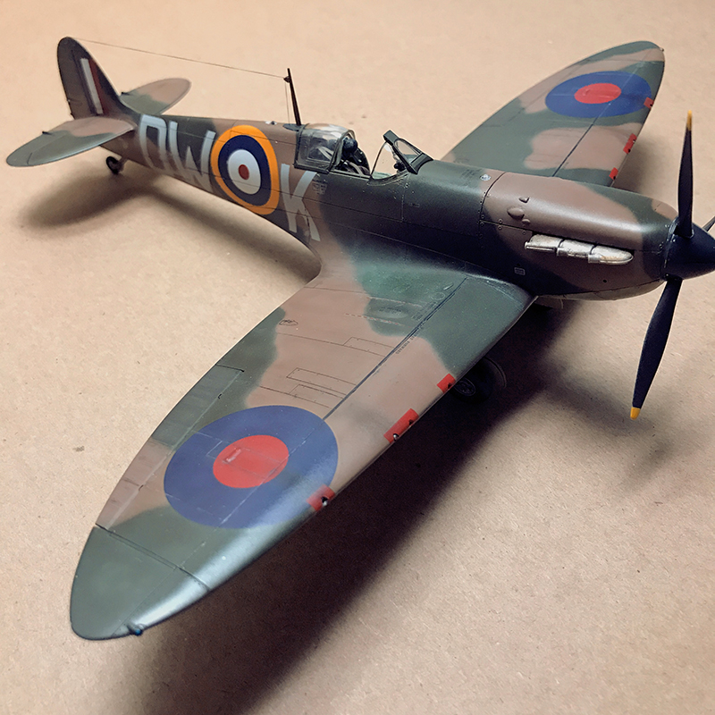
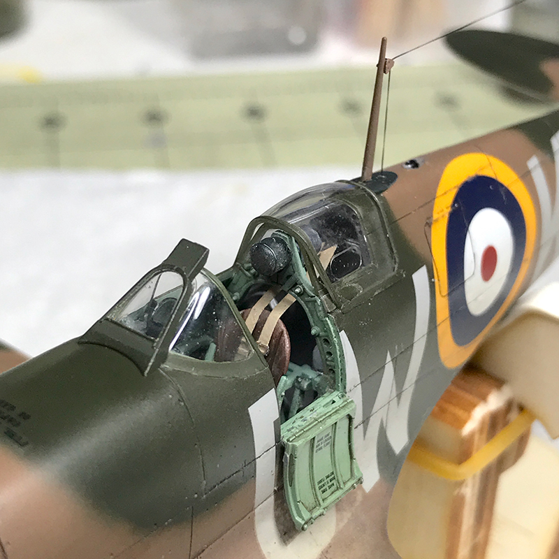
This is a fine time as any to discuss the radio aerials, since the manual, illustrations, poster and box art all end up as a mish-mosh of mixed signals and vague instructions. According to SpitfireSite.com, the earliest Spits were outfitted with the TR 9 HF (high frequency) radio transmitter/receiver. Its aerial ran up through the slim, round mast found on the earliest Spits (Version B), emerged at the top and ran back to an insulator at the top of the tail. That mast was soon replaced by the stronger, streamlined mast included for versions A and C. That aerial ran externally from the top of the fuselage up to the top of the mast, then back to the insulator on the tail.
In early summer 1940 (about the time of the Dunkirk evacuation and before the Battle of Britain) some new Spitfires were now equipped with the TR1133 VHF (very high frequency) transmitter/receiver. The shorter wavelengths of the TR1133 did not require the aerial wire that ran from the mast to the tail; the mast alone housed the antenna.
Finally, in late-September / early-October of 1940, Spitfires also began being fitted with IFF equipment. This equipment received ground radar signals and re-transmitted them, as SpitfireSite.com states, creating a distinctive bright blip on radar screens. The receiver and transmitter wires emerged from small insulators just in front of and slightly above the red centre spot of the fuselage roundels on both sides. The wires were anchored to the tailplane tips. (i.e. horizontal stabilizer)
None of the planes featured in this kit would have been outfitted with the IFF equipment, yet the final illustrations in the instructions (which show stencil placement) and the full-color poster all show the IFF wires in place. There are also dimples molded inside the fuselage where you would drill if you wanted to run the IFF wires, but the instructions correctly do not indicate that you should. But then again, the insulators where the IFF wires emerge on the outside of the fuselage are molded into the plastic, yet no mention is made that they should be filled.
If you want to build the early Version B from 1939 there is only one option; the round mast with the aerial from the top of the mast to the top of the tail. Version A (P9495) was built in April 1940 and was damaged and removed from service in August 1940. Version C (N3200) was also built in April 1940 and downed during Operation Dynamo (May 26 thru June 4 1940), long before IFF was issued. The restored/rebuilt N3200 at Duxford (Version C) has both the tapered mast and aerial wire. In all likelihood Version A would use the same configuration.
I have no doubt that there are far better historians here than me, so if you have differing evidence let us know in the comments of this article.
MOVING ON
After the cockpit is done, most of the build is over and the rest goes quickly. With Tamiya parts, there is never any question as to how they fit. There are always tabs, notches, or pins that locate them precisely, and youd really have to try to accidentally attach them in the wrong direction or, if there are pieces that mirror each other, on the wrong half. The wings, gear bays, wing tips, ailerons, horizontal stabilizers and rudder almost click into place.
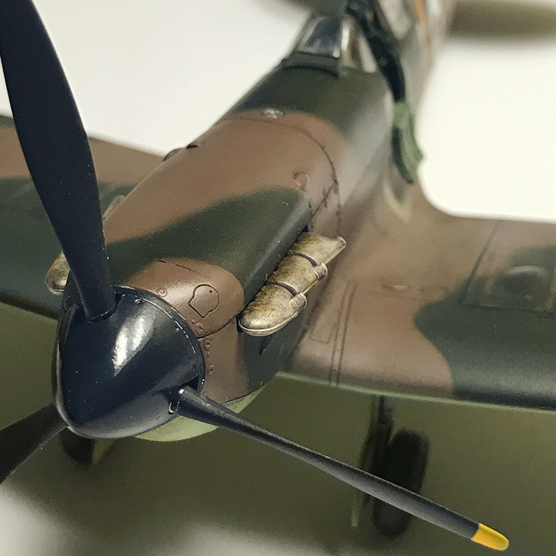
In the manual, the exhausts are built and installed right after the fuselage is closed, but there is no need to install them till the end after all the painting is done. The three piece exhausts that I praised in my in-box review ended up being a bit of a pain really. In order to keep from marring the weld lines on the exhaust with sprue gates, the two forward pipes are molded separately so the gates can be attached and hidden behind them. I found the fitment of the pipes poor, so filler had to be used around the small complex joint. By far, this was the biggest pain in building the kit.
The horizontal stabilizers are one piece that slides into the end of the tail then is capped by the rudder ensuring a perfect dihedral. Or so it would seem; despite the reinforcements inside the tail, our sample kit ended up with the vertical stabilizer cocked to port side, in turn throwing off the angle of the horizontal stabilizers.
The walls of the landing gear bays are made of three pieces each that fit together with astounding precision. In this photo they arent even glued together yet.
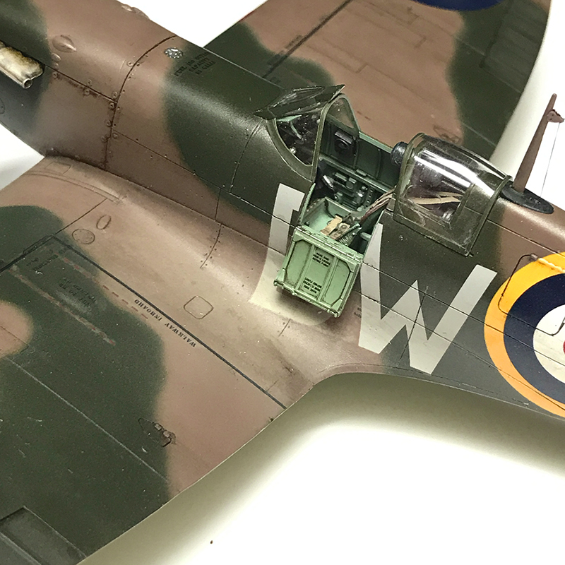
Dont forget to drill out the four holes on the bottom of the main wings before assembly. Just a touch of filler is required along the leading edge of the wings. And dont forget to paint the center of the wing since it is the cockpit floor.
The entire wing assembly fits snuggly to the bottom of the fuselage. I was a bit disappointed though at the wing roots since they didnt close up as tightly as the rest of the kit had lead me to believe. Same goes for where the rear of the wing pan butts the fuselage. Filling will be needed. Is Tamiya making me soft?
The radiator and oil cooler that mount under the wings go together wonderfully. Both have PE parts for the grills that have small tabs to help locate them perfectly. The larger radiator grills look great, but I wouldnt even bother with the small oil cooler grills. Once mounted, the openings are so small and dark that you cant see them unless you take a pen light and shine it inside.
One more handy tip: dont glue the chin to the fuselage until painting is finished. This will save you some tricky masking as the paint follows this seam.
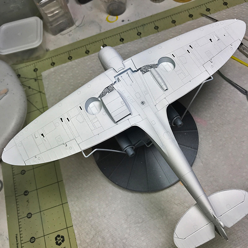
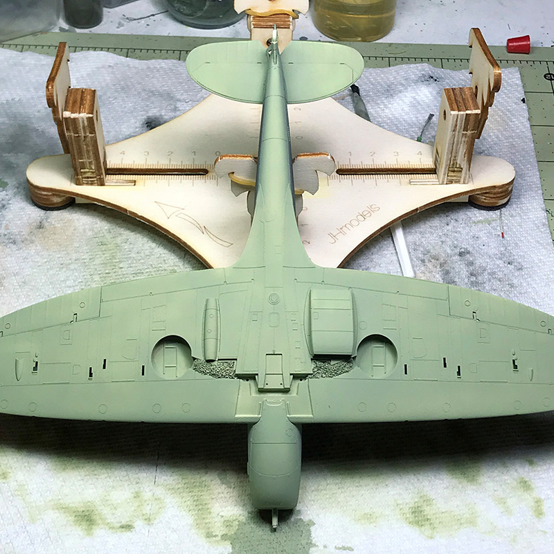
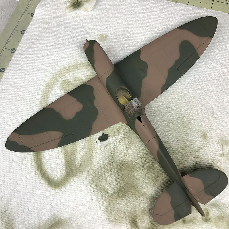
The next step in the manual is to install the wonderful one-piece landing gear, the panels that hide it, and the engine intake. But I didnt want to spray paint with the gear installed, so this is where I began painting. I sprayed the wheel wells with XF-16 Flat Aluminum (which has too much flake for my liking) and masked them with foam. Since I wanted to maintain the light color, I primed the belly with white Badger Stynylrez and sprayed some XF-57 Buff as pre-staining/shading. I cracked open my 22 year old bottle of XF-21 Sky and I was surprised that it mixed up fine. I thinned it about 1:1 with Mr. Leveling Thinner, and sprayed it onto a test mule. I was shocked that it sprayed fine too. I built up the belly, panels, gear covers and air intake with light coats and was very pleased with the tonal variations I got from the Buff. In hindsight, some grey pre-shading would have been a good idea.
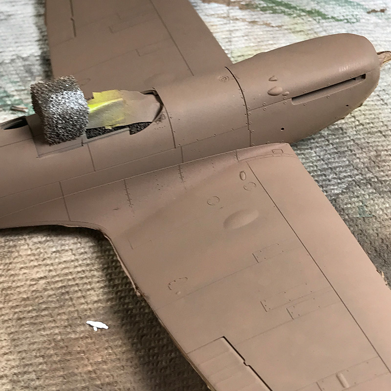
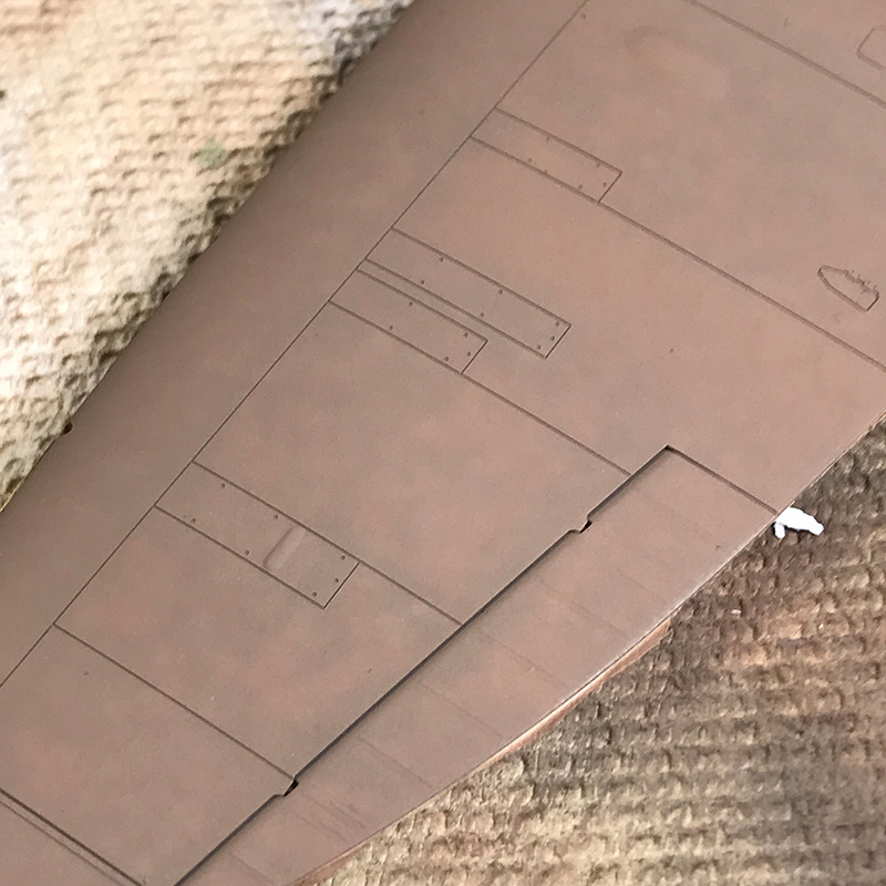
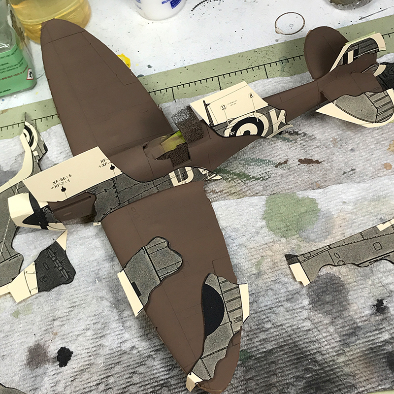
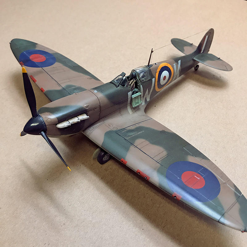
I primed the topside with black Stynylrez and mottled it with white, then I laid down the Dark Earth first. The manual gives us new formulas for the camouflage colors. Tamiya does not offer a paint that is officially RAF Dark Earth. They advise XF-52 Flat Earth in 5 parts to XF-49 Khaki in 1 part. Thats what I used and I like it. The Khaki lightens the Earth and yellows it a bit, though it might still be a touch too red. 2 parts Khaki might be even better.
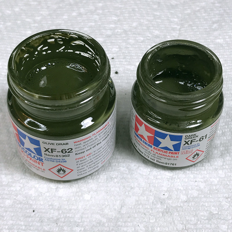
Tamiya does make an RAF Dark Green; XF-81. Along with XF-82 and 83 they make up the trio of RAF paints for the Ocean Grey/Green over Sea Grey scheme that would come later in the war. But this kit does not call out for XF-81. Perhaps RAF Dark Green paint changed later in the war? Instead they recommend a build of XF-62 Olive Drab in 5 parts darkened with XF-61 Dark Green in 1 part. Again I think the results were great.
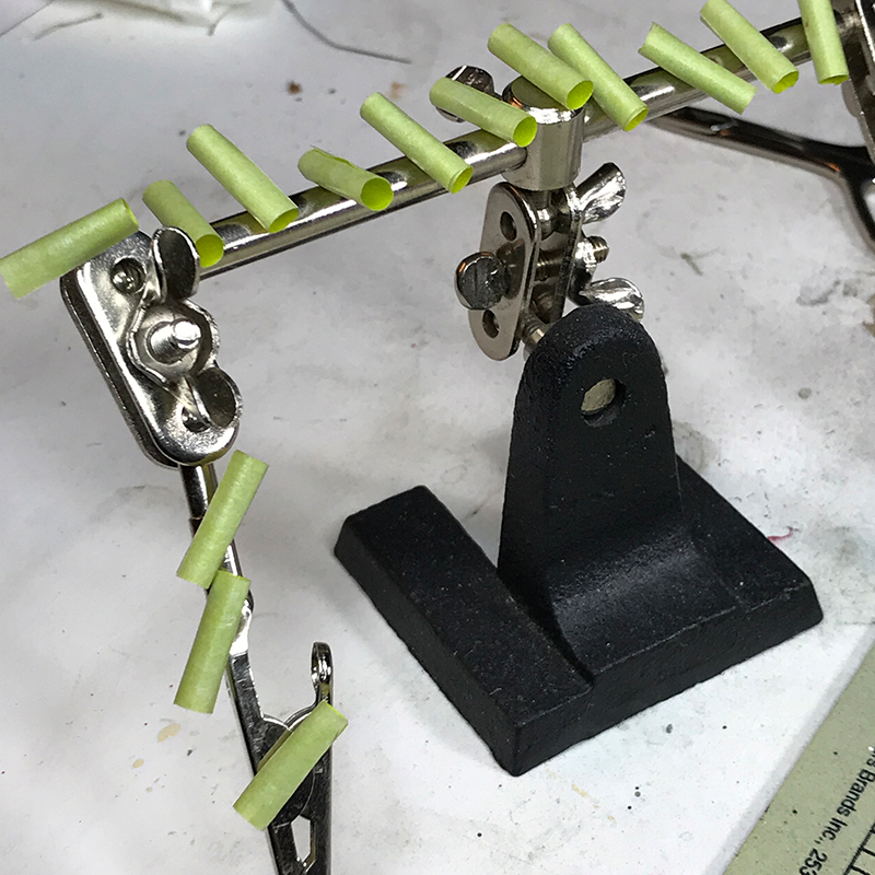
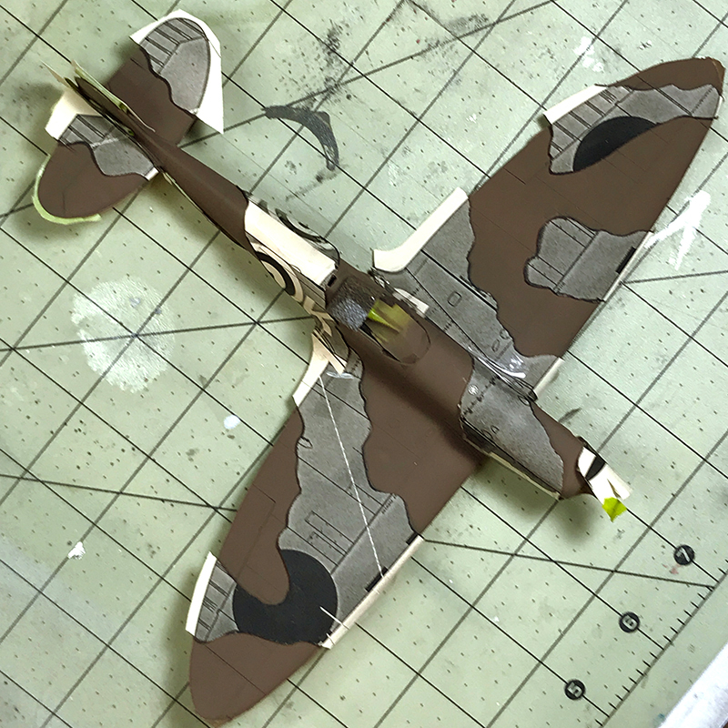
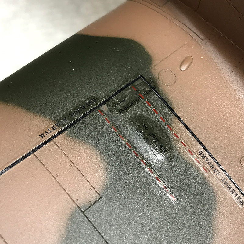
To mask the camo, I photocopied the 1:1 poster onto thick paper and cut it up for masks which I suspended above the surface with small rolled up tape loops. In the end I was pleased with the soft edge that the elevated masks produced, but the practice was tedious. Flat areas on the wings and rudder were easy to mask, but when you start trying to piece together masks that go up-and-over the fuselage, that are cut from three different drawing perspectives that meet at the top of the fuselage, the going quickly gets much harder. If someone out there makes reusable plastic or vinyl masks in 1/48 that can be used in the same way, they would be a useful investment if the 1/48 Spitfire is a subject you plan to return to.
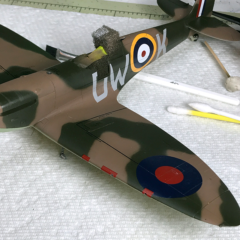
I clear coated it with X-22 Clear to seal it in. X-22 darkened the paint noticeably, not to my liking. Once sealed and dry I started the decaling. If you are going to use all the stencils there are around 50 to put down. Pay attention to both the manual and the color poster. The last diagrams in the manual show stencil placement that is common to all the versions in the kit. Additionally, there are other stencils indicated on the color sheet that pertain to the particular version you choose to build. And pay attention to which stencils may go over top of larger markings. This is not clearly shown in a few places; get ready to punt.
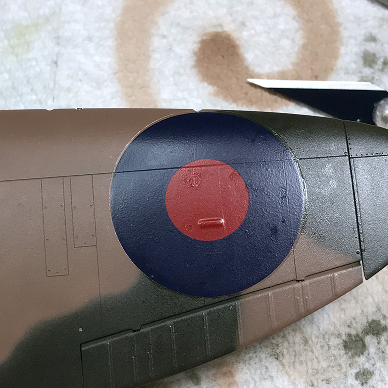
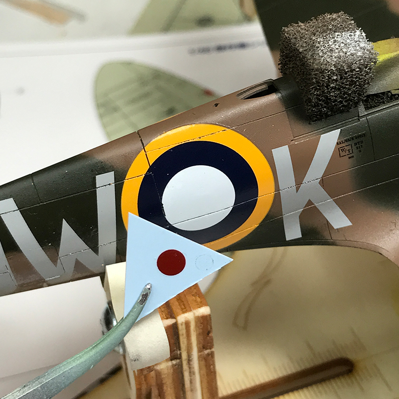
So there were really no surprises about the decals. They are typically thick Tamiya offerings. Based upon the excellence of the molds I have to believe that they know exactly what they are doing, that they have chosen the path of sturdy and predictable markings over something thinner yet prone to distortion or tearing. For they never once threatened to tear, or flop over on themselves. But surely there must be a happy medium? I used MicroSet and MicroSol during placement. MicroSol did help the roundels to settle down into the panel lines somewhat, but not as much as I wanted. Several applications were needed over the course of several nights, but it never did snug down over the mid-roundel ridge. I had to resort to lacquer thinner over those bumps and a few hatch hinges. It was pretty hot and I had to work quickly; apply it fast then walk away. Solvaset is stronger than MicroSol. Maybe it will serve you better.
And also, why in the world is the round center of the fuselage roundels printed separately?? Ive been wondering about this since I did the in-box review. I thought that I would have an Ah-HA moment when I realized Tamiyas brilliance. But no. No revelation has come. It must have something to do with printing registration.
In the end you are left to decide what to do with your very stand-up-proud decals. You can feel the ridge around them and definitely see it. And at the front of the wings you have several stencils that crossover. Double DOH!
You can let it go, walk away and move on. Or you can try to knock them down a peg. I did. I wanted to see if I could hide them at least a bit. I spent several nights applying multiple coats of Aquagloss around and over the decals, then sanding the edges flush with Tamiya 2000 grit sanding sponge. Once cured, Aquagloss sands beautifully and I was, in time, able to build up the edges enough to hide them pretty well. With a little more effort and time I think I could make them invisible, but I have to move on.
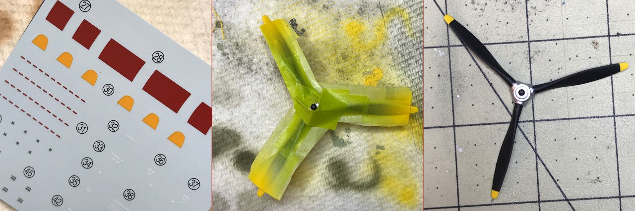
And this is pretty much where the review of the kit ends. Everything from this point on is optional; washing, weathering, and fading which have nothing to do with the kit itself. I will tell you that the instructions tell you to paint the inner hub of the prop, but dont bother. Once the nose cone is on you cant see inside at all. And they give you the option of using six decals for the yellow safety tips of the prop blades. But that seemed like a nightmare, so I masked and sprayed.
I would also like to share my favorite part of this kit; the marker light on the belly. I painted the inner shell with Model Master chrome enamel, and painted the inside of the lens with Tamiya Clear Orange. After unmasking it the lens shines lie a magic jewel from a fictional land. Its really too beautiful for a war subject, but i cant bring myself to dirty it up.
This is a fine time as any to discuss the radio aerials, since the manual, illustrations, poster and box art all end up as a mish-mosh of mixed signals and vague instructions. According to SpitfireSite.com, the earliest Spits were outfitted with the TR 9 HF (high frequency) radio transmitter/receiver. Its aerial ran up through the slim, round mast found on the earliest Spits (Version B), emerged at the top and ran back to an insulator at the top of the tail. That mast was soon replaced by the stronger, streamlined mast included for versions A and C. That aerial ran externally from the top of the fuselage up to the top of the mast, then back to the insulator on the tail.
In early summer 1940 (about the time of the Dunkirk evacuation and before the Battle of Britain) some new Spitfires were now equipped with the TR1133 VHF (very high frequency) transmitter/receiver. The shorter wavelengths of the TR1133 did not require the aerial wire that ran from the mast to the tail; the mast alone housed the antenna.
Finally, in late-September / early-October of 1940, Spitfires also began being fitted with IFF equipment. This equipment received ground radar signals and re-transmitted them, as SpitfireSite.com states, creating a distinctive bright blip on radar screens. The receiver and transmitter wires emerged from small insulators just in front of and slightly above the red centre spot of the fuselage roundels on both sides. The wires were anchored to the tailplane tips. (i.e. horizontal stabilizer)
None of the planes featured in this kit would have been outfitted with the IFF equipment, yet the final illustrations in the instructions (which show stencil placement) and the full-color poster all show the IFF wires in place. There are also dimples molded inside the fuselage where you would drill if you wanted to run the IFF wires, but the instructions correctly do not indicate that you should. But then again, the insulators where the IFF wires emerge on the outside of the fuselage are molded into the plastic, yet no mention is made that they should be filled.
If you want to build the early Version B from 1939 there is only one option; the round mast with the aerial from the top of the mast to the top of the tail. Version A (P9495) was built in April 1940 and was damaged and removed from service in August 1940. Version C (N3200) was also built in April 1940 and downed during Operation Dynamo (May 26 thru June 4 1940), long before IFF was issued. The restored/rebuilt N3200 at Duxford (Version C) has both the tapered mast and aerial wire. In all likelihood Version A would use the same configuration.
I have no doubt that there are far better historians here than me, so if you have differing evidence let us know in the comments of this article.
MOVING ON
After the cockpit is done, most of the build is over and the rest goes quickly. With Tamiya parts, there is never any question as to how they fit. There are always tabs, notches, or pins that locate them precisely, and youd really have to try to accidentally attach them in the wrong direction or, if there are pieces that mirror each other, on the wrong half. The wings, gear bays, wing tips, ailerons, horizontal stabilizers and rudder almost click into place.
In the manual, the exhausts are built and installed right after the fuselage is closed, but there is no need to install them till the end after all the painting is done. The three piece exhausts that I praised in my in-box review ended up being a bit of a pain really. In order to keep from marring the weld lines on the exhaust with sprue gates, the two forward pipes are molded separately so the gates can be attached and hidden behind them. I found the fitment of the pipes poor, so filler had to be used around the small complex joint. By far, this was the biggest pain in building the kit.
The horizontal stabilizers are one piece that slides into the end of the tail then is capped by the rudder ensuring a perfect dihedral. Or so it would seem; despite the reinforcements inside the tail, our sample kit ended up with the vertical stabilizer cocked to port side, in turn throwing off the angle of the horizontal stabilizers.
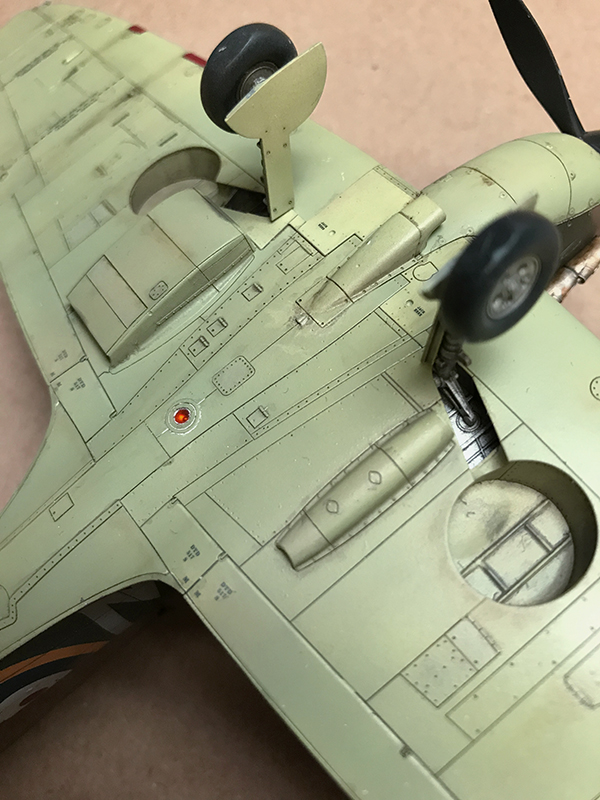
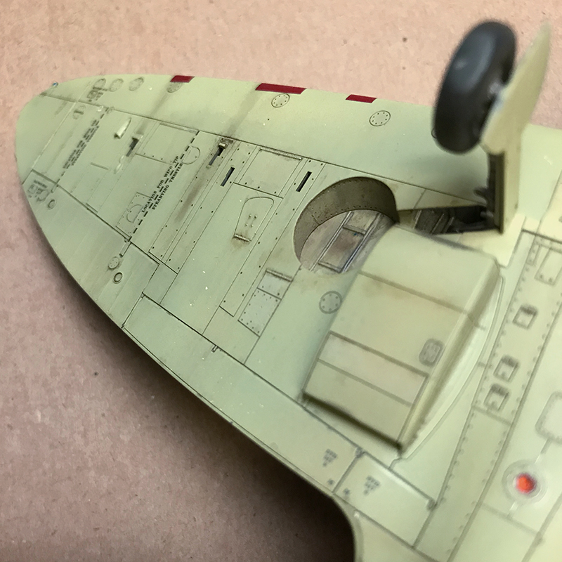
The walls of the landing gear bays are made of three pieces each that fit together with astounding precision. In this photo they arent even glued together yet.
Dont forget to drill out the four holes on the bottom of the main wings before assembly. Just a touch of filler is required along the leading edge of the wings. And dont forget to paint the center of the wing since it is the cockpit floor.
The entire wing assembly fits snuggly to the bottom of the fuselage. I was a bit disappointed though at the wing roots since they didnt close up as tightly as the rest of the kit had lead me to believe. Same goes for where the rear of the wing pan butts the fuselage. Filling will be needed. Is Tamiya making me soft?
The radiator and oil cooler that mount under the wings go together wonderfully. Both have PE parts for the grills that have small tabs to help locate them perfectly. The larger radiator grills look great, but I wouldnt even bother with the small oil cooler grills. Once mounted, the openings are so small and dark that you cant see them unless you take a pen light and shine it inside.
One more handy tip: dont glue the chin to the fuselage until painting is finished. This will save you some tricky masking as the paint follows this seam.
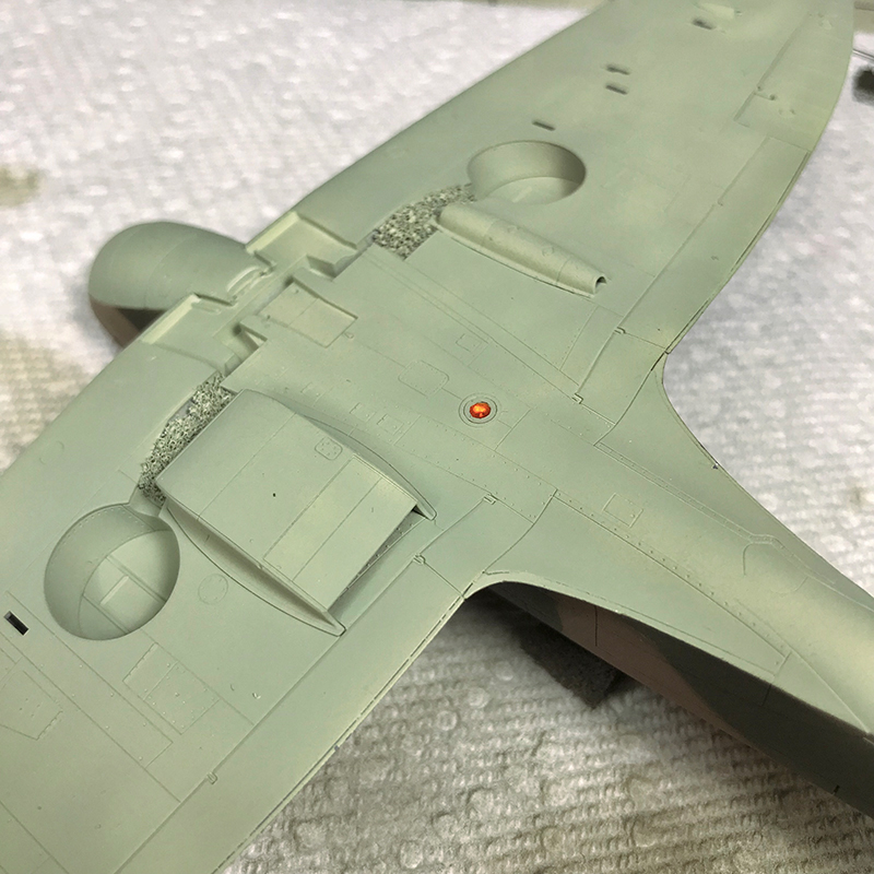
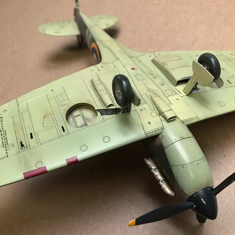
The next step in the manual is to install the wonderful one-piece landing gear, the panels that hide it, and the engine intake. But I didnt want to spray paint with the gear installed, so this is where I began painting. I sprayed the wheel wells with XF-16 Flat Aluminum (which has too much flake for my liking) and masked them with foam. Since I wanted to maintain the light color, I primed the belly with white Badger Stynylrez and sprayed some XF-57 Buff as pre-staining/shading. I cracked open my 22 year old bottle of XF-21 Sky and I was surprised that it mixed up fine. I thinned it about 1:1 with Mr. Leveling Thinner, and sprayed it onto a test mule. I was shocked that it sprayed fine too. I built up the belly, panels, gear covers and air intake with light coats and was very pleased with the tonal variations I got from the Buff. In hindsight, some grey pre-shading would have been a good idea.
I primed the topside with black Stynylrez and mottled it with white, then I laid down the Dark Earth first. The manual gives us new formulas for the camouflage colors. Tamiya does not offer a paint that is officially RAF Dark Earth. They advise XF-52 Flat Earth in 5 parts to XF-49 Khaki in 1 part. Thats what I used and I like it. The Khaki lightens the Earth and yellows it a bit, though it might still be a touch too red. 2 parts Khaki might be even better.
Tamiya does make an RAF Dark Green; XF-81. Along with XF-82 and 83 they make up the trio of RAF paints for the Ocean Grey/Green over Sea Grey scheme that would come later in the war. But this kit does not call out for XF-81. Perhaps RAF Dark Green paint changed later in the war? Instead they recommend a build of XF-62 Olive Drab in 5 parts darkened with XF-61 Dark Green in 1 part. Again I think the results were great.
To mask the camo, I photocopied the 1:1 poster onto thick paper and cut it up for masks which I suspended above the surface with small rolled up tape loops. In the end I was pleased with the soft edge that the elevated masks produced, but the practice was tedious. Flat areas on the wings and rudder were easy to mask, but when you start trying to piece together masks that go up-and-over the fuselage, that are cut from three different drawing perspectives that meet at the top of the fuselage, the going quickly gets much harder. If someone out there makes reusable plastic or vinyl masks in 1/48 that can be used in the same way, they would be a useful investment if the 1/48 Spitfire is a subject you plan to return to.
I clear coated it with X-22 Clear to seal it in. X-22 darkened the paint noticeably, not to my liking. Once sealed and dry I started the decaling. If you are going to use all the stencils there are around 50 to put down. Pay attention to both the manual and the color poster. The last diagrams in the manual show stencil placement that is common to all the versions in the kit. Additionally, there are other stencils indicated on the color sheet that pertain to the particular version you choose to build. And pay attention to which stencils may go over top of larger markings. This is not clearly shown in a few places; get ready to punt.
So there were really no surprises about the decals. They are typically thick Tamiya offerings. Based upon the excellence of the molds I have to believe that they know exactly what they are doing, that they have chosen the path of sturdy and predictable markings over something thinner yet prone to distortion or tearing. For they never once threatened to tear, or flop over on themselves. But surely there must be a happy medium? I used MicroSet and MicroSol during placement. MicroSol did help the roundels to settle down into the panel lines somewhat, but not as much as I wanted. Several applications were needed over the course of several nights, but it never did snug down over the mid-roundel ridge. I had to resort to lacquer thinner over those bumps and a few hatch hinges. It was pretty hot and I had to work quickly; apply it fast then walk away. Solvaset is stronger than MicroSol. Maybe it will serve you better.
And also, why in the world is the round center of the fuselage roundels printed separately?? Ive been wondering about this since I did the in-box review. I thought that I would have an Ah-HA moment when I realized Tamiyas brilliance. But no. No revelation has come. It must have something to do with printing registration.
In the end you are left to decide what to do with your very stand-up-proud decals. You can feel the ridge around them and definitely see it. And at the front of the wings you have several stencils that crossover. Double DOH!
You can let it go, walk away and move on. Or you can try to knock them down a peg. I did. I wanted to see if I could hide them at least a bit. I spent several nights applying multiple coats of Aquagloss around and over the decals, then sanding the edges flush with Tamiya 2000 grit sanding sponge. Once cured, Aquagloss sands beautifully and I was, in time, able to build up the edges enough to hide them pretty well. With a little more effort and time I think I could make them invisible, but I have to move on.
And this is pretty much where the review of the kit ends. Everything from this point on is optional; washing, weathering, and fading which have nothing to do with the kit itself. I will tell you that the instructions tell you to paint the inner hub of the prop, but dont bother. Once the nose cone is on you cant see inside at all. And they give you the option of using six decals for the yellow safety tips of the prop blades. But that seemed like a nightmare, so I masked and sprayed.
I would also like to share my favorite part of this kit; the marker light on the belly. I painted the inner shell with Model Master chrome enamel, and painted the inside of the lens with Tamiya Clear Orange. After unmasking it the lens shines lie a magic jewel from a fictional land. Its really too beautiful for a war subject, but i cant bring myself to dirty it up.
About the Author


FROM: PENNSYLVANIA, UNITED STATES
Like a thousand others here, I've returned to the sport after a 20 year hiatus, primarily building planes. The first kit I ever built with my dad was MPC's 1/16 Petty Charger with the clear body. I'd love to have that kit again. I am thrilled to see how the hobby has grown, and the generosity of its...
Comments

Hi William.Beautiful construction and with correct details.Best wishes. Christos.
APR 21, 2019 - 08:31 AM

Thanks Christos, I learned a lot about Spitfires while building this kit.
APR 23, 2019 - 06:26 AM
Hey everyone,
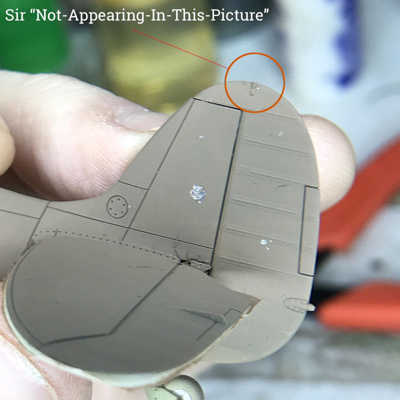
There is a paragraph I forgot to include during the Spitfire build. It goes along with the photo of the tail with a missing piece circled. Here is the explanation:
"And I have one last gripe. I hate when very fragile parts are molded right to the fuselage, thus daring you to break them off in the many hours of handling to follow. This kit is not immune. The radio wire insulator on the tail is one such part. It is fragile and wide-out in the open. I was hyper-aware of it, and managed to only bend it over once before painting began. While painting the belly, it snagged on my fleece, and I ripped it right off
never to be seen again."
APR 24, 2019 - 01:38 AM
Copyright ©2021 by Wiggus. Images also by copyright holder unless otherwise noted. The views and opinions expressed herein are solely the views and opinions of the authors and/or contributors to this Web site and do not necessarily represent the views and/or opinions of AeroScale, KitMaker Network, or Silver Star Enterrpises. Images also by copyright holder unless otherwise noted. Opinions expressed are those of the author(s) and not necessarily those of AeroScale. All rights reserved. Originally published on: 2019-04-18 00:00:00. Unique Reads: 15599

WEB HOSTING BY


Copyright ©2021 AeroScale and Kitmaker Network, a subsidiary of Silver Star Enterprises
All Rights Reserved. Please read our Conditions of Use and Privacy Policy.
All Rights Reserved. Please read our Conditions of Use and Privacy Policy.