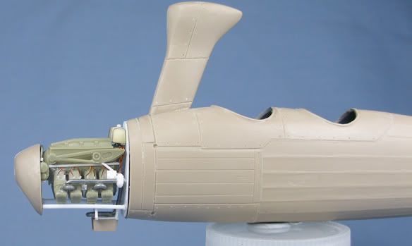
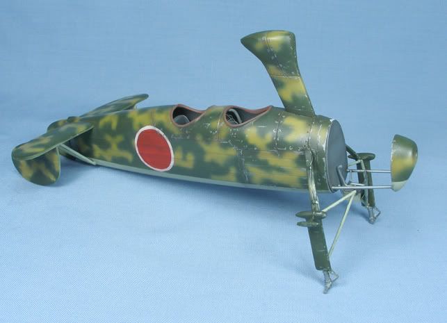
Thought I'd share a few quick progress pics of my latest project the 1/48 Kayaba KA-1 autogyro from AZ Models.

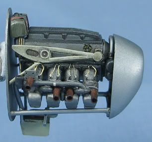
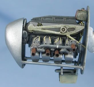
This little autogyro shares a unique (yet obscure) place in history as the worlds first operational autogyro. This little aircraft was operated by the Japanese in world war two from around mid 1942, and was used by both the Army and Navy for reconnaissance, artillery spotting and even anti-submarine warfare using depth charges (a sub kill is tentatively credited to a KA-1). These aircraft were operated from both land and light aircraft carriers. They were powered by license built copies of the German Argus AS-10C engine (same engine used on the Bf-108 and Fiesler Storch). Some 240 examples were built.
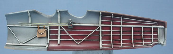
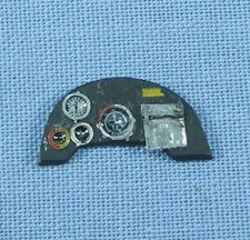
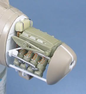
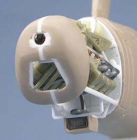
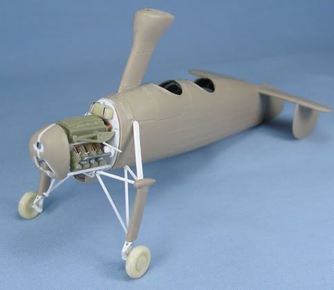
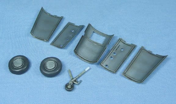
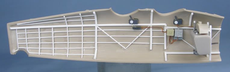
There are little to no references on this aircraft that I could find on the internet other than some grainy photos and line drawings. This didnt help me in working out how the cockpit should look. For the cockpit, the kit supplies some thick internal framing, a floor, two photoetch instrument panels that glue onto plastic backing, two resin seats, a resin throttle and a resin map case. The fuselage halves are marred with large ejector pins on the inside, the framing doesnt conform to the shape of the fuselage, the control columns look like truck axles and the instrument panels dont fit. Long story short I scratch-built the cockpit. As I have no references, this was an exercise in creative gismology.
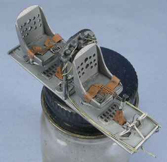
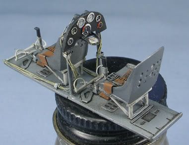
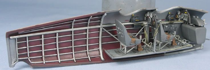
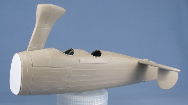
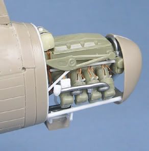
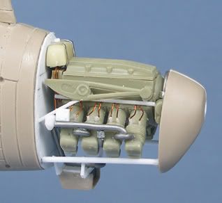
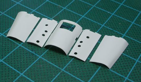
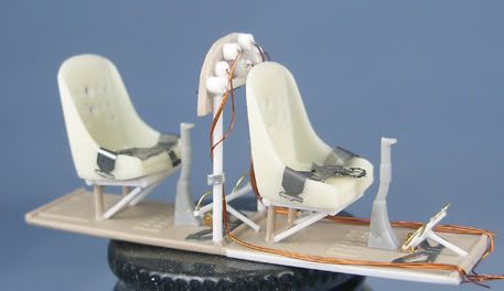
I filled and sanded the ejector pin marks in the fuselage halves, and made some framing from thin evergreen strip. I retained the cockpit floor, seats and plastic instrument panels sanded to fit. The seats had lightening holes drilled in them to more represent the usual Japanese style of aircraft seats, and the kit lap belts were used. Gauge backs for the rear instrument panel were added from plastic rod, and wiring from the instrument panel gauges was added from fine wire (no need for this on the front instrument panel obviously!). I retained the map case, glued in to the front cockpit (the instructions would have you glue it in to the back cockpit, however the observer sat in the front cockpit in this aircraft). I added throttle quadrants in both cockpits from the spares box. I figured that as this aircraft was a spotter aircraft that it likely had a small radio set so I rummaged through the spares box and added two small radios to the port observers cockpit. Remaining wiring was added from fuse wire. I also figured that the fuel tanks were likely around the centre of gravity, so I scratch-built the fuel and oil tank set up from the spares box, strip plastic and fine solder and will add them to the front of the cockpit. Again, no references for this but it looks convincing enough to me. Rudder pedals were scratch built and the control columns came from the spares box, as did the rest of the bits and pieces. You may notice the instrument panels have no gauges these will be added from a photoetched gauge set after painting.
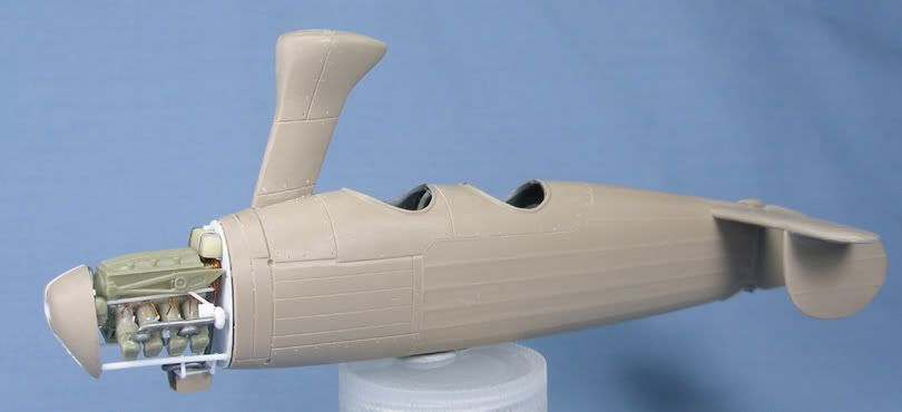
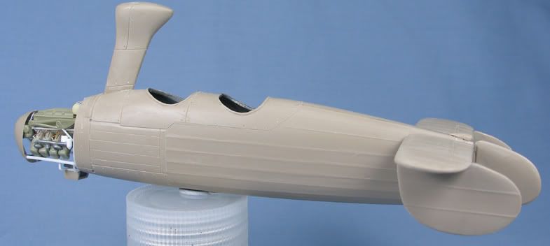
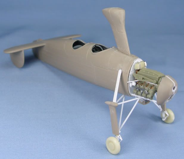
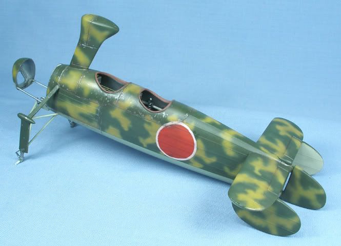
Here are some pics of it all dry fitted together.


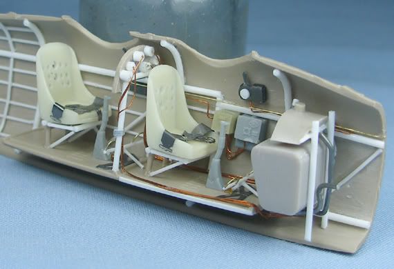
Next is on to painting the instructions say that the cockpit was painted dark grey given that I have no references to dispute or to prove that this is the case, I am still considering what colours I will paint the interior .. anyways
All feedback welcome!