

Hi guys
Has anyone out there seen a copy of this kit yet? If you have, what's it like - hopefully on a par with the Fulmar and Skua? As an Aussie I feel almost duty bound to pick one up (!), but given that the asking price is @$USD50, I want to do a bit of research first....It's been out for a few weeks now, but I haven't seen any reviews anywhere.
thanks, Brad
Hosted by Rowan Baylis
New 1/48 Special Hobby CAC-12 Boomerang

buggalugs

Joined: June 06, 2007
KitMaker: 135 posts
AeroScale: 115 posts
Posted: Friday, May 09, 2008 - 10:15 AM UTC

tculotta

Joined: January 15, 2008
KitMaker: 12 posts
AeroScale: 11 posts
Posted: Monday, May 12, 2008 - 01:02 AM UTC
Brad,
I have started building it and I love it. The cockpit has a good amount of detail. The engine is resin and well-detailed and it all connects so that everything from the prop hub through the cockpit is very well-detailed. I have started building it and you can track it here:
http://www.arcforums.com/forums/air/index.php?showtopic=152465
I expect to finish the engine this week and get the fuselage buttoned up. Given that it is a limited run kit, there is lots of test-fitting. I have had to slightly move or thin a few of the cockpit details so that the fuselage will close up properly.
I am enjoying it immensely. It appears to have been thoroughly thought-out by the designers and provides a lot of the fun and challenges I seek in building models. Highly recommended!
Regards,
Ted Culotta
buggalugs
Joined: June 06, 2007
KitMaker: 135 posts
AeroScale: 115 posts
Posted: Monday, May 12, 2008 - 01:23 AM UTC
Ted
Thanks - the kit looks great. And I love your build so far...That is one thread I am going to be keeping an eye on! What are the kit's decal options like? cheers Brad
Thanks - the kit looks great. And I love your build so far...That is one thread I am going to be keeping an eye on! What are the kit's decal options like? cheers Brad
tculotta
Joined: January 15, 2008
KitMaker: 12 posts
AeroScale: 11 posts
Posted: Monday, May 12, 2008 - 08:15 AM UTC
Brad,
Thank you for the feedback. Most of the credit goes to the kit.
The kit has 4 decal options:
R o - A46-62, "Sleepytime Girl," brown/green w/blue under, Perth, April, 1943
QE o S - A46-93, brown/green w/blue under, New Guinea, July, 1943
ZA o O - A46-95, brown/green w/blue under, New Guinea, December, 1943
MH o E, A46-52, green w/blue under, Camden, NSW, August, 1945
I have ordered the Earth Brown, Foliage Green, and Sky Blue from White Ensign, The decals are thin film, in good registration, with lots of stencils.
Regards
Ted Culotta

Merlin

#017


Joined: June 11, 2003
KitMaker: 17,582 posts
AeroScale: 12,795 posts

Posted: Monday, May 12, 2008 - 11:03 AM UTC
Hi Ted
LOL! What can I say? Submit your build / review here too! I have the kit on order, but you'll obviously have weeks' advantage on me!
To everyone: You all have to remember - this is your site - the Reviews section should reflect what you are building. We can never have too many writers telling us about the kits they have (both new and old) completed or on the workbench...
All the best
Rowan

tculotta
Joined: January 15, 2008
KitMaker: 12 posts
AeroScale: 11 posts
Posted: Monday, May 12, 2008 - 11:56 PM UTC
Rowan,
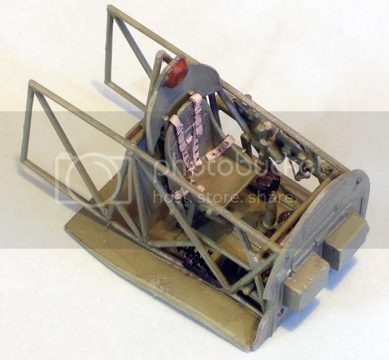
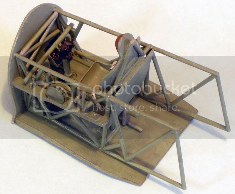
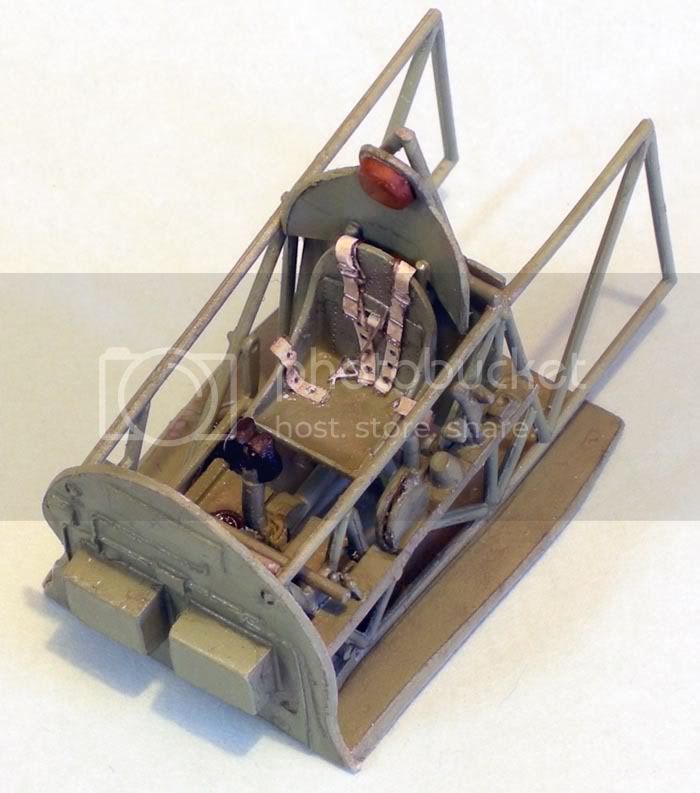
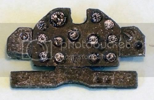
I'd be happy to. I'll post here what I post on ARC (I started it there because I decided to build it as part of a PacAir group build.) Here's what I have so far. The cockpit as you see it here is actually assembled from over 40 pieces. The instrument panel has not been added yet as its fit may present a small issue. On the panel, the raised area in the faces of the dials was a little soft for drybrushing, so I added Mike Grant instrument decals that are not exactly what the instruments were on the prototype, but they work. I also added one to what I presume is the compass, located between and slightly above the pedals. Everything from the engine back through the cockpit will be one assembly that is then added to the fuselage. The engine as shown here is after I glued the cylinders to the basic hub. Since this photo was taken, I have drilled holes for wiring (the kit does not address the wiring - one of its few shortcomings.) I'll likely finish the engine up today or tomorrow and post some additional pictures. You may note that the center of the engine looks white; the prop hub was included as part of the resin casting, but was deformed. I decided to snip it off and create my own mechanism that allows the prop to spin freely. I'll be drilling a hole and using two segments of hypo tubing, one nested in the other, to create a freely spinning prop.
Cheers,
Ted Culotta
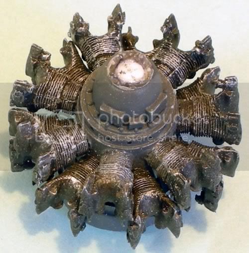
Merlin
#017
Joined: June 11, 2003
KitMaker: 17,582 posts
AeroScale: 12,795 posts
Posted: Tuesday, May 13, 2008 - 07:44 PM UTC
Nice one Ted
Your build is looking great! I've just heard from Modelimex that my kit should be here next week, so I'll link my Review to your pics.
How about submitting your finished Boomerang as a Feature? It'd be the perfect subject to grab attention on the Frontpage!
All the best
Rowan
Your build is looking great!
I've just heard from Modelimex that my kit should be here next week, so I'll link my Review to your pics.How about submitting your finished Boomerang as a Feature? It'd be the perfect subject to grab attention on the Frontpage!
All the best
Rowan

youngc
Joined: June 05, 2007
KitMaker: 2,166 posts
AeroScale: 105 posts

Posted: Wednesday, May 14, 2008 - 03:07 AM UTC
Amen

buggalugs
Joined: June 06, 2007
KitMaker: 135 posts
AeroScale: 115 posts
Posted: Wednesday, May 14, 2008 - 11:09 PM UTC
Well, I've finally bitten the bullet and ordered my copy of the kit - will hopefully pick it up at my local club's annual comp the weekend after next - might have to post my build here as well, once I pick up a ref or two...cheers Brad
tculotta
Joined: January 15, 2008
KitMaker: 12 posts
AeroScale: 11 posts
Posted: Thursday, May 15, 2008 - 01:13 AM UTC
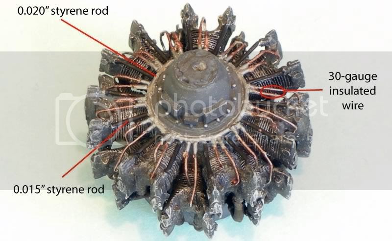
I finished up the engine last evening. Here are some photos along with some text describing the changes I made. Just to recap, the main part of the engine and cylinders are resin, as shown above. The frame, exhaust ring, and individual exhausts are styrene parts. There is no consideration for the ignition wires, so that is up to the modeler. I drilled holes in the cylinders for the wires. I started the detailing by adding the rods. The photo below illustrates the work. The rods are 0.015" styrene. The ring around the hub was created from 0.020" styrene rod, as noted. I wrapped it around a round paintbrush handle and ran scalding hot tap water over it followed by cool water. That "set" the circular shape to make it easier to glue around the engine hub. I affixed the ring to the top face of the rods with liquid cement (I use MEK) and to the face of the hub with ACC. The wires themselves are 30-gauge insulated wire from Radio Shack. I stripped the insulation except for a small amount that was left at the end. I inserted the ends of the wire into the holes in the cylinders and then butt-glued the end with the small piece of insulation to the face of the ring with ACC. After I finished these details, I painted them. The ring and bits of insulation, along with the nuts on the hub, were painted silver (I used Floquil Old Silver.) The rods were painted flat black. The wires were painted a copper color that I have kicking around here in an unlabeled jar.
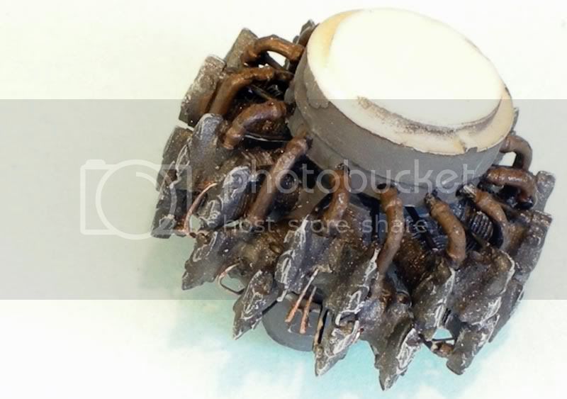
Next, I turned my attention to the intakes and exhausts. The intakes are bent at 90 degrees. These were simply glued in place, as shown. Then I turned my attention to the exhausts. To attach the exhausts, I first had to glue the engine to the frame, which was relatively easy, as there is a notch to align everything. I also glued the rear of the engine on the other side of the frame. Once these were in place, I started to test fit the exhausts. I found that the longer of the two types were woefully short, meaning that they did not span the distance between the exhaust ring and the front bank of engine cylinders. To solve this problem, I snipped off part of the "pipe" and then drilled a hole in the back of the remaining bit. I inserted a length of styrene rod into the hole and glued it in place. I test fitted this assembly in place and trimmed the rod to length and affixed it with ACC. I repeated this for the remaining long pipes. I then painted all the exhausts. The color is a 50/50 mix of Model Master Gunmetal and Leather. One is enamel and the other is lacquer, but there appear to be no problems.
After this was completed, I did some test-fitting and found that the completed engine is way too wide for the inside of the model. So..... I took my Dremel and carefully removed material from the inside of the engine area until I could see things getting thin (I held the model up to a strong light to see the "thin" areas.) This improved things, but not enough. I then had to file material from the outside edges of the cylinders. I can now get the fuselage "closed" around the engine, but it took some work. That's not unexpected when you mix resin and plastic in a short run kit, though.
Next, I'll glue the fuselage together.....
Here are the photos.
Ted Culotta
tculotta
Joined: January 15, 2008
KitMaker: 12 posts
AeroScale: 11 posts
Posted: Sunday, May 18, 2008 - 01:49 AM UTC
More progress....
I started the process of gluing the fuselage together by adding the interior details in bits rather than one large assembly as shown in the instructions. There is just too much to do it all at once and not have joints between large assemblies glued at small points coming undone.
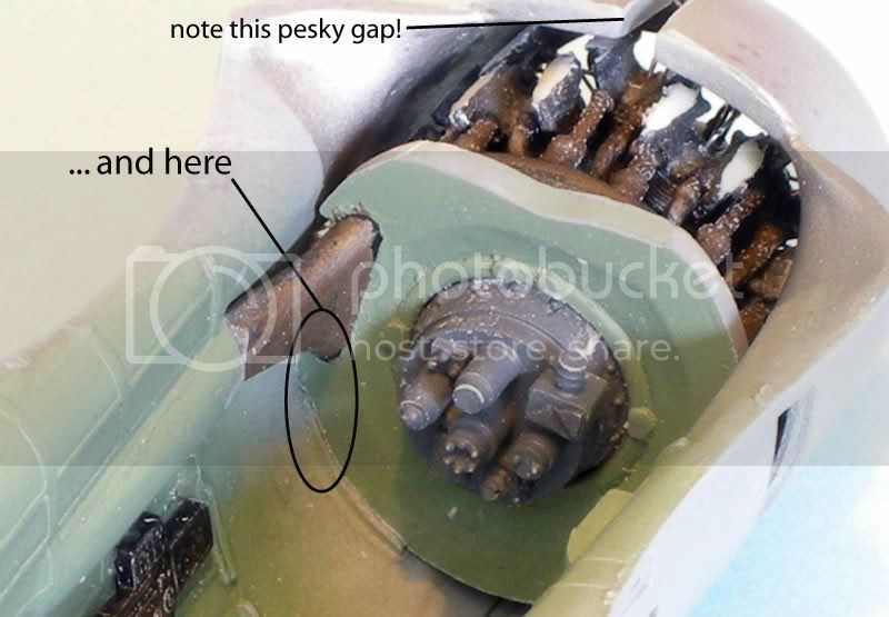
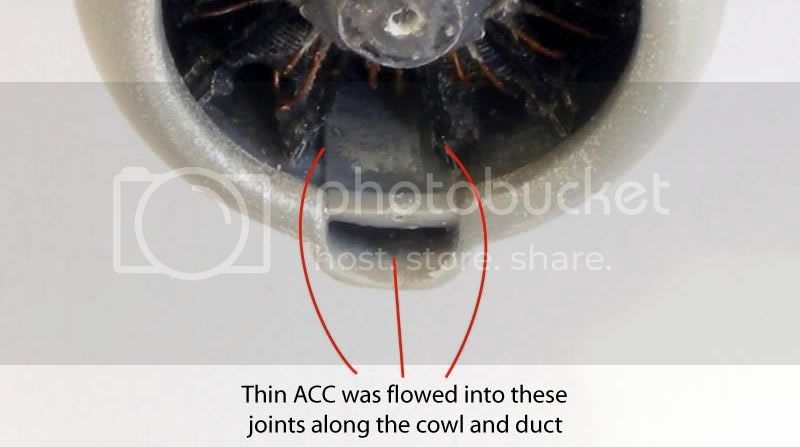
I began by gluing the engine assembly into the fuselage at two points. This provided two benefits - it helped to fix the engine in place with proper alignment. The other benefit is that this allowed me to focus on getting a small area correct rather than a large one where I couldn't properly pay attention to everything all at once (strong hint - when building limited run kits, do things in small manageable bites rather than large chunks!) I left the cowl/fuselage areas above and below the engine unglued. I then glued the rear of the fuselage together, still leaving the areas around the cowl "loose." Finally, I glued the top joint from the cockpit to the front of the cowl. This is a testy joint that will not want to stay together if any pressure is put on it. To fix it in place, I added the piece that completes the duct that runs above the engine. Once this had dried, I added small amounts of thin ACC to the inside of the upper cowl/fuselage and duct & upper cowl/fuselage joints. This helped to strengthen what was a rather tenuous joint. I left the bottom cowl joint unlgued as this would not be glued until I had worked out most of the wing/fuselage fit issues.
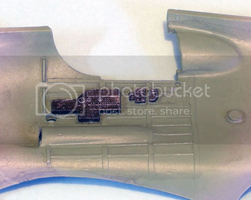
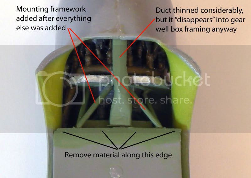
I turned my attention to the tasks needed to add the wings to the fuselage. I had left the lower cowl joint unglued to allow me some wiggle room to add and remove the cockpit assembly as needed for test fitting. I found that the cockpit itself present no fit issues. However, the duct from the engine area to the firewall would not fit. Also, the wheel well main spar and the bottom of the cockpit assembly were a little tight. I filed a LOT of material from the duct. The bad news is that it doesn't look very good. The good news is that there is an etched box structural member in the wheel well and the duct fairs into it quite nicely, making it look like that's its natural state. I also found it necessary to remove material from the main wheel well spar and the bottom of the cocpkit assembly. The photo of the wheel spar was taken after I had already glued the wings and fuselage together - I got a little absentminded. After I was convinced that these areas would not present any major problems, I added the cockpit for a final time and glued the lower cowl together, followed by the same thin ACC treatment for strength. To finish things up, I added the duct that I had vigorously filed. As a final touch, I added the engine/firewall mounts (the spindly looking 'W' shaped parts.) It was much easier than I had envisioned to thread them into the space between the engine and cockpit and line them up. Now is a good time to say that if you have this kit, I recommend that you remove these, all cockpit sidewall details, gear legs, and any other small or fragile bits from the main sprues and put them into baggies. My kit suffered much damage, both in transit and a small amount in handling because the sprues seemed to have separation anxiety. What I did was to remove the parts along with segments of sprue to aid in handling and identification.
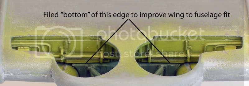
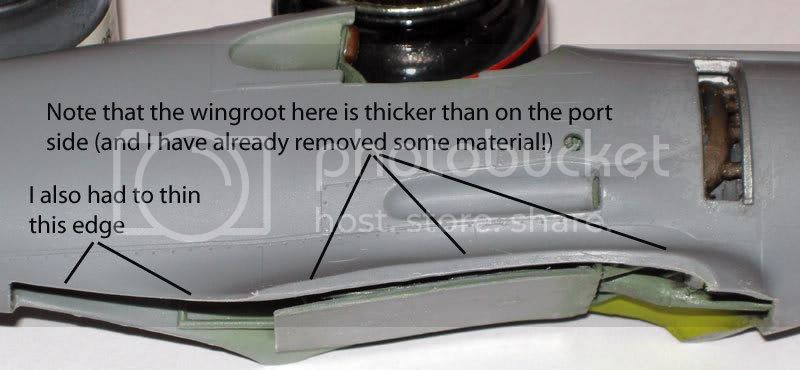
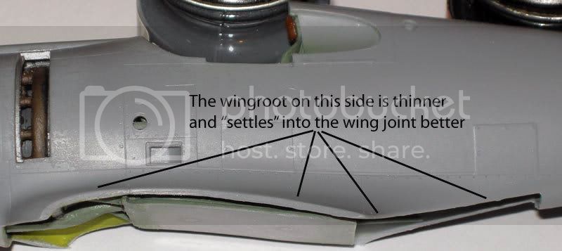
After I had all of the details nailed down, I began to play with the wings and fuselage in earnest. I found that the bottom edges of one side of the fuselage were significantly thicker than the other, creating MAJOR problems when test-fitting the two major assemblies. I found that by removing material from the lower edges, I was able to dramatically improve the fit, to the point that the majority of the fuselage/wingroot will be putty-free. There are a couple areas that will need some filling. The first is the fine edge where the wingroot meets the fuselage. This area is noticeably wider on the wing part than on the fuselage. The second area is a gap between the wing and fuselage just in front of the wingroot/fuselage area described above. The filing dust will help wit hthe ACC filler, so I have left it in place. I will also need to rescribe some lines on the underside where they do not meet.

I started the process of gluing the fuselage together by adding the interior details in bits rather than one large assembly as shown in the instructions. There is just too much to do it all at once and not have joints between large assemblies glued at small points coming undone.
I began by gluing the engine assembly into the fuselage at two points. This provided two benefits - it helped to fix the engine in place with proper alignment. The other benefit is that this allowed me to focus on getting a small area correct rather than a large one where I couldn't properly pay attention to everything all at once (strong hint - when building limited run kits, do things in small manageable bites rather than large chunks!) I left the cowl/fuselage areas above and below the engine unglued. I then glued the rear of the fuselage together, still leaving the areas around the cowl "loose." Finally, I glued the top joint from the cockpit to the front of the cowl. This is a testy joint that will not want to stay together if any pressure is put on it. To fix it in place, I added the piece that completes the duct that runs above the engine. Once this had dried, I added small amounts of thin ACC to the inside of the upper cowl/fuselage and duct & upper cowl/fuselage joints. This helped to strengthen what was a rather tenuous joint. I left the bottom cowl joint unlgued as this would not be glued until I had worked out most of the wing/fuselage fit issues.
I turned my attention to the tasks needed to add the wings to the fuselage. I had left the lower cowl joint unglued to allow me some wiggle room to add and remove the cockpit assembly as needed for test fitting. I found that the cockpit itself present no fit issues. However, the duct from the engine area to the firewall would not fit. Also, the wheel well main spar and the bottom of the cockpit assembly were a little tight. I filed a LOT of material from the duct. The bad news is that it doesn't look very good. The good news is that there is an etched box structural member in the wheel well and the duct fairs into it quite nicely, making it look like that's its natural state. I also found it necessary to remove material from the main wheel well spar and the bottom of the cocpkit assembly. The photo of the wheel spar was taken after I had already glued the wings and fuselage together - I got a little absentminded. After I was convinced that these areas would not present any major problems, I added the cockpit for a final time and glued the lower cowl together, followed by the same thin ACC treatment for strength. To finish things up, I added the duct that I had vigorously filed. As a final touch, I added the engine/firewall mounts (the spindly looking 'W' shaped parts.) It was much easier than I had envisioned to thread them into the space between the engine and cockpit and line them up. Now is a good time to say that if you have this kit, I recommend that you remove these, all cockpit sidewall details, gear legs, and any other small or fragile bits from the main sprues and put them into baggies. My kit suffered much damage, both in transit and a small amount in handling because the sprues seemed to have separation anxiety. What I did was to remove the parts along with segments of sprue to aid in handling and identification.
After I had all of the details nailed down, I began to play with the wings and fuselage in earnest. I found that the bottom edges of one side of the fuselage were significantly thicker than the other, creating MAJOR problems when test-fitting the two major assemblies. I found that by removing material from the lower edges, I was able to dramatically improve the fit, to the point that the majority of the fuselage/wingroot will be putty-free. There are a couple areas that will need some filling. The first is the fine edge where the wingroot meets the fuselage. This area is noticeably wider on the wing part than on the fuselage. The second area is a gap between the wing and fuselage just in front of the wingroot/fuselage area described above. The filing dust will help wit hthe ACC filler, so I have left it in place. I will also need to rescribe some lines on the underside where they do not meet.
buggalugs
Joined: June 06, 2007
KitMaker: 135 posts
AeroScale: 115 posts
Posted: Monday, May 19, 2008 - 02:04 AM UTC
Hi Ted
This is a fascinating build log - your photos and explanations are great, and I will definitely be referring to them when I build my kit. Sounds like you are really having to use some of those "basic modelling skills"! Out of interest, what camera and settings are you using? Your close-ups are really, well, close-up, much better than I have been able to achieve. Looking forward to the next installment, cheers Brad
This is a fascinating build log - your photos and explanations are great, and I will definitely be referring to them when I build my kit. Sounds like you are really having to use some of those "basic modelling skills"! Out of interest, what camera and settings are you using? Your close-ups are really, well, close-up, much better than I have been able to achieve. Looking forward to the next installment, cheers Brad
Merlin
#017
Joined: June 11, 2003
KitMaker: 17,582 posts
AeroScale: 12,795 posts
Posted: Monday, May 19, 2008 - 08:03 AM UTC
Hi Ted
It's looking excellent! My Boomerang has just arrived, so I'll prepare a basic In-Box review to tie in with your Full-Build.
All the best
Rowan
It's looking excellent! My Boomerang has just arrived, so I'll prepare a basic In-Box review to tie in with your Full-Build.
All the best
Rowan

Phantom2

Joined: April 18, 2006
KitMaker: 708 posts
AeroScale: 678 posts
Posted: Tuesday, May 20, 2008 - 07:08 AM UTC
Hi Ted!
Your article about the little Boomerang made me decide that I had to have one too!
I have always loved this tubby little fighter, ever since I built the old Airfix kit as a youngster.
Could never have dreamed that anyone would do a 1/48 Boomerang kit, neither could i believe that anyone would do a 1/48 J-35 Draken either!
Luckily I have been proved wrong two times now, I really don´t mind having wrong about such lovley aircrafts!
Now I have my Boomerang on order and are waiting eagerly and reading your build-blog with great interest.
You should really make a feature of it!
It would be great, and by the way, you have done most of the work already!
Cheers!
Stefan E
tculotta
Joined: January 15, 2008
KitMaker: 12 posts
AeroScale: 11 posts
Posted: Wednesday, May 21, 2008 - 01:45 AM UTC
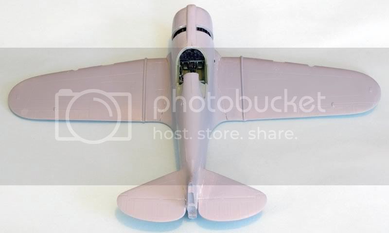
I have everything together and all of the areas that need to be filled and sanded are done. I need to go back and do some rescribing now. I have a sewing needle in a pin vise that I use to start the lines and then I use the Mission Models scriber tool to finish them up. I use Dymo tape for the straight lines and the etched scribing tool from Techstar for various shapes. The photos show some "gaps." These are actually gaps that have been filled and sanded, but appear as gaps to the naked eye (and camera) because I fill with ACC, and that is clear, meaning that gaps end up looking "unfilled." By holding the model with the gap line at an oblique angle to a light source, the surface of the model reflects the light, thereby allowing one to see whether the seam is smooth or needs improvement. When using the ACC, I add it with the tip of a straight pin, guiding it along the seam. I let it dry for no more than about 5 minutes, then add some drops of water to the seam, and then wet sand with progressively finer grades of paper. if you let the ACC sit too long, it becomes harder than the styrene, making it difficult to achieve a smooth seam, as the ACC and styrene are removed by the sandpaper at different rates due to their differing hardnesses.
In the photo on the underside of the aircraft, there is a white oval spot between where the wings fair into the fuselage. This is a combination of styrene and Mr. Surfacer 1000. There was an oval-shaped hole there that the kit advises the modeler to fill. Why it is there in the first place, I do not know - maybe for a forthcoming CA-13 (?)
Also, all of the colors that you see that I have used are based upon callouts by restorer, historian and modeler, Richard Hourigan as posted by Red Roo Models on their website. Paint matches are a little easier now as White Ensign has RAAF paints in their line (although there is a slight delay in getting them right now as they catchup from a backlog due to an employee injury a few months back.) That delay may mean that this sits on the shelf finished, but unpainted, until the paints arrive from WEM.
I have included a couple of shots showing the dash in the cockpit since I had not added that when the other cockpit photos were taken.
Regarding the camera question, I use a Nikon Coolpix P5000. It's a high end point and shoot, with full manual capabilities (more than my old Nikon F series cameras) and it allows extreme closeups. Its only drawback if one is seeking an all-around camera (e.g. outside the realm of model photos) is that there is a delay between when you depress the shutter and when the image is captured, rendering it effectively useless if one has young children, as I do - they rarely stay in the same place longer than a millisecond.
More soon.....
Cheers,
Ted Culotta
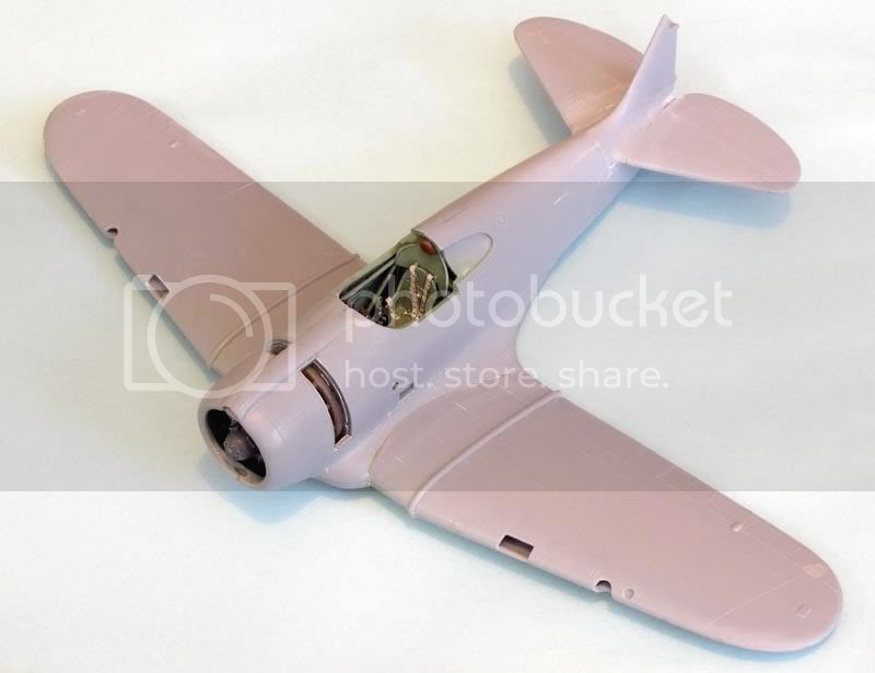
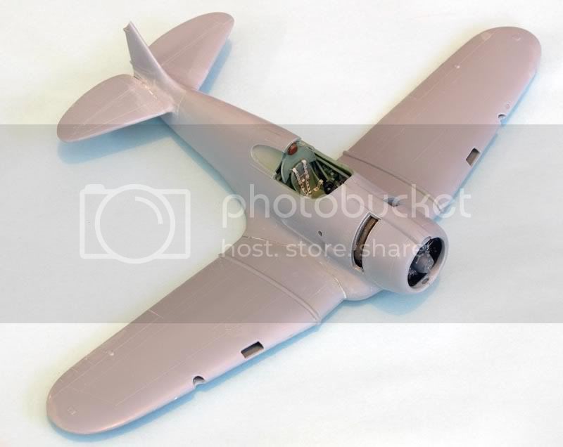

Blurto
Joined: April 03, 2006
KitMaker: 3 posts
AeroScale: 2 posts
Posted: Thursday, January 14, 2010 - 11:27 PM UTC
Ted,
does this thread continue? I'm building the kit and your efforts have been a big help. I'd like to see your finished product.
Cheers Barry.
does this thread continue? I'm building the kit and your efforts have been a big help. I'd like to see your finished product.
Cheers Barry.
 |

WEB HOSTING BY


Copyright ©2021 AeroScale and Kitmaker Network, a subsidiary of Silver Star Enterprises
All Rights Reserved. Please read our Conditions of Use and Privacy Policy.
All Rights Reserved. Please read our Conditions of Use and Privacy Policy.