One of his jobs in this roll was that of repairing damaged aircraft. In the process of repairing a damaged Voisin and using ideas previously developed during the repair of a damaged Bleriot, de Haviland produced a machine that he Christened the BE1, or Bleriot Experimental 1.
Powered by a 60 Hp Wolseley engine, this tractor biplane had unequal span wings, a long tapering fuelage and large tail surfaces.
Later, the engine was changed to a 60 Hp Renault Aircooled V8.
The machine was taken on charge officially by the Royal Flying Corps... and permission was given to develop a new variant.
This variant was the BE2. On the surface, the only difference was the replacement of the 60 Hp Renault by a 70 Hp version. The maiden flight of the BE2 took place on February 1st 1912
In it's time, the BE2 underwent a number of configuration changes, involving changing the wings to equal span, reducing the size of the horizontal stabiliser and variations in exhaust and fule tank configuration.
Why the BE2?
Well, I have loved the BE2 series as long as I can remember... Before I die, I hope to scratch build the three main variations BE2, BE2c and BE2e in 1/24. Makes sense to me to start with the BE2 as the structure is very simple and the wings are of equally simple construction. It seems to me to lend itself to scratch building perfectly.
To begin...
Plans.
I have accumulated plans for this project over many years, but the main overall view is one originally published in the December 1912 issue of "Aeronautics". Some of these are available here http://www.arizonamodels.com/reference/index.htm
Engine drawings have been purchased from WW1 Aero's master archive. Many thanks to the kind people at WW1 Earo for their assistance.
Other sources are the Squadron Signal "BE2 in Action" and the Vintage Aviator Website. I also have a cutaway drawing originally published by Flight Magazine and republished by Aeroplane Monthly in a suplement of Cutaways which accompanied the Jan 2004 Issue.
Materials.
Primarily, Evergreen Strip.
Other materials will be noted as they crop up.
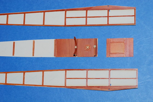
Initially, an attempt was made to build up the fuselage as a frame which would later be covered.
This was not satisfactory. The Fuelage sides were being built up on top of the plans, and as soon as the pins positioning every thing were removed, the frame sprung out of alignment.
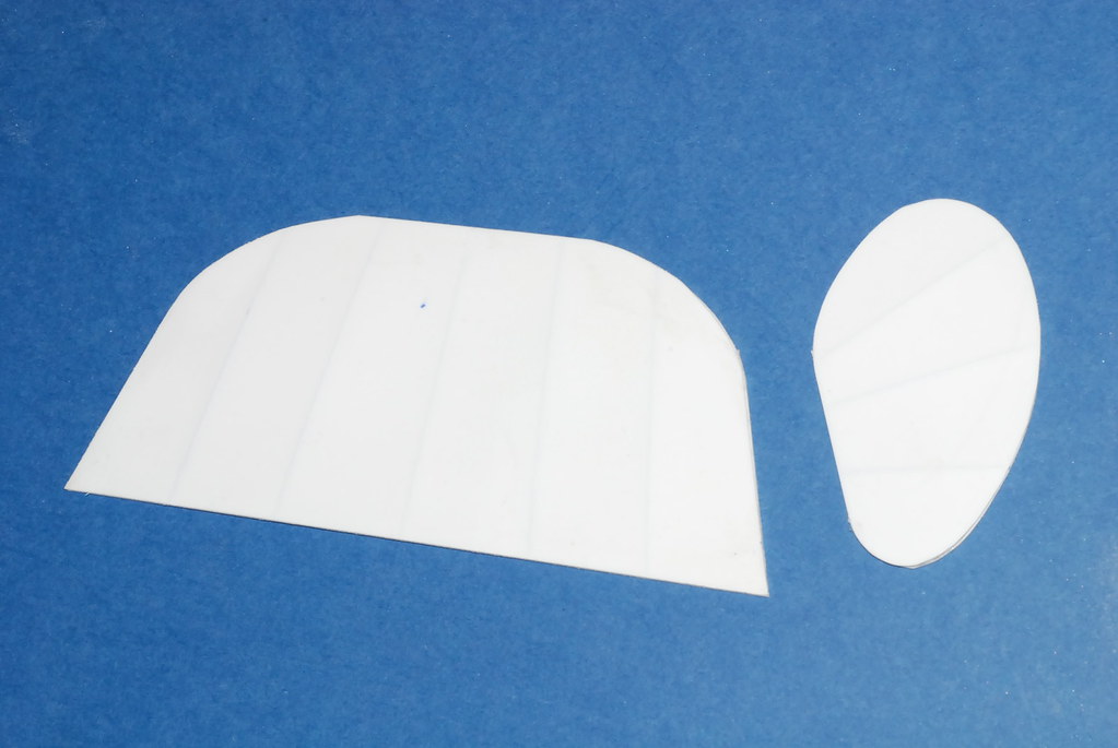
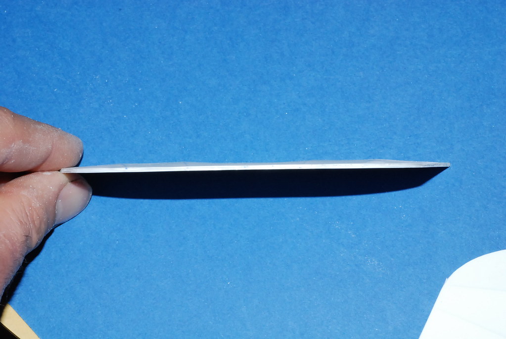
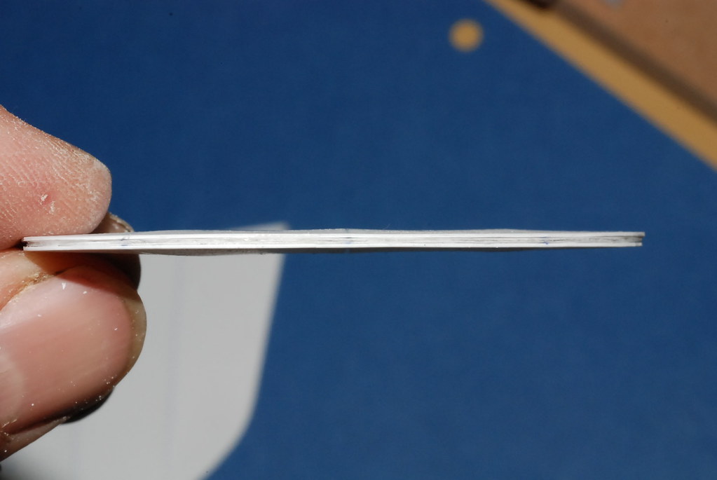
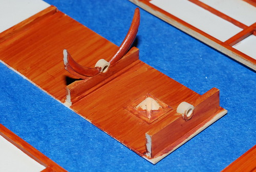
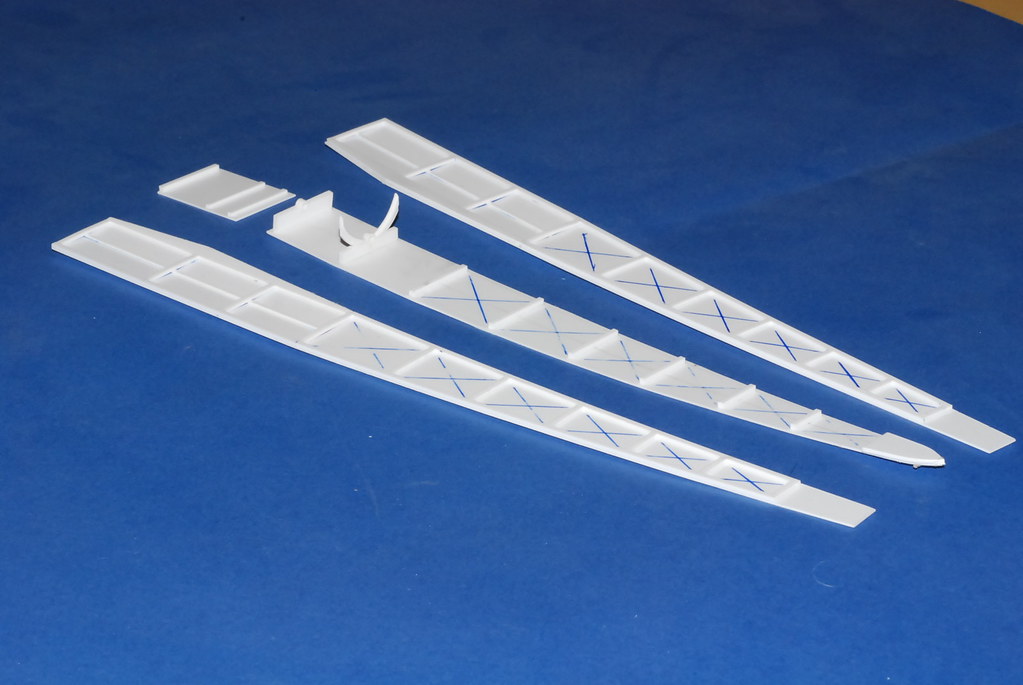
So it was decided that the Framing would be built up seperately as sides and bottom, on top ot the skinning itself already trimmed to the required shape. This was far more successful.
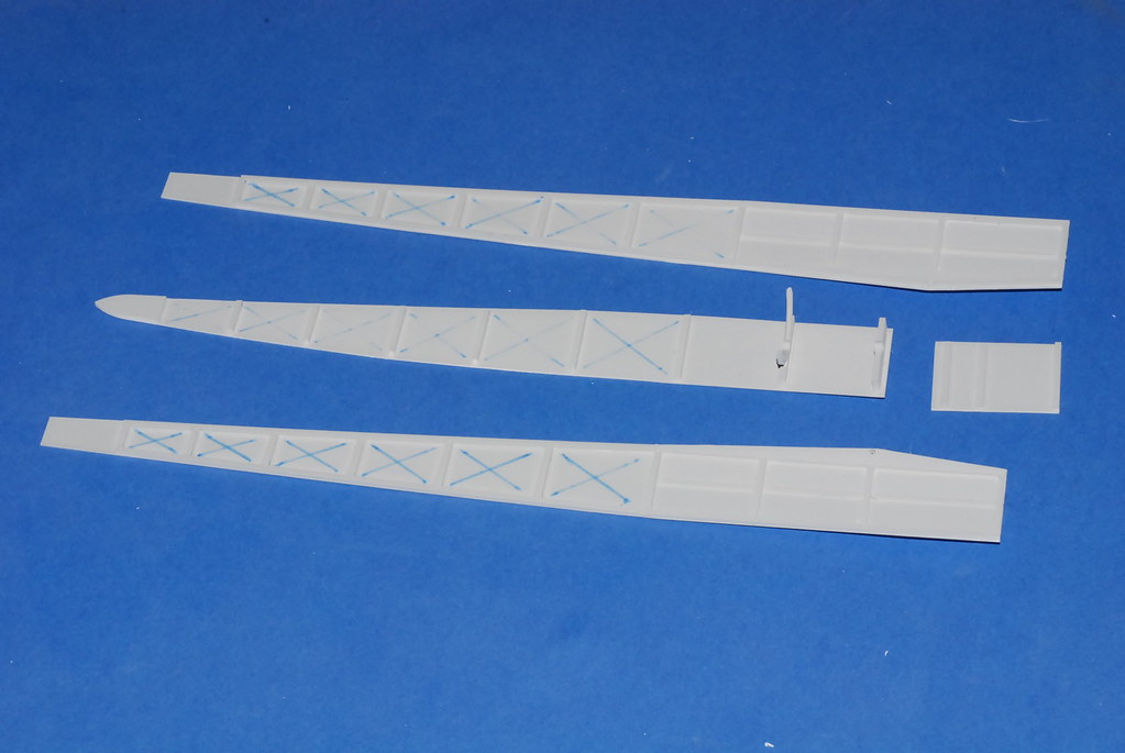
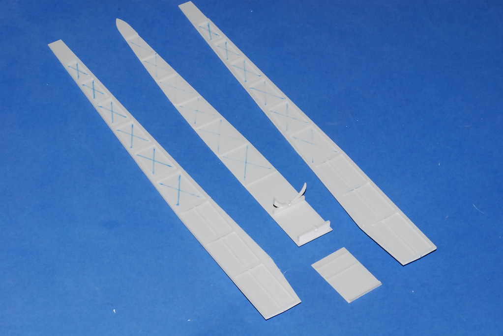
You can see where I have used the simple tool of a ball point pen to emboss the wear and witness marks that would be left by the loose fabric flapping against the bracing wires. The wires themselves will be added after painting.
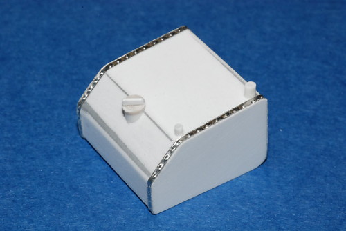
And after a coat of Primer.
More soon.
Cheers,
Hugh