_GOTOBOTTOM
World War II: Germany
Aircraft of Germany in WWII.
Hosted by Rowan Baylis
BF110 C by Dragon
bill_c
Staff MemberCampaigns Administrator
MODEL SHIPWRIGHTS
_VISITCOMMUNITY
New Jersey, United States
Joined: January 09, 2008
KitMaker: 10,553 posts
AeroScale: 1,198 posts
Posted: Sunday, June 07, 2009 - 10:40 AM UTC


I have long been interested in ths BF-110 airframe, and have reviewed the Nightfighter version here. Years ago I was fascinated by the Wespe ("wasp") nose art of this particular vehicle serving on the Eastern Front, so when I received the Dragon kit of the 110 C for my birthday, I made it a top priority.

The kit is superb.

It does have its faults, including Dragon's notorious garbled instructions. I strongly recommend downloading the errate here, which covers most (but not all) of the problems. But after having struggled with the Revell kit (including enough AM conversions and upgrades to put their original $25 pricetag beyond the $70-$90 the Dragon kit sells for), I decided to build it more or less OOB.

The kit begins logically enough with the cockpit sub-assembly.


While Eduard has some extensive PE for this kit, as I said, I decided to build it more or less OOB, other than correcting its seatbelts (on order from GreatModels.com). Additionally the decals are beautifully-done-- Dragon's usual excellent outsourcing from Cartograf-- but woefully incomplete: no tail swastikas nor any of the extensive stenciling on the exterior. With a kit this big, you can't leave out the stencils, so I added the EagleCals set for this particular plane.

The BF110 started life as an escort fighter, but it soon became apparent during the Battle of Britain that it was both too slow and insufficiently maneuverable to compete with single-seat pursuit planes, especially the Spitfire. The C is the fighter-bomber version used to drop bombs and strafe ground targets, and was armed with four nose-mounted machine guns and two internally-mounted 2cm cannon in the belly (there is also a gunner-operated single MG at the rear of the cabin).
bill_c
Staff MemberCampaigns Administrator
MODEL SHIPWRIGHTS
_VISITCOMMUNITY
New Jersey, United States
Joined: January 09, 2008
KitMaker: 10,553 posts
AeroScale: 1,198 posts
Posted: Tuesday, June 09, 2009 - 05:46 AM UTC
The canopy of the BF110 has some extensive electronics in it, especially the later nightfighter versions. This variant deals with that using a frame above the radio operator’s post:


The sheer amount of glass made me cry “uncle” and resort to Eduard’s mask set. Montez has a double mask for both the inside and outside:


Armaments


The main bomb rack:


The wing bomb racks:


Wolfpack
_VISITCOMMUNITY
England - North, United Kingdom
Joined: April 10, 2005
KitMaker: 78 posts
AeroScale: 43 posts
Posted: Tuesday, June 09, 2009 - 06:37 AM UTC
Bill

Whatever you do, don't look at the Bf110 builds on the LSP forum. They'll make you want to cry.

When I built mine, that was also to be an OOB model, but the Dragon kit is a real curates egg, it's just not sure what it wants to be. I ended up building an early 'E' from the kit and spent an age detailing all those areas, including chopping the nose in half.

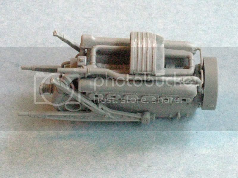
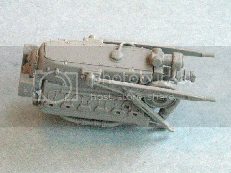
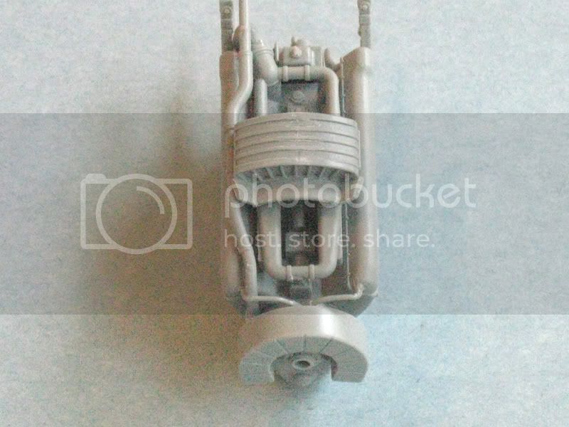
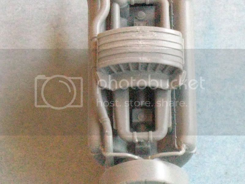
Watch out for the engines, they won't fit properly without work.

Here's a list of items that Dragon left out of the instructions:

Instruction sheet errors and omissions:-
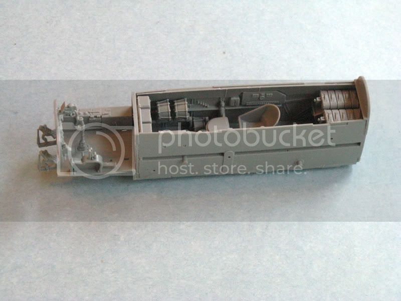
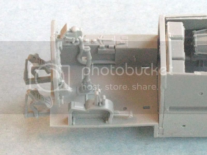
Step 1:
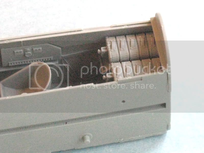
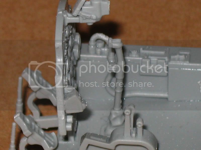
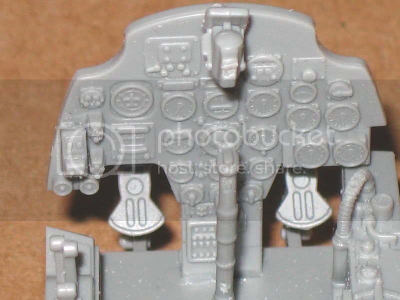
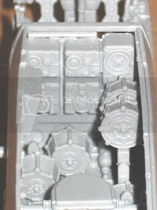
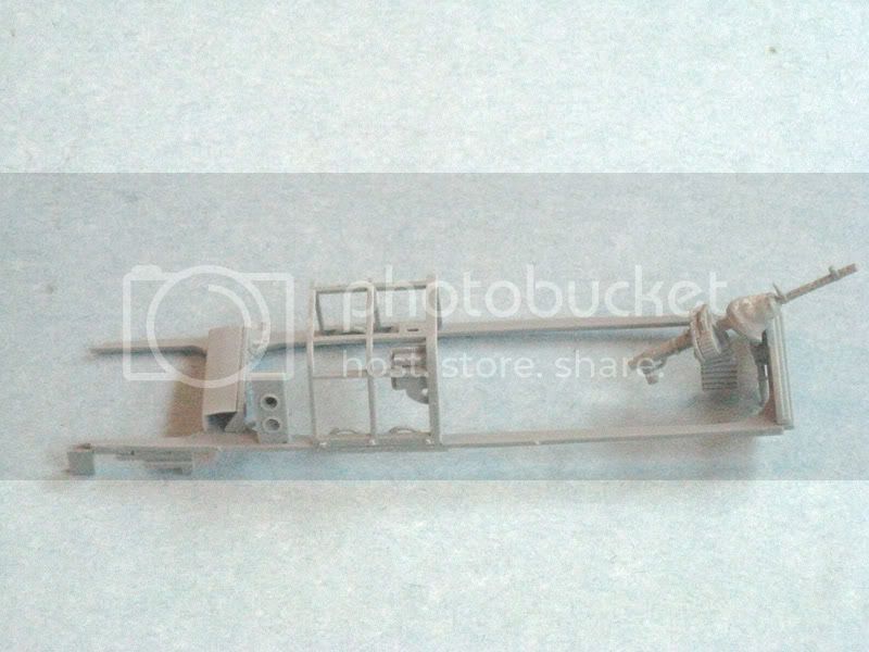
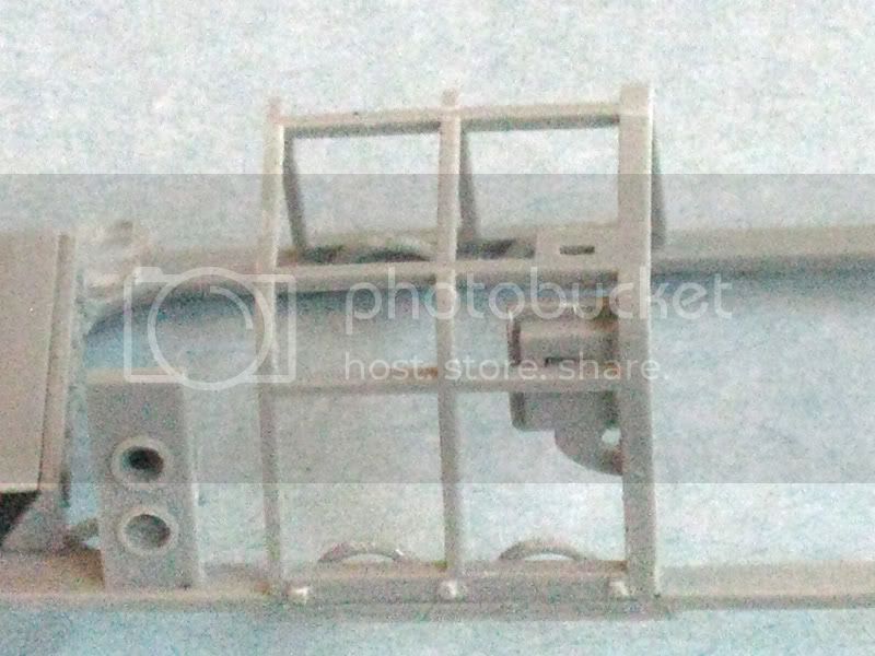
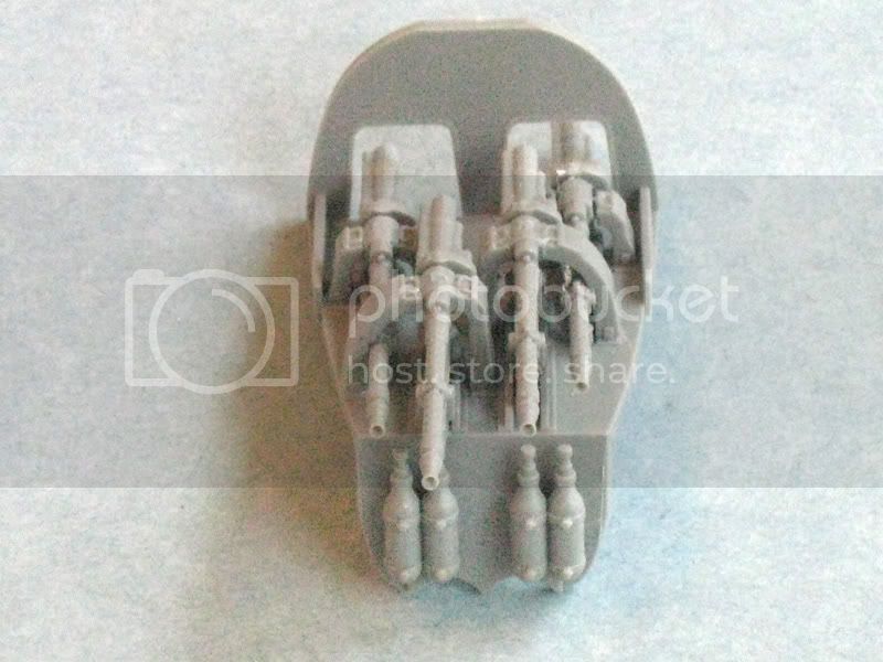
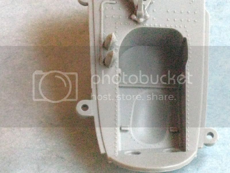
The ventral weapons cradle, E19, and E22, which are shown to be assembled beforehand with D20. Don't do it that way! Cement E22 to the cockpit floor, along with E8, which the radio equipment panel, E9, attaches to. The ventral weapons cradle E19 should slide in from underneath. D20 should be glued to the cockpit floor in the recess on E14. Also there is a second part D20 not mentioned in the instructions. Two extra ammo drums (each made up from parts D55 and D58) should be installed in in the racks. This is not mentioned in the instructions.
E11 needs to be thinned quite a bit at the rear face for E8 to fit against it and the cockpit floor E14 squarely. Also on the front side of E8, the bolt head details for the diagonal stays interferes slightly with the above mentioned fitment.
The pilot’s throttle quadrant is incorrectly labeled part E46 on the instructions. It is actually part D46 on the sprues.
Step 2:
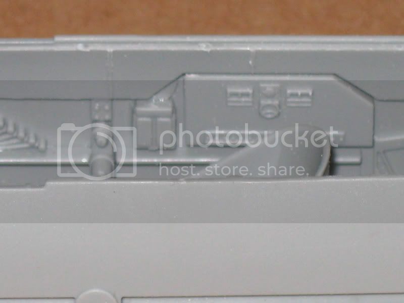
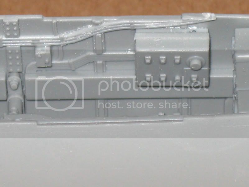
Part E3 is a long fairing that should be installed at the top of part E13, the starboard sidewall. This is not mentioned in the instructions.
Part E1 is a small box that should be installed on the port sidewall. The part is pictured as installed, but not mentioned in the instructions.
Step 3:
Part D59 is the trim wheel. This should be installed on the upper port side of the pilot’s cockpit. This part is not mentioned in the instructions.
Step 5:
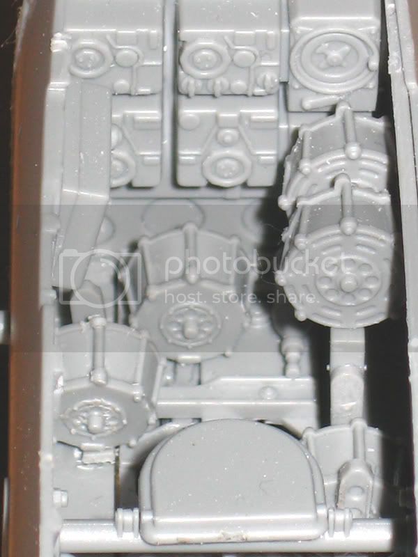
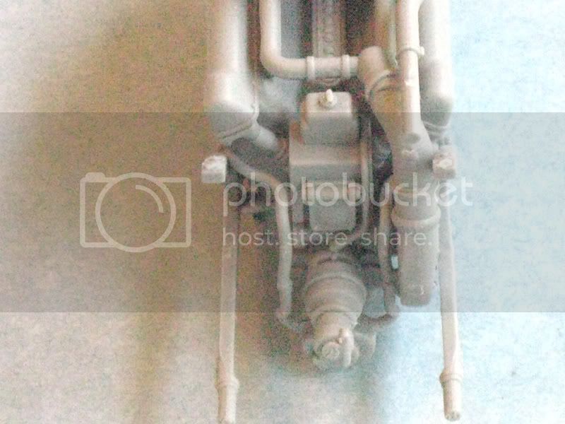
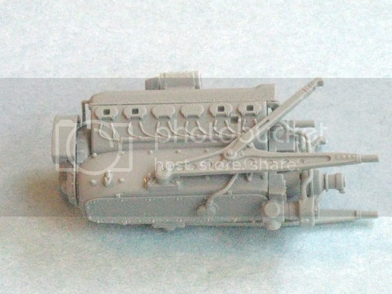
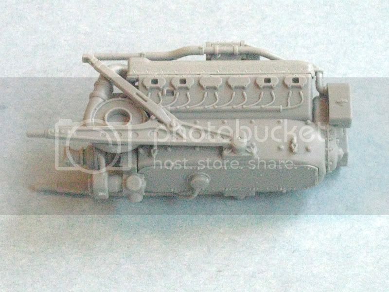
The engine rocker covers (parts J23 and J24) should only be installed after the rear engine parts, as these fit over locating tabs moulded onto part J27.
Parts H16 are engine instruments. These are not mentioned in the instructions. Part H16 should be installed on the inboard engine mount for each engine (parts J17 and J18). These will need to line up with the three small holes in the side of the engine covers.

Step 6:
The illustration of the exhaust panel seems to show the parts back the front. Check carefully before assembly.
I would recommend leaving the installation of the exhausts until the rest of the model has been assembled. There does not appear to be any way to secure the exhausts to the exhaust fairings.
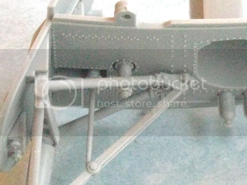
The rear wheel well arch supports (parts A5 and A6) should not be attached to the wheel well ceilings (part N12 and N13) as illustrated. There is no locating position on the wheel well ceilings for these arches. However, there is a positive locating groove inside the rear of the nacelles. The arches should be glued into these grooves.
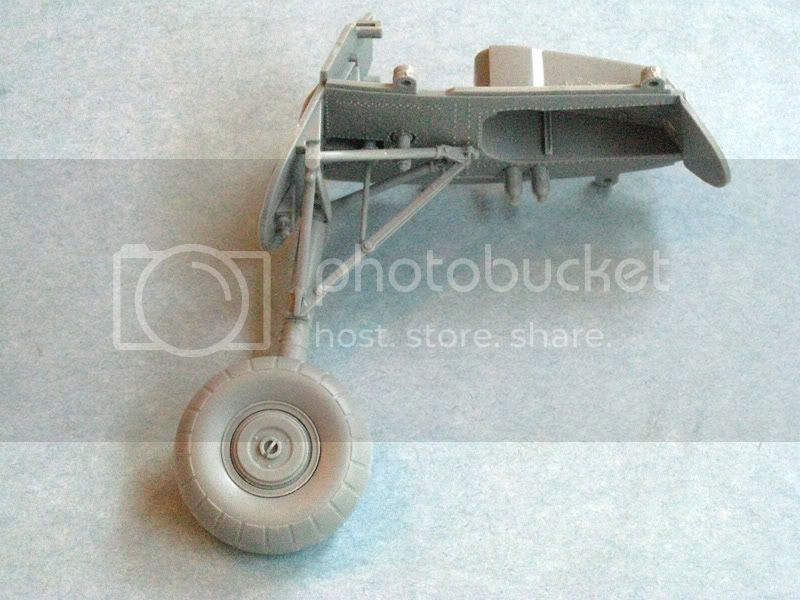
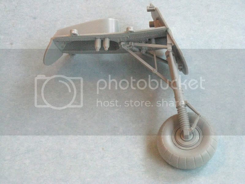
Double-check the front firewall for the wheel wells (parts F34 and F35). These may be incorrectly labeled on the instructions. If the wrong combination is fitted, the wheel well and engine assembly will not fit inside the engine nacelle properly. I had the wrong bulkheads installed and did not find out until attempting to install the wheel wells. I had to remove and swap the bulkheads (this might have been my mistake, but check carefully and test fit anyway)
Parts F15 and F16, the main gear door actuators, should be glued to the gear legs (parts F17 and F18) in Step 6, not in Step 8.
Step 8:
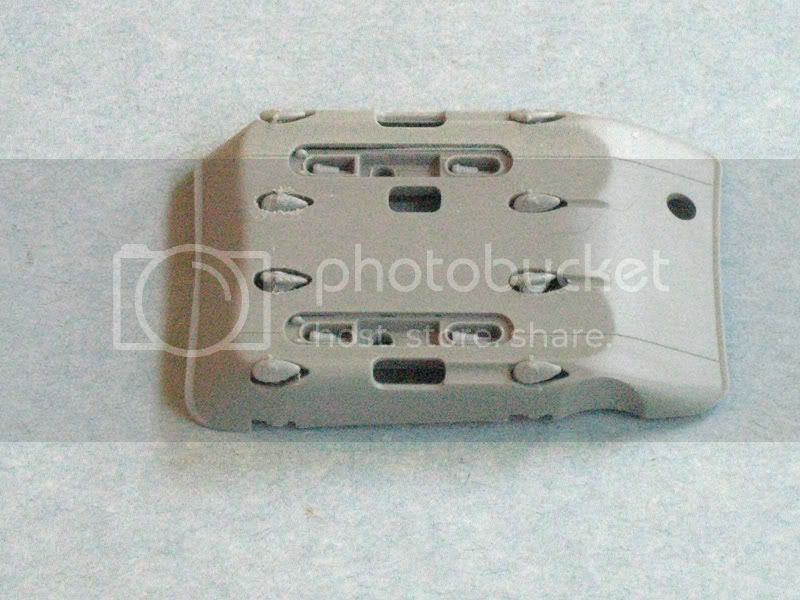
To show the gear bay's internal bulkheads/formers. The way to figure out the left gear bay is, once the right wing's bay is done, match up the relevant parts for the left, bearing in mind the bays are mirror image to each other.
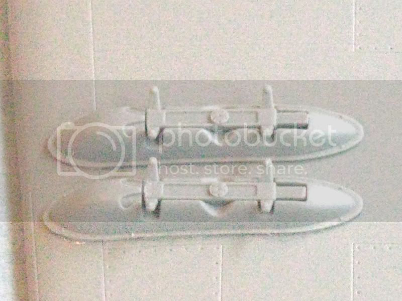
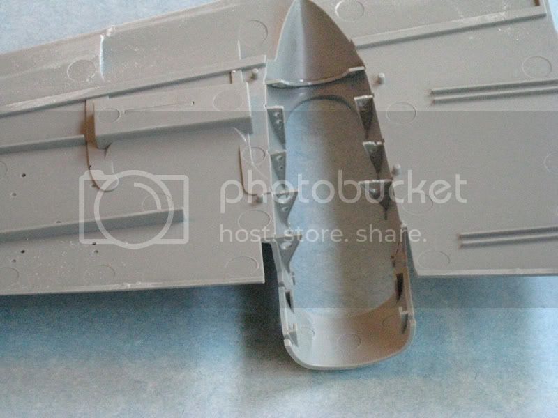
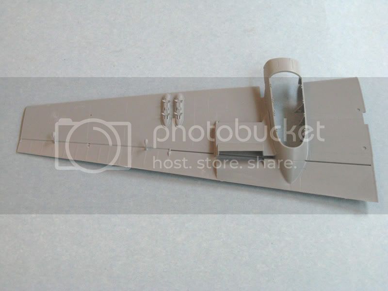
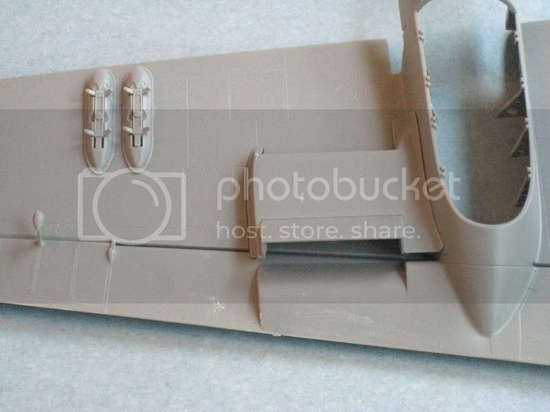
The radiator faces (parts C2, C3, C4 and C5) are pictured with the faces pointing inboard (i.e. toward each other). The grille detail should actually be facing outward. They also appear to be pictured upside down. These parts should actually be fitted into recesses in the bottom of the wings. The locating slots make their positioning quite clear.
Parts N5 are small braces for the radiator. These are not mentioned in the instructions. The braces should be installed near the front opening of the radiators.
Step 11:
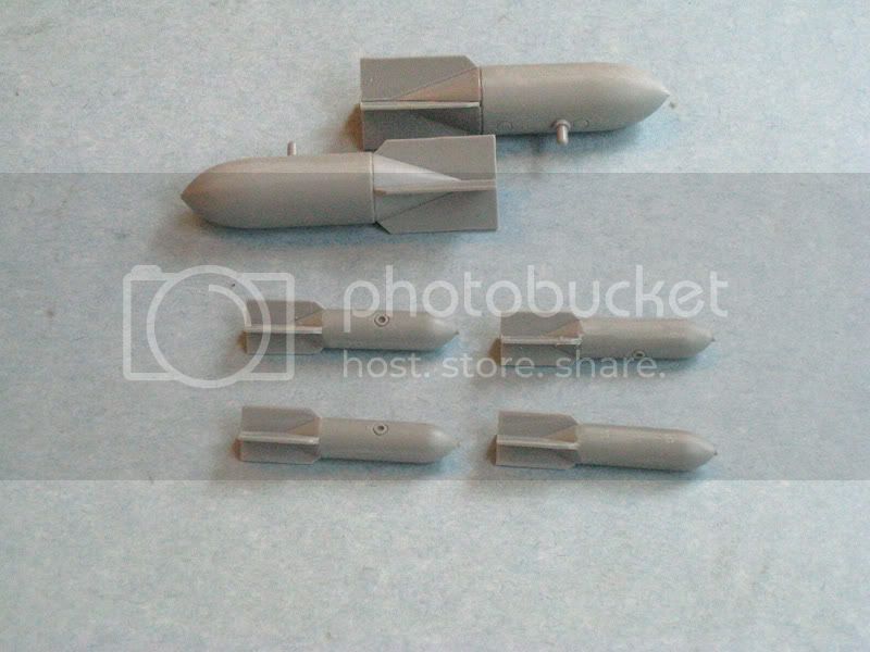
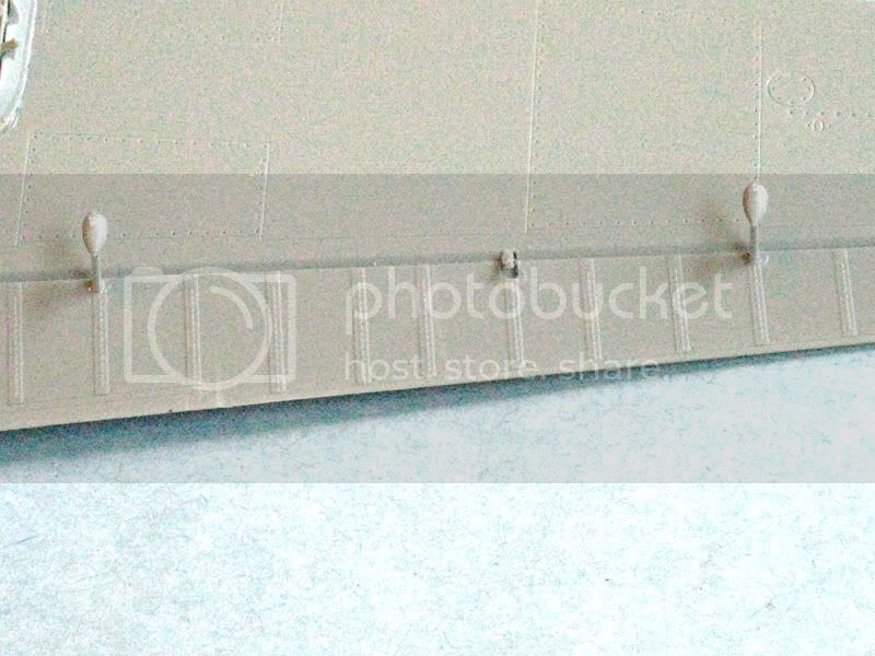
Part N29 is the pitot tube for the later Bf 110 E. Do not open the locating hole or install this part. The correct part for the Bf 110 C and D is the “T” shaped pitot tube, part N8. This part is pictured installed in Step 11, but it is not mentioned in the instructions. The locating hole for this part is already open in the bottom of the starboard wing.

Anyhow, it didn't turn out too bad...............

A special thanks to Holdfast for the code masks. They were spot on.


IAN
bill_c
Staff MemberCampaigns Administrator
MODEL SHIPWRIGHTS
_VISITCOMMUNITY
New Jersey, United States
Joined: January 09, 2008
KitMaker: 10,553 posts
AeroScale: 1,198 posts
Posted: Tuesday, June 09, 2009 - 10:36 AM UTC
Thanks, Ian, I will print that up. I was already using this errata. I know DML doesn't want us complaining about their directions, but I've found problems that weren't in the errata I was using.

Great-looking plane. I intend to build the Wasp version. What are the "code masks by Holdfast"?
Wolfpack
_VISITCOMMUNITY
England - North, United Kingdom
Joined: April 10, 2005
KitMaker: 78 posts
AeroScale: 43 posts
Posted: Tuesday, June 09, 2009 - 08:13 PM UTC
Bill

Holdfast (Mal Mayfield) has desogned and created 'Miracle Masks'. He made the S9+GK masks which I used for the model.

I know he was in the process of creating a mask for the Wasp, why not e-mail him at [email protected] and see how far he's got?

You might also want to consider buying this, I did and it helped tremendously.


Best of luck with this and remember, Dragon is Chinese for "It doesn't Fit."


IAN
bill_c
Staff MemberCampaigns Administrator
MODEL SHIPWRIGHTS
_VISITCOMMUNITY
New Jersey, United States
Joined: January 09, 2008
KitMaker: 10,553 posts
AeroScale: 1,198 posts
Posted: Wednesday, June 10, 2009 - 10:21 AM UTC
Thanks, Ian, I'll check all that out!

Bill
bill_c
Staff MemberCampaigns Administrator
MODEL SHIPWRIGHTS
_VISITCOMMUNITY
New Jersey, United States
Joined: January 09, 2008
KitMaker: 10,553 posts
AeroScale: 1,198 posts
Posted: Thursday, June 11, 2009 - 05:51 AM UTC
The BF110 engines were mounted upside down, and the level of detail in this kit is just wonderful:


Not all is perfect in the kit: these air intake manifolds need extensive clean-up, so much so I’m not sure they can be fully “fixed”:


I know I should sand off and drill out the spark plugs and wires, but I don't plan on having the nacelles open. As I stated up-front, I'm more interested in building this one for pleasure.

Now, if Dragon is planning on extending this kit to the G variant, I might go whole hog next time!
bill_c
Staff MemberCampaigns Administrator
MODEL SHIPWRIGHTS
_VISITCOMMUNITY
New Jersey, United States
Joined: January 09, 2008
KitMaker: 10,553 posts
AeroScale: 1,198 posts
Posted: Friday, June 12, 2009 - 04:20 AM UTC
After the incorrect or non-existent detailing for the wheel wells on the RoG kit, the level of styrene excellence here is an eye-opener:


The landing gear:


The wheels do not spin, an annoying oversight by Dragon, since making the wheel inner hubs slightly longer would allow for that option (which makes painting easier). I put a little extra PE inside to allow the wheels to spin.

The RoG kit requires both an interior upgrade for the instruments and radar gear, as well as an exterior one for the air intakes. Not so for the Dragon kit:


Detailing on the control surfaces is excellent, too:


 _GOTOTOP