
The engines I am working on are Wright R-1820 9 cylinder Cyclones. They have one ignition wire entering the front of the cylinder, and one going into the top.
 (From Wikipedia)
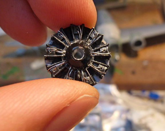
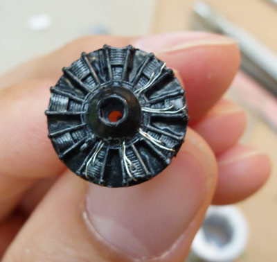
This MPM engine is not particularly nice to look at, so I though I would try and make it look a bit more 'busy', and less like an obviously moulded piece of plastic.
The obvious way to attach wires would be to drill a fairly shallow holes at the start and end points, and try to glue one end of a piece of wire into a hole. This is quite tricky, as superglue doesn't like gripping thin wire, so you really have to wait until the glue is dry. then it is hard to manipulate the short length of wire into a small hole, and to have the length right so it doesn't reach the bottom of the hole. As I have no suitable tweasers, this job was driving me crazy.
So I developed an easier way:
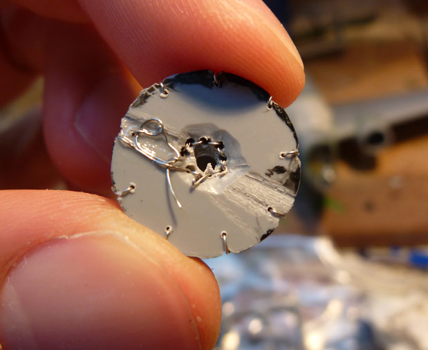
1) Drill out the centre of the engine- we need a large hole running straight through. Don't use a larger drill than the diameter of the prop's axel stub, else it will be a pain to attach and align later.
2) Using the smallest drill bit available, start from the front of the cylinder, and drill about half way into it, angling slightly towards the top of the cylinder.
3) drill from the top of the cylinder to meet the first hole (angling slightly towards the front of the cylinder).
These angles make threading the wire easier.
3) Using a larger drill bit (so two pieces of wire can pass through the same hole fairly easily), drill through the 'hub' at the centre of the cylinders, angling slightly towards the back of the engine. Continue drilling until you come out into the large hole through the engine.
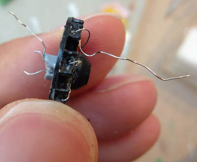
3) Thread a fairly long (too long won't hurt) piece of wire from the top hole through until it comes out the front.
(ignore the two pairs of wires on the left, they were aborted attempts at doing it the obvious, but harder, way)
4) Pull about half of the wire through the hole.
5) continue downwards with this wire, threading it into the hole into the 'hub'.
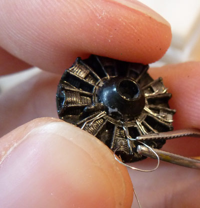
6) using tweezers, push the wire down the hole. If it stops (caused by hitting the wall of the central hole at too steep an angle), poke something down the central hole, from the front, bending the end of the wire to allow it to head out of the rear of the engine.
7) Once it has poked out the back, you can pull quite hard to gt the rest of the wire through.
8) Now repeat from step 3 for the other end of the wire.
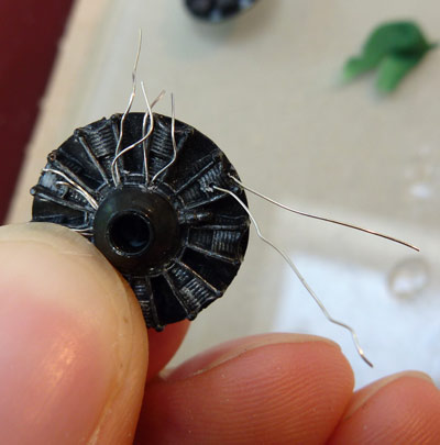
9) Arrange the wires in a realistic way (shortening them by pulling from the rear, lengthen them by levering somethind behind the wires on the front, which pulls some slack through from the back).
10) after all cylinders are wired, you can cut the wires to length at the rear of the engine, and glue them (or not).
The next step will be to make a ring of thicker wire around the hub to represent the distribution system. Apologies for the horrid gloss black paintwork with silver drybrushing- I will hopefully re-work the paint job into something more passable.
The advantages of this method:
Quicker and much easier.
No super glue so: no problems of it coming unstuck when you are threading the opposite end of the wire, no mess left on the fine detail of the cylinders.
Cutting the correct length of wire is no longer important.