_GOTOBOTTOM
Cold War (1950-1974)
Discuss the aircraft modeling subjects during the Cold War period.
Hosted by Tim Hatton
Kinetic 1/48 Mirage IIIE
litespeed
Staff MemberNews Reporter
AEROSCALE
_VISITCOMMUNITY
England - North West, United Kingdom
Joined: October 15, 2009
KitMaker: 1,976 posts
AeroScale: 1,789 posts
Posted: Saturday, April 04, 2015 - 01:08 AM UTC


Hi all

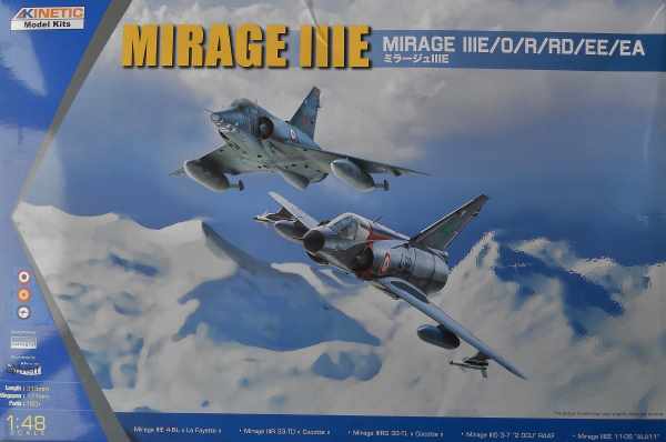
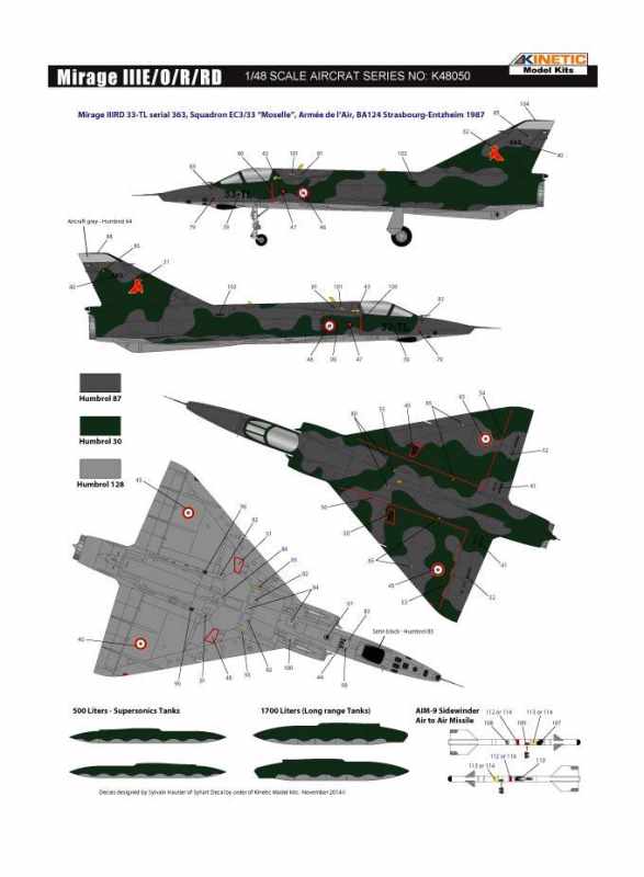
Having reviewed the Kinetic 1/48 scale kit of the Mirage IIIE recently, I decided it was going to go to the top of my must build list. You can find my review here. I have always been interested in photo reconnaissance aircraft, so I was pleased to see a “recce” Mirage III R/RD option included with this release. In actual fact markings are shown in the painting guide for Mirage IIIR, but there is no scheme for the IIIRD. Even odder is that there are marking included on the decal sheet for an IIIRD. The Kinetic facebook page has an explanation for the omission; they just forgot to add the scheme in the instructions. Anyway they have published the missing scheme on their facebook page and I have included it below.


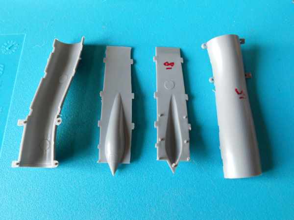
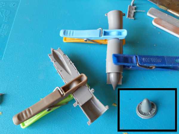
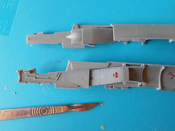
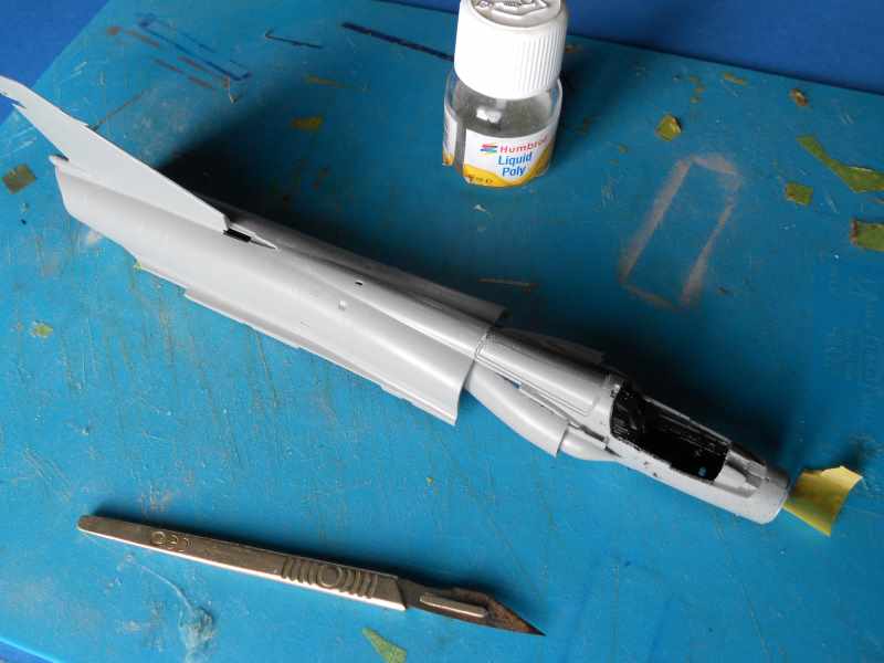
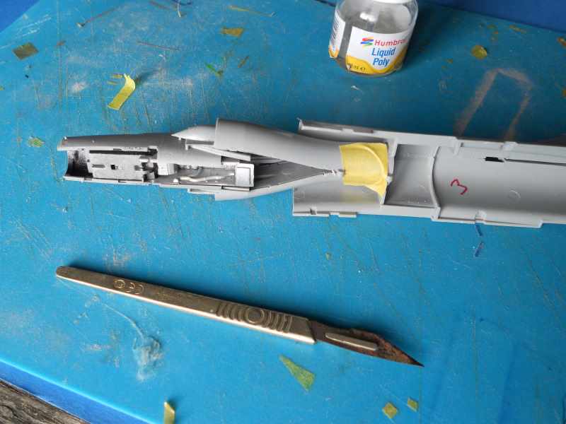
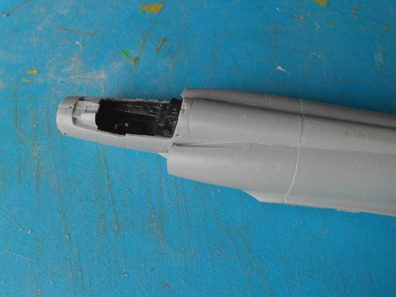
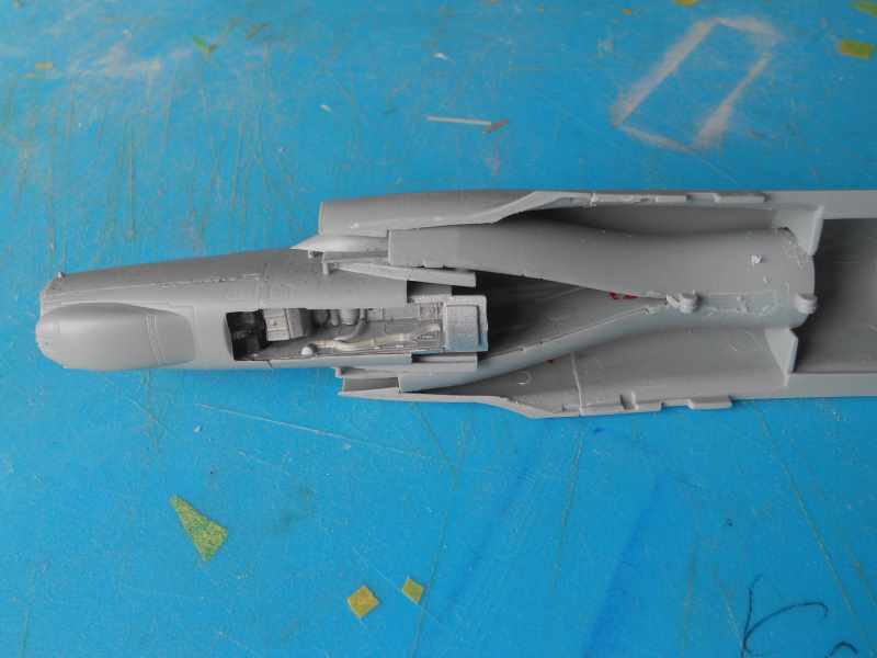
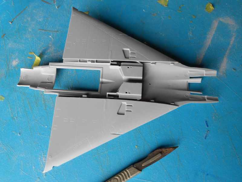
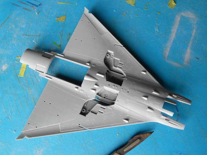
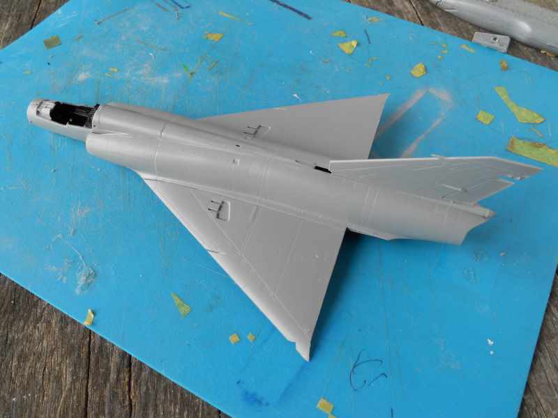
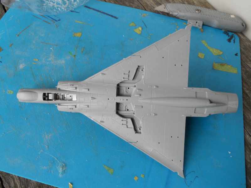
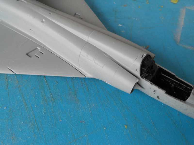
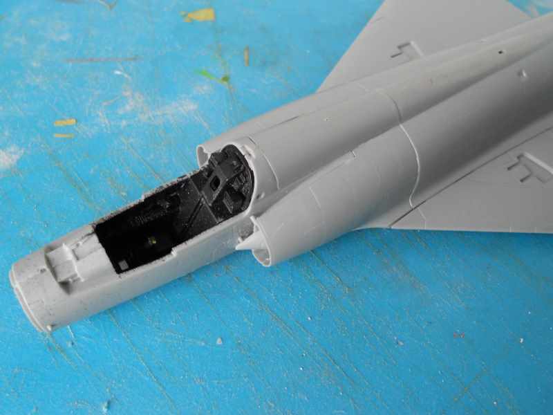
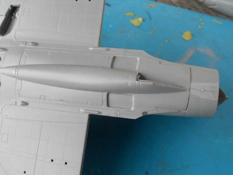
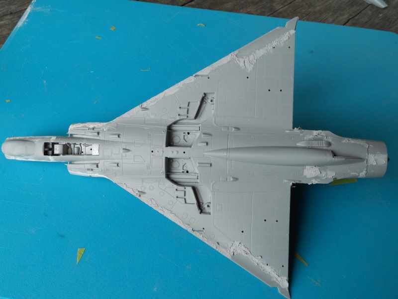
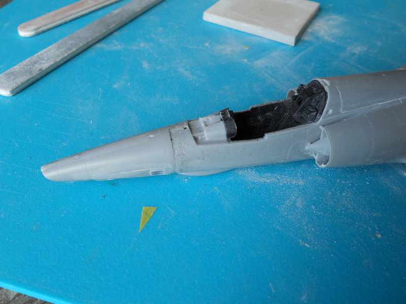
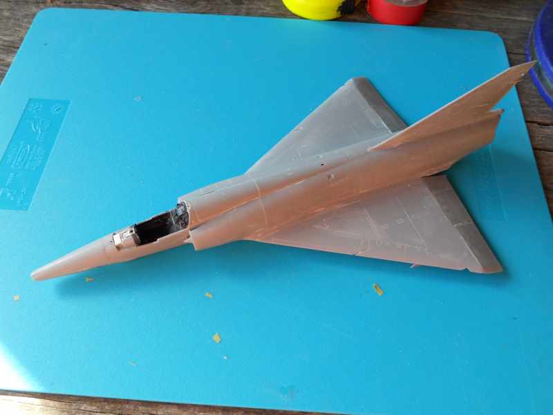
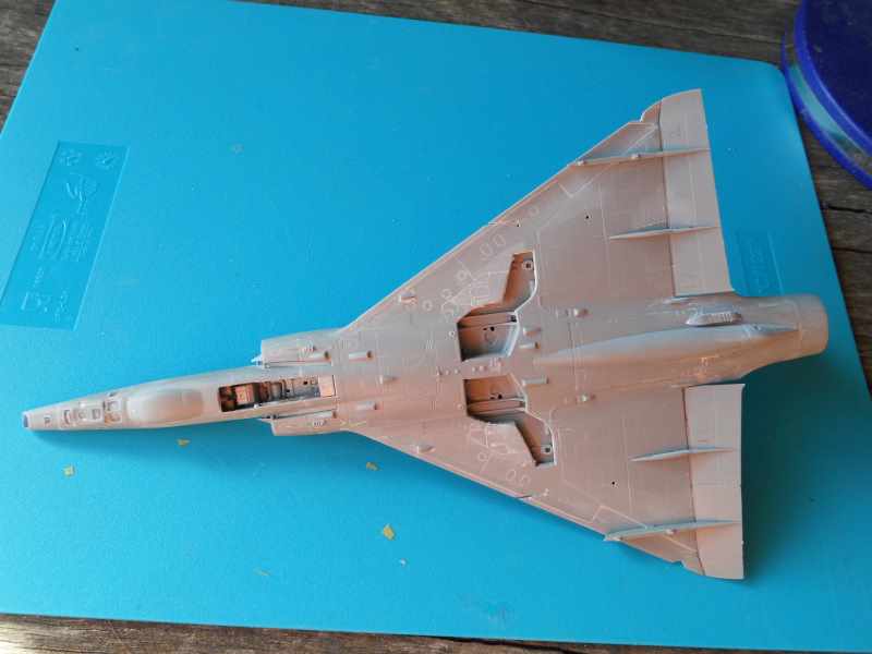
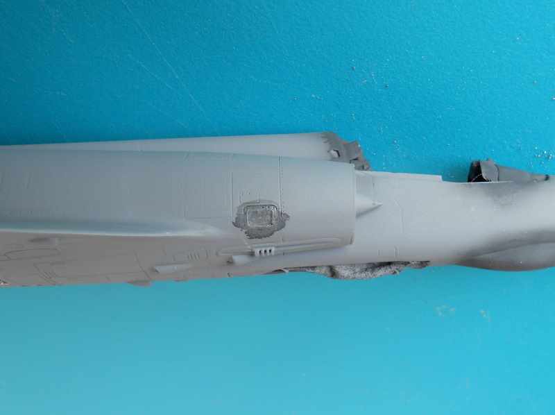
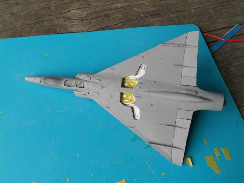
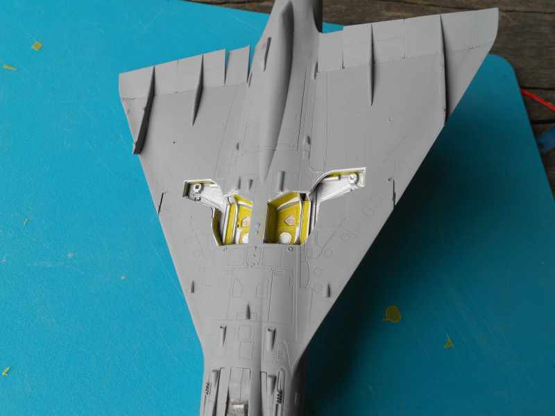
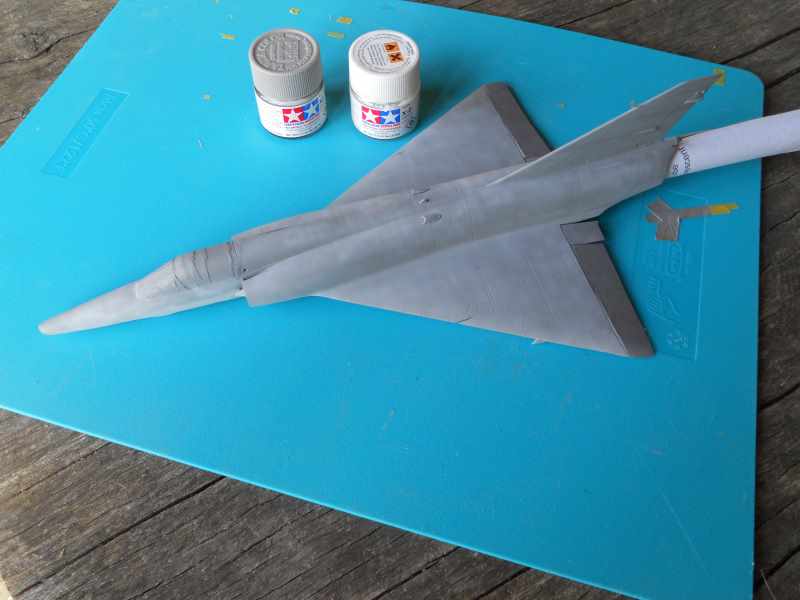
Right onto the build. The first thing I did was join the parts creating the air duct. There are two raised ejector marks on the inside of each duct, but I doubt you will see them once the parts are joined. I will leave them on just to see. I like where the joins are located and there should be little evidence of them once the parts are glued together. The ducts are a little tricky to install into the fuselage. I was glad I numbered the parts as I wondered at one point if I had the parts mixed up. Once in the correct position they seem to click into place. There is a compressor fan to add at the end of the duct, but I suspect you will not see it once everything is buttoned up.

To be continued…….


JPTRR
Staff MemberManaging Editor
RAILROAD MODELING
#051
_VISITCOMMUNITY
Tennessee, United States
Joined: December 21, 2002
KitMaker: 7,772 posts
AeroScale: 3,175 posts
Posted: Saturday, April 04, 2015 - 01:36 AM UTC
Hi Tim,

I'll be watching.

Those plastic clothespins, do they ever scratch the model?
litespeed
Staff MemberNews Reporter
AEROSCALE
_VISITCOMMUNITY
England - North West, United Kingdom
Joined: October 15, 2009
KitMaker: 1,976 posts
AeroScale: 1,789 posts
Posted: Saturday, April 04, 2015 - 01:47 AM UTC
Hi Fred

Welcome to this build log. Good question concerning the clothes pegs. I have not seen any evidence of them scratching the surface. I tend to use them on thinner parts such as wings and stabilisers. They don't open far enough for the slightly wider things like the fuselage, engine nacelles, etc.

tim
Joel_W
Staff MemberAssociate Editor
AUTOMODELER
_VISITCOMMUNITY
New York, United States
Joined: December 04, 2010
KitMaker: 11,666 posts
AeroScale: 7,410 posts
Posted: Sunday, April 05, 2015 - 07:21 PM UTC
Tim,
I'll also be following right along after having really enjoyed your last build.

I do find it somewhat weird that Kinetic forgot to include a complete paint scheme. One really has to wonder if any of these newer companies have anyone checking the final production boxing before it actually goes into production.

Joel
litespeed
Staff MemberNews Reporter
AEROSCALE
_VISITCOMMUNITY
England - North West, United Kingdom
Joined: October 15, 2009
KitMaker: 1,976 posts
AeroScale: 1,789 posts
Posted: Monday, April 06, 2015 - 01:34 AM UTC

Quoted Text


I do find it somewhat weird that Kinetic forgot to include a complete paint scheme. One really has to wonder if any of these newer companies have anyone checking the final production boxing before it actually goes into production.

Joel


Yes it is weird Joel, but unfortunately not unusual with companies from SE Asia. I don't think the various departments or sub contractors talk to each other. There certainly does not seem to be anyone checking the product before it hits the shops. Normally it's not a problem for experienced modelers, but if you are new to the hobby it can be very perplexing and at worst put you off modeling for long time.
To be fair to Kinetic though, they have an active facebook page that keeps you up to date with any changes.

right back to the build.

The cockpit is made up from quite a few parts and looks good once built up. The raised detail is fine, but does disappear in parts. As with most combat aircraft of this era, the inside of the cockpit is mostly black in colour. Some of the switches and instruments were highlighted with some colour. I used reference images from the internet as there are no details in the instructions. The hardest parts to install were the rudder pedals. Boy the air was blue after umpteen tries to get them looking right with some tweezers! I ended up using a cocktail stick with a tiny blob of blue tack on the end and the rudder pedals went into their positions first time. The seat will be built later.

To be continued…….


litespeed
Staff MemberNews Reporter
AEROSCALE
_VISITCOMMUNITY
England - North West, United Kingdom
Joined: October 15, 2009
KitMaker: 1,976 posts
AeroScale: 1,789 posts
Posted: Thursday, April 09, 2015 - 01:21 AM UTC
Hi all

The cockpit and the forward undercarriage bay were installed with little fuss. I will be the fitting the seat later in the build. The fuselage halves were joined but some work was needed on the mating surfaces of the fuselage as the join was not very good. There were a few gaps that just would not close up. So a few swipes with a sanding stick soon put things right.

Also the design of the fuselage makes it difficult to clamp the halves together. I ended up using small spots of super glue along the spine and held the two halves together while the glue set. Then I reinforced the join with liquid glue.

To be continued…..


litespeed
Staff MemberNews Reporter
AEROSCALE
_VISITCOMMUNITY
England - North West, United Kingdom
Joined: October 15, 2009
KitMaker: 1,976 posts
AeroScale: 1,789 posts
Posted: Friday, April 10, 2015 - 01:55 AM UTC
Hi all

Part of the air intake and the spine behind the cockpit has been added. The joins are reasonable, but they certainly do not look like a panel lines. They will need some filling, a bit of sanding and blending. I also added the distinctive Doppler radar housing under the nose. Again the join is less than perfect. You can see the detail in front undercarriage bay is pretty good. I did pick out some of the detail with various shades of grey and aluminium, but it’s not obvious from this photo.Images in this area on the real thing generally show a lack of variation in colour. The main undercarriage bay on the other hand should look a bit more interesting though when I get around to it.

To be continued......


Joel_W
Staff MemberAssociate Editor
AUTOMODELER
_VISITCOMMUNITY
New York, United States
Joined: December 04, 2010
KitMaker: 11,666 posts
AeroScale: 7,410 posts
Posted: Monday, April 13, 2015 - 12:40 AM UTC
Tim,
The cockpit from what I can see looks pretty good. But those glue joints look like a lot of work.
Joel
litespeed
Staff MemberNews Reporter
AEROSCALE
_VISITCOMMUNITY
England - North West, United Kingdom
Joined: October 15, 2009
KitMaker: 1,976 posts
AeroScale: 1,789 posts
Posted: Monday, April 13, 2015 - 02:23 AM UTC

Quoted Text

Tim,
The cockpit from what I can see looks pretty good. But those glue joints look like a lot of work.
Joel


There is one thing you have to expect from Kinetic aircraft kits Joel and that is sooner or later during the build there will be some work on the joints. Kinetic like many companies out there are trying to wring out as much use from the moulds as possible, so the kits become modular, which can mean more work for the modeler. I have tried to be very careful with the joins, but the joins look more akin to welded tank plates! Hopefully I will be able to clean them up. I do laugh at some of the model companies claims that the joins fall on the panel lines on the actual aircraft. Yes they might, but the joins rarely look like the finely recessed panel lines on modern kits.

In short I do like building Kinetic kits as they certainly are not shake and bake kits and I do like testing my building skills with them.

The wings were built, but I did have problems with the locating pins. They seemed to be very slightly misaligned. So I cut a couple of the locating pins off and the wings fitted together fine.


I attached the wings to the fuselage, but boy was it a struggle. The problem is trying to squeeze together the part of the intake on the wing to the intake on the fuselage. I tried clamping, taping and elastic bands, but no joy. In the end I resorted to applying spots of super glue and holding the parts in place till the glue set. I reinforced the join with some liquid glue.


There is a sizable gap to fill along the fuselage/wing join. Hopefully this will be easily done with some stretched sprue. The rear end of the fuselage attached to the lower wing needed a small amount of plastic removing with a sanding stick. One part that does fit very well is the fuel tank underneath the rear fuselage.


To be continued…….
Joel_W
Staff MemberAssociate Editor
AUTOMODELER
_VISITCOMMUNITY
New York, United States
Joined: December 04, 2010
KitMaker: 11,666 posts
AeroScale: 7,410 posts
Posted: Tuesday, April 14, 2015 - 10:53 PM UTC
Tim,
I'm really enjoying your "war" with the kit, and how you end up winning each "battle". I'm always concerned when I have to squeeze fit parts together that down the road the expansion will pop the parts. I usually do anything necessary to make the parts more of a drop in type fit.
Joel
litespeed
Staff MemberNews Reporter
AEROSCALE
_VISITCOMMUNITY
England - North West, United Kingdom
Joined: October 15, 2009
KitMaker: 1,976 posts
AeroScale: 1,789 posts
Posted: Wednesday, April 15, 2015 - 02:38 AM UTC

Quoted Text

Tim,
I'm always concerned when I have to squeeze fit parts together that down the road the expansion will pop the parts. I usually do anything necessary to make the parts more of a drop in type fit.
Joel


Yes Joel, the sound of a seam popping open just after you have applied that last stencil is a thing of nightmares.

The fit of the single clear plastic which represents the windows for the cameras is not great. Some filler and cleaning up will be necessary. The instructions do not mention the transparent covers for the camera [A] in the tip of the nose and the camera [B] behind. I scratch built the camera cover [B] using a section of clear sprue which I filed four sides onto. I thought occurred to me that the parts might be included on the clear sprue. Sure enough there they are. So I will use my improvised cover for [B] and use the kit part for [A]. As you can see from the image I have filled the slight gaps around the clear camera cover. I will sand this down later and buff up the clear parts with Micromesh polishing cloths.The marks in the clear parts I think are flaws, but the do give the impression of a camera lens. So I have made no attempt to get rid of them.


I have started filling in all of the obvious seams on this kit. I used stretched sprue on the wing root, Humbrol filler on most of the other joins and super glue and talc on the seam on the air intakes. As Joel pointed out it is always a concern that joins that have been forced into place may spring open later. Isn’t this fun!!!!


Despite the work I am really enjoying this build particularly now the gorgeous lines of the Mirage III are taking shape. I have been comparing the kit to some images and I have to say Kinetic have captured the shape nicely. The shape of the wing with the slight anhedral and the shape around the wing tips and leading edge look very good.


To be continued…..

tim
Joel_W
Staff MemberAssociate Editor
AUTOMODELER
_VISITCOMMUNITY
New York, United States
Joined: December 04, 2010
KitMaker: 11,666 posts
AeroScale: 7,410 posts
Posted: Wednesday, April 15, 2015 - 10:24 PM UTC
Tim,
I had to laugh when I read that after you spent the time to make the clear lenses, you found them on the clean sprue. I've made more then my fair share of scratched out parts, only to find them loose in the box, or in my parts bin simply because I forgot that I had already prepared them for gluing and painting. Us old modelers do have this special challenge from time to time.

I'm really looking forward to seeing your Mirage IIIE with some primer on.

Joel
Thearmorer
_VISITCOMMUNITY
Alabama, United States
Joined: June 17, 2014
KitMaker: 121 posts
AeroScale: 118 posts
Posted: Wednesday, April 15, 2015 - 11:11 PM UTC
Tim,
Good looking and informative build you've got going here. I don't do that many tail-burners myself but I do like to keep my finger on the pulse of what's out there and how it's done. In particular it looks like your filler application techniques are not dissimilar to my own, so I will be taking careful notes on how you shovel your way through this fit challenge, and end up with any surface detail at all. Keep up the good work, I might learn something.

DR
litespeed
Staff MemberNews Reporter
AEROSCALE
_VISITCOMMUNITY
England - North West, United Kingdom
Joined: October 15, 2009
KitMaker: 1,976 posts
AeroScale: 1,789 posts
Posted: Thursday, April 16, 2015 - 01:01 AM UTC
Yes I did not have my thinking hat on Joel!!! I do prefer my solution of representing the glazing on camera port B [see above image]. The kit part is so small and difficult to glue, particularly with my clumsy hands.

I am very careful cleaning up the filled seams DR. I generally protect the detail with decorator’s masking tape before I go to work on the filler. Any lost detail is simply rescribed.

The fit of the nose to the fuselage is not great, so some work is needed to blend the nose into the fuselage. I have started cleaning up the various filled areas. One of the poorest areas for fit of parts is under the rear tail cone. The inserts either side of the fuel tank is poor by any standards.

The application of the filler makes the joints look worse than they really are particularly on the under surfaces of the wing. I tend to use plenty of filler in the eternal hope that all the seams will be flawless on the first pass with the sanding sticks and sponges.


I have fitted the actuator housing and the control surfaces for the wing. No dramas here.

To be continued…..


litespeed
Staff MemberNews Reporter
AEROSCALE
_VISITCOMMUNITY
England - North West, United Kingdom
Joined: October 15, 2009
KitMaker: 1,976 posts
AeroScale: 1,789 posts
Posted: Sunday, April 19, 2015 - 02:26 AM UTC
Hi all

I sprayed a couple of coats of Halford acyrilic primer to see if any seams needed further attention. There are a couple of places including a small area of wing root that require further attention. The main undercarriage bay was painted aluminium. It looks a little bright so I will tone it down later. One thing I did discover was a rectangular hole in the right side of the fuselage. Something is meant to be placed in it, but there are no clues in the instructions. I can’t believe I did not see it before priming. I know the Mirage 2000 has small windows to inspect the air intake, but I cannot find any images showing any such widow on the Mirage III/5. There is a clear plastic part that fits the hole so I have put that in. Any info on this area would be much appreciated.

If you have been following closely you may have noticed I have reset the inboard elevons.


The seat has been built and looks pretty good, but needed some scratch built seat harness. I sprayed a light mist of dark grey over the boxes at the back of the cockpit, as I thought the black I had painted them previously was far too dark.


To be continued……
Joel_W
Staff MemberAssociate Editor
AUTOMODELER
_VISITCOMMUNITY
New York, United States
Joined: December 04, 2010
KitMaker: 11,666 posts
AeroScale: 7,410 posts
Posted: Sunday, April 19, 2015 - 05:45 PM UTC
Tim,
And yes, I didn't notice that you raised the inner most set of Elevons. It does add a little more interest. Nice catch on that window. Once again the QC dept at Kinetic missed it.

Joel
litespeed
Staff MemberNews Reporter
AEROSCALE
_VISITCOMMUNITY
England - North West, United Kingdom
Joined: October 15, 2009
KitMaker: 1,976 posts
AeroScale: 1,789 posts
Posted: Wednesday, April 22, 2015 - 02:19 AM UTC

Quoted Text

Tim,
Nice catch on that window. Once again the QC dept at Kinetic missed it.

Joel


Joel you need to be on your toes building this kit

The wheels were painted before assembly, but as you can see from the image, the two halves of the tyre don’t meet. So the gap will need to be filled. I did try to file down the flange on the separate hubs for a better fit, but it’s a very fiddly job because of their size. So it’s easier to fill the gap and repaint the tread of the tyre.


The windscreen and canopy are fitted. There is a slight gap between the sill and the canopy/windscreen so a little filler was needed to blend them into the fuselage. Obviously you can cut down on some filling by displaying the canopy open. Unfortunately my cats love nothing better than rubbing up against a raised canopy so I rarely display a model that way. The canopy and windscreen were then masked and primer was applied.


I also cleaned up a few areas before re applying some primer. The main undercarriage bay on the real thing has some panels painted with something that looks like zinc chromate. So I have tried to replicate these areas.


To be continued……
litespeed
Staff MemberNews Reporter
AEROSCALE
_VISITCOMMUNITY
England - North West, United Kingdom
Joined: October 15, 2009
KitMaker: 1,976 posts
AeroScale: 1,789 posts
Posted: Sunday, April 26, 2015 - 12:03 AM UTC
Hi all

I have sprayed the upper surfaces with various shades of Tamiya sky grey [XF-19]. I have seen a few images of the Mirage III with pretty faded upper colours. So I was trying to replicate the patchy nature of the upper colours. The under surface colour was painted light grey using a mix of sky grey and Tamiya white.


To be continued……….
Joel_W
Staff MemberAssociate Editor
AUTOMODELER
_VISITCOMMUNITY
New York, United States
Joined: December 04, 2010
KitMaker: 11,666 posts
AeroScale: 7,410 posts
Posted: Sunday, April 26, 2015 - 05:54 PM UTC
Tim,
Those wheel wells look rather interesting with the Zinc Chromate coating. Not sure I've ever seen a wheel well constructed that way.

A most impressive start to your paint scheme. I've used the same technique of slightly and slightly darker variations to the base color to achieve various effects. Currently I do it after decaling so that I can blend the stark/bright decal colors with a few light passes of the adjusted paint. Just works out easier for me.
Joel
litespeed
Staff MemberNews Reporter
AEROSCALE
_VISITCOMMUNITY
England - North West, United Kingdom
Joined: October 15, 2009
KitMaker: 1,976 posts
AeroScale: 1,789 posts
Posted: Monday, April 27, 2015 - 02:18 PM UTC

Quoted Text

Tim,
Those wheel wells look rather interesting with the Zinc Chromate coating. Not sure I've ever seen a wheel well constructed that way.

A most impressive start to your paint scheme. I've used the same technique of slightly and slightly darker variations to the base color to achieve various effects. Currently I do it after decaling so that I can blend the stark/bright decal colors with a few light passes of the adjusted paint. Just works out easier for me.
Joel


I’m not sure whether the colour of the wheel wells is a standard finish Joel. I was looking at various walkarounds of the Mirage III and spotted it here. The images are of a Swiss AF Mirage, but I have seen it on some AdA aircraft as well. The colours are way too bright so I will tone them down when I will do the weathering.

Funny you should mention the over spraying of decals Joel I have just been experimenting with over spraying them with paint, but on the decal sheet. It’s interesting that you do it on the model, which seems to make more sense. I must give it a try, thanks for that Joel.
tim
litespeed
Staff MemberNews Reporter
AEROSCALE
_VISITCOMMUNITY
England - North West, United Kingdom
Joined: October 15, 2009
KitMaker: 1,976 posts
AeroScale: 1,789 posts
Posted: Wednesday, April 29, 2015 - 01:24 AM UTC
Hi all

I blew up the kits painting guide to 1/48 scale and traced the demarcation line of the upper disruptive camouflage. I was then able to create masks using a combination of paper and Tamiya tape. It was a bit of a slow process, but I don’t feel confident painting the dark green freehand with my clumsy hands. As with the grey colour I wanted a fairly faded look to the dark green. I had a go at painting the rather jagged demarcation line seen on some Mirage III fuel tanks.


Masking tape was taken off after I finished spraying and it does not look to bad. Some touch ups will be necessary though. The radar sensors on the tail and the Doppler radar bulge were masked and painted white. I have also painted the rudder white as the red, white and blue flash is placed there.
I took the masks away from the camera windows and I will over spray these with Klear when I apply the gloss coat before decaling.


To be continued………
JPTRR
Staff MemberManaging Editor
RAILROAD MODELING
#051
_VISITCOMMUNITY
Tennessee, United States
Joined: December 21, 2002
KitMaker: 7,772 posts
AeroScale: 3,175 posts
Posted: Wednesday, April 29, 2015 - 06:58 AM UTC
Tim,

She's shaping up!

I can't believe you masked inside the wheel wells! What detail - I am not worthy!
litespeed
Staff MemberNews Reporter
AEROSCALE
_VISITCOMMUNITY
England - North West, United Kingdom
Joined: October 15, 2009
KitMaker: 1,976 posts
AeroScale: 1,789 posts
Posted: Thursday, April 30, 2015 - 05:30 AM UTC

Quoted Text


I can't believe you masked inside the wheel wells! What detail - I am not worthy!


Sorry Fred, I'm not worthy of your admiration The masking tape is holding the kitchen roll I stuffed into the wheel wells. The blighters kept falling out so I fixed them in place with the masking tape.
tim
drabslab
_VISITCOMMUNITY
European Union
Joined: September 28, 2004
KitMaker: 2,186 posts
AeroScale: 1,587 posts
Posted: Thursday, April 30, 2015 - 02:20 PM UTC

Quoted Text

Hi Tim,

I'll be watching.

Those plastic clothespins, do they ever scratch the model?

I use such pins a lot, very handy and never had any bad effects.

I use them mostly to keep wings together after gluing
Joel_W
Staff MemberAssociate Editor
AUTOMODELER
_VISITCOMMUNITY
New York, United States
Joined: December 04, 2010
KitMaker: 11,666 posts
AeroScale: 7,410 posts
Posted: Thursday, April 30, 2015 - 06:06 PM UTC
Tim,
I really like your idea on how to create proper size masks. As for the painting, it sure looks like you nailed it.

Joel
 _GOTOTOP