

Hi,
I need some help in wiring up the spark plug cables for a Mercedes D.VIa 260hp engine, as used in the Rumpler C.IV. I've just made a start on the WNW kit and the simple addition of this wiring will really make it stand out. I can see where the wires and plugs attach to the cylinders, but not to the tubes that run across the side.
Any quality photos or diagrams showing both sides of the engine will be a huge help to me and greatly appreciated.
Stephen
Early Aviation
Discuss World War I and the early years of aviation thru 1934.
Discuss World War I and the early years of aviation thru 1934.
Hosted by Jim Starkweather
HELP Mercedes DVI wiring

phantom_phanatic309

#372

Joined: March 10, 2010
KitMaker: 2,568 posts
AeroScale: 1,619 posts

Posted: Sunday, June 19, 2016 - 10:05 PM UTC

StukaJr

Joined: April 26, 2010
KitMaker: 346 posts
AeroScale: 292 posts

Posted: Sunday, June 19, 2016 - 10:25 PM UTC
Hi,
Gotha has color images of the incomplete Mercedes D.IVa:
Incomplete D.IVa
Looks like black and white image showing both tubes on D.IVa - looks like front plug leads through bottom tube, and rear of each cylinder to the top (leading to the magneto on the other side).
From what I can see, the wiring should be similar (likely identical) on D.IVa and D.VIa


JackFlash
Joined: January 25, 2004
KitMaker: 11,669 posts
AeroScale: 11,011 posts
Posted: Sunday, June 19, 2016 - 10:52 PM UTC
Just for clarity on the type, Mercedes D.IV -- it is rated at 240hp easily recognized because it's an 8-cylinder model with an offset reduction-gear housing at the front of the engine. it was used in the AEG G.III and the Albatros C.V. It was first introduced around 1 Dec 1915.
The Mercedes D.IVa -- it is rated at 260hp. A high-compression 6-cylinder model Introduced around 1 Jan 1917, first used in the AEG G.IV and the Rumpler C.IV - VII series. Overall a larger and heavier engine than the D.IIIa.
The Mercedes D.IVa -- it is rated at 260hp. A high-compression 6-cylinder model Introduced around 1 Jan 1917, first used in the AEG G.IV and the Rumpler C.IV - VII series. Overall a larger and heavier engine than the D.IIIa.

CaptnTommy
Joined: October 26, 2009
KitMaker: 424 posts
AeroScale: 389 posts
Posted: Monday, June 20, 2016 - 12:51 AM UTC
Interesting.. as to the drawings and the pictures. One D-IVa (D4a for simplicity) has double wiring tubes down the left side - one tube for each Magneto - and the other picture has one larger tube carrying both Magneto wiring bundles down the left side.
In the real world (field Maint. operations), I would think the two tube method of wiring would have been more maintenance friendly. (I did aircraft maintainability design studies (figured out how to fix the damned things)in a previous Life).
Just an observation.
Enjoy
Captn Tommy
In the real world (field Maint. operations), I would think the two tube method of wiring would have been more maintenance friendly. (I did aircraft maintainability design studies (figured out how to fix the damned things)in a previous Life).
Just an observation.
Enjoy
Captn Tommy
phantom_phanatic309
#372
Joined: March 10, 2010
KitMaker: 2,568 posts
AeroScale: 1,619 posts
Posted: Monday, June 20, 2016 - 02:43 AM UTC
Thanks, that's helped.
So to clarify, the wires enter the tubes at the rear then come out individually from holes in the length of the tube?
And what about the empty sockets on the right hand side of the engine cylinders? If the plugs are on the left, what are they for?
So to clarify, the wires enter the tubes at the rear then come out individually from holes in the length of the tube?
And what about the empty sockets on the right hand side of the engine cylinders? If the plugs are on the left, what are they for?
JackFlash
Joined: January 25, 2004
KitMaker: 11,669 posts
AeroScale: 11,011 posts
Posted: Monday, June 20, 2016 - 03:49 AM UTC
If you check images on the web you will see the second pipe on the pilot's left side of the motor is attached to the cylinder water jackets by means of small ports. This is for equalization and leads back to the rear of the motor. This then acts as a return line to the water pump.
StukaJr
Joined: April 26, 2010
KitMaker: 346 posts
AeroScale: 292 posts
Posted: Monday, June 20, 2016 - 10:32 PM UTC
Quoted Text
Interesting.. as to the drawings and the pictures. One D-IVa (D4a for simplicity) has double wiring tubes down the left side - one tube for each Magneto - and the other picture has one larger tube carrying both Magneto wiring bundles down the left side.
In the real world (field Maint. operations), I would think the two tube method of wiring would have been more maintenance friendly. (I did aircraft maintainability design studies (figured out how to fix the damned things)in a previous Life).
Just an observation.
Enjoy
Captn Tommy
The D.IVa engine in the color photo is noted to be incomplete - it is at least missing one of the lead tubes, but you can see empty attachment points right below the other tube.
I guess both leads are stuck in the same pipe for the exhibit, instead of letting the second set of wires just dangle loose. I doubt you can snake 12 wires where 6 are designed to go

phantom_phanatic309
#372
Joined: March 10, 2010
KitMaker: 2,568 posts
AeroScale: 1,619 posts
Posted: Tuesday, June 21, 2016 - 02:41 AM UTC
Thanks.
I think I have a better idea of to go about adding the wires. I've got some fine fuse wore somewhere that will do the job. Rather than try to drill 12 tiny holes in both tubes I think I'll tuck the ends of the wires just behind them. It should look they're coming out of it with luck.
My question about the sockets on the right hand side of the engine remains. You can see them below and ahead of the exhaust ports. The DVI engine in my kit also has these. What are they for? And what should go into them?
https://www.wingnutwings.com/ww/productdetail?productid=3006&cat=2

krow113

Joined: March 16, 2010
KitMaker: 473 posts
AeroScale: 101 posts
Posted: Tuesday, June 21, 2016 - 08:03 AM UTC
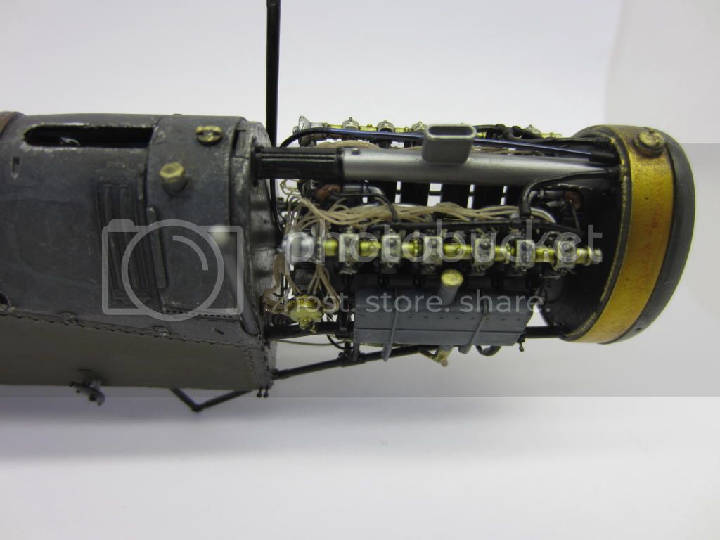
The system is two 6 lead magnetos. 12 plugs , 2 per cylinder. 2 tubes carrying 6 leads each. The top tube has 6 leads in ,6 out, ditto the bottom tube. Looking at the b/w image here you will see the front cylinder lead from the bottom tube clearly the rest not so much. The lead droops down under the tube then up into it. This is a 'drip loop' allowing water to drip off rather than wick into the tube.
I used ship modelling rope with model r/r eyelets to do leads on my Biff , which has 2 -12 lead magnetos:

I used ship modelling rope with model r/r eyelets to do leads on my Biff , which has 2 -12 lead magnetos:


JackFlash
Joined: January 25, 2004
KitMaker: 11,669 posts
AeroScale: 11,011 posts
Posted: Friday, June 24, 2016 - 05:19 PM UTC
Hey Steve! That is a fine build of the Rolls Royce for the Bristol Fighter, but he was looking for the The Mercedes D.IVa. He mixed up the designation in the thread title.
krow113
Joined: March 16, 2010
KitMaker: 473 posts
AeroScale: 101 posts
Posted: Friday, June 24, 2016 - 08:12 PM UTC
Quoted Text
Hey Steve! That is a fine build of the Rolls Royce for the Bristol Fighter, but he was looking for the The Mercedes D.IVa. He mixed up the designation in the thread title.
Yup no worries ,the thread is about high voltage wires for the D IV engine.,my first paragraph explains what the OP needs to know.
The pics are for reference of materials and a method for this work. My Gotha has the same engines ,DIV 's, I am in the GB on LSM's forum.
It should be said as well that WNW cast in plug landings on the right side of the engine as well, I was thinking of removing them as they are redundant.
phantom_phanatic309
#372
Joined: March 10, 2010
KitMaker: 2,568 posts
AeroScale: 1,619 posts
Posted: Friday, June 24, 2016 - 10:30 PM UTC
Quoted Text
Hey Steve! That is a fine build of the Rolls Royce for the Bristol Fighter, but he was looking for the The Mercedes D.IVa. He mixed up the designation in the thread title.
I'm going by what the kit instructions say. Says a D.VIa on the sheet, but D.IV on the sprue. As several parts on the engine sprue are unused and substituted for others from the rest of the kit, I assumed that was the reason in the different number. The mistake then is WNW's. I've since found a few other mistakes and I'm certain a couple of parts are misnumbered. It was what I had to hand when I originally posted. I stand corrected.
Steve, that's awesome work on that engine! I'll shop around and see if I can find any of that string.
krow113
Joined: March 16, 2010
KitMaker: 473 posts
AeroScale: 101 posts
Posted: Friday, June 24, 2016 - 11:18 PM UTC
Quoted Text
Quoted TextHey Steve! That is a fine build of the Rolls Royce for the Bristol Fighter, but he was looking for the The Mercedes D.IVa. He mixed up the designation in the thread title.
I'm going by what the kit instructions say. Says a D.VIa on the sheet, but D.IV on the sprue. As several parts on the engine sprue are unused and substituted for others from the rest of the kit, I assumed that was the reason in the different number. The mistake then is WNW's. I've since found a few other mistakes and I'm certain a couple of parts are misnumbered. It was what I had to hand when I originally posted. I stand corrected.
Steve, that's awesome work on that engine! I'll shop around and see if I can find any of that string.
No worries my pix were to illustrate a different magneto and HV lead system.
For the D IV engine I would use a single strand of copper wire , following the layout detailed in my first post. Taurus models has scale spark plugs, the HV lead clipped onto that . That's how I will do my Gotha engines , on the WNW site go to Gotha for more pix of the engine. There are oil lines, fuel lines , filters , clamps , radiator return line , etc , etc to be added.
 |

WEB HOSTING BY


Copyright ©2021 AeroScale and Kitmaker Network, a subsidiary of Silver Star Enterprises
All Rights Reserved. Please read our Conditions of Use and Privacy Policy.
All Rights Reserved. Please read our Conditions of Use and Privacy Policy.