 IMG_2187 by Chris WIlson, on Flickr
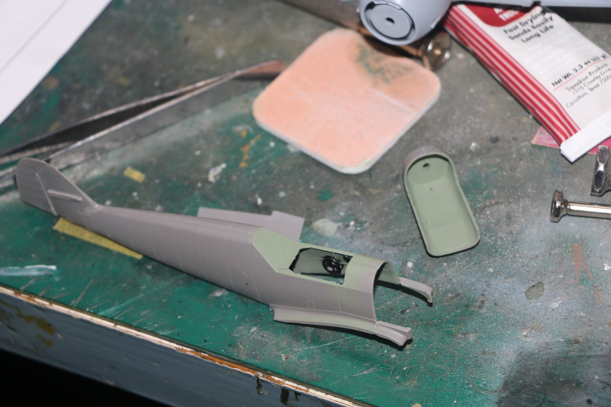 IMG_2188 by Chris WIlson, on Flickr
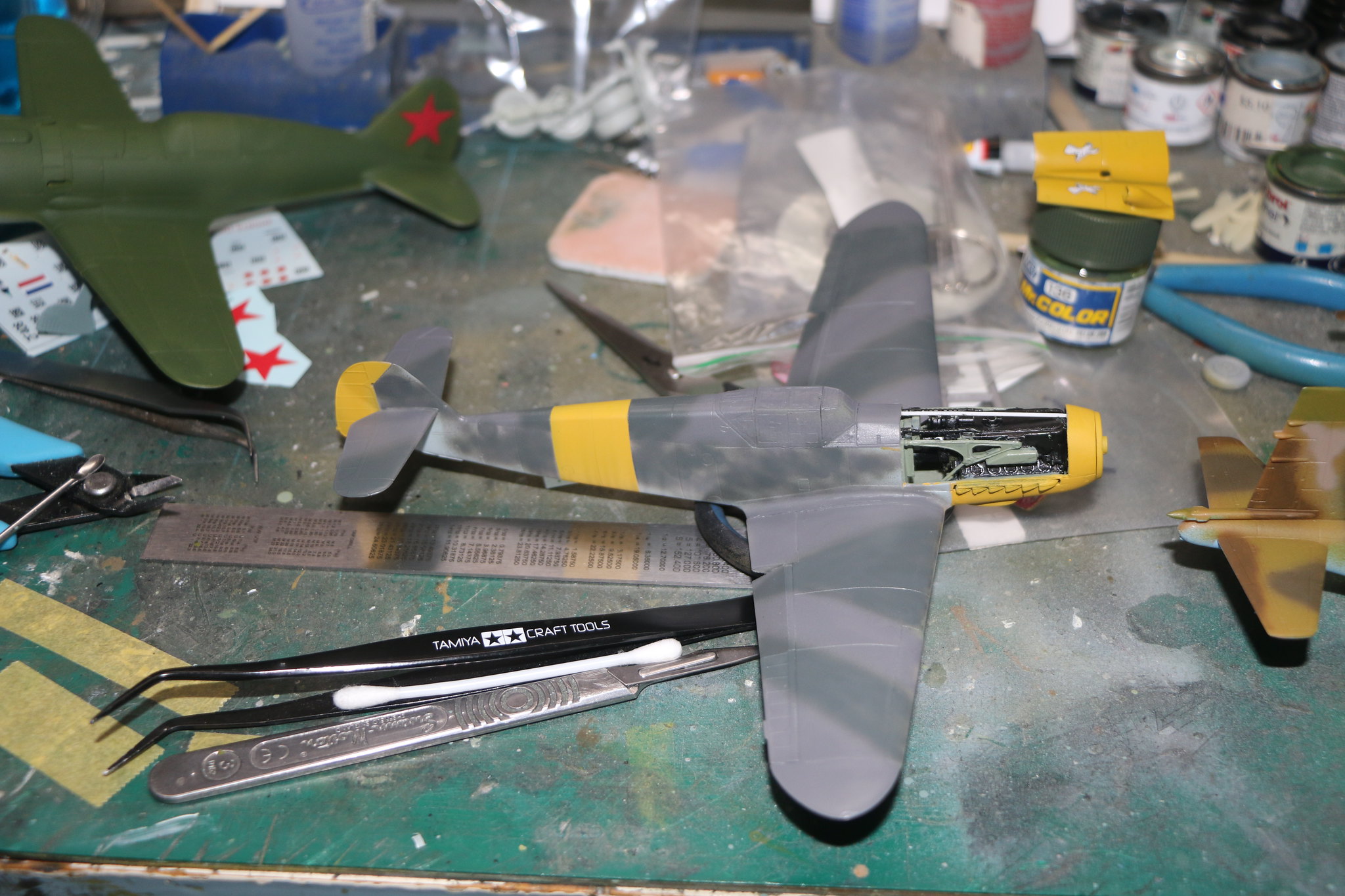
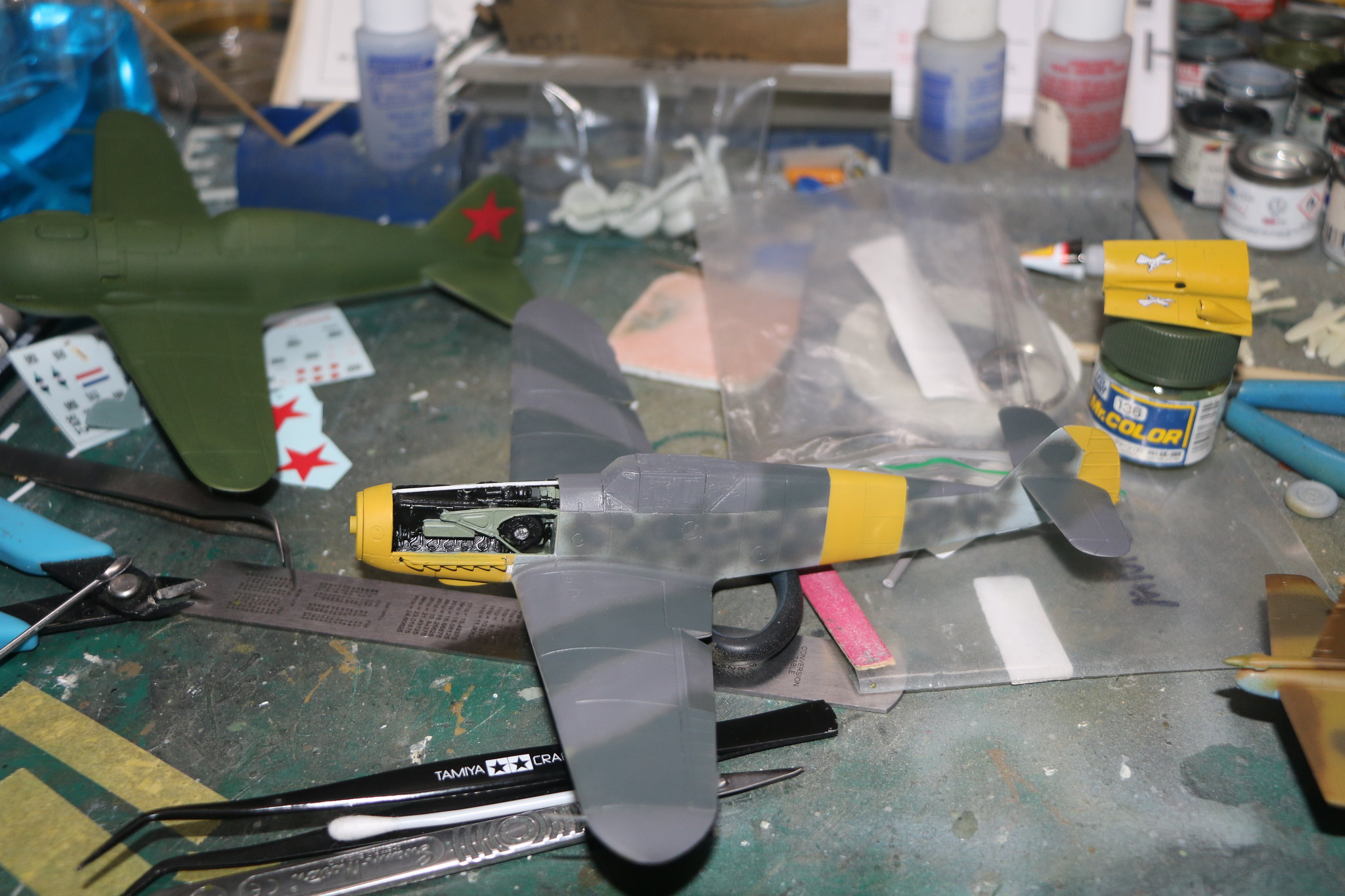
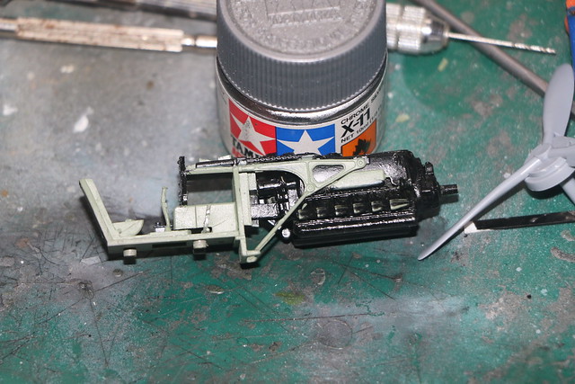
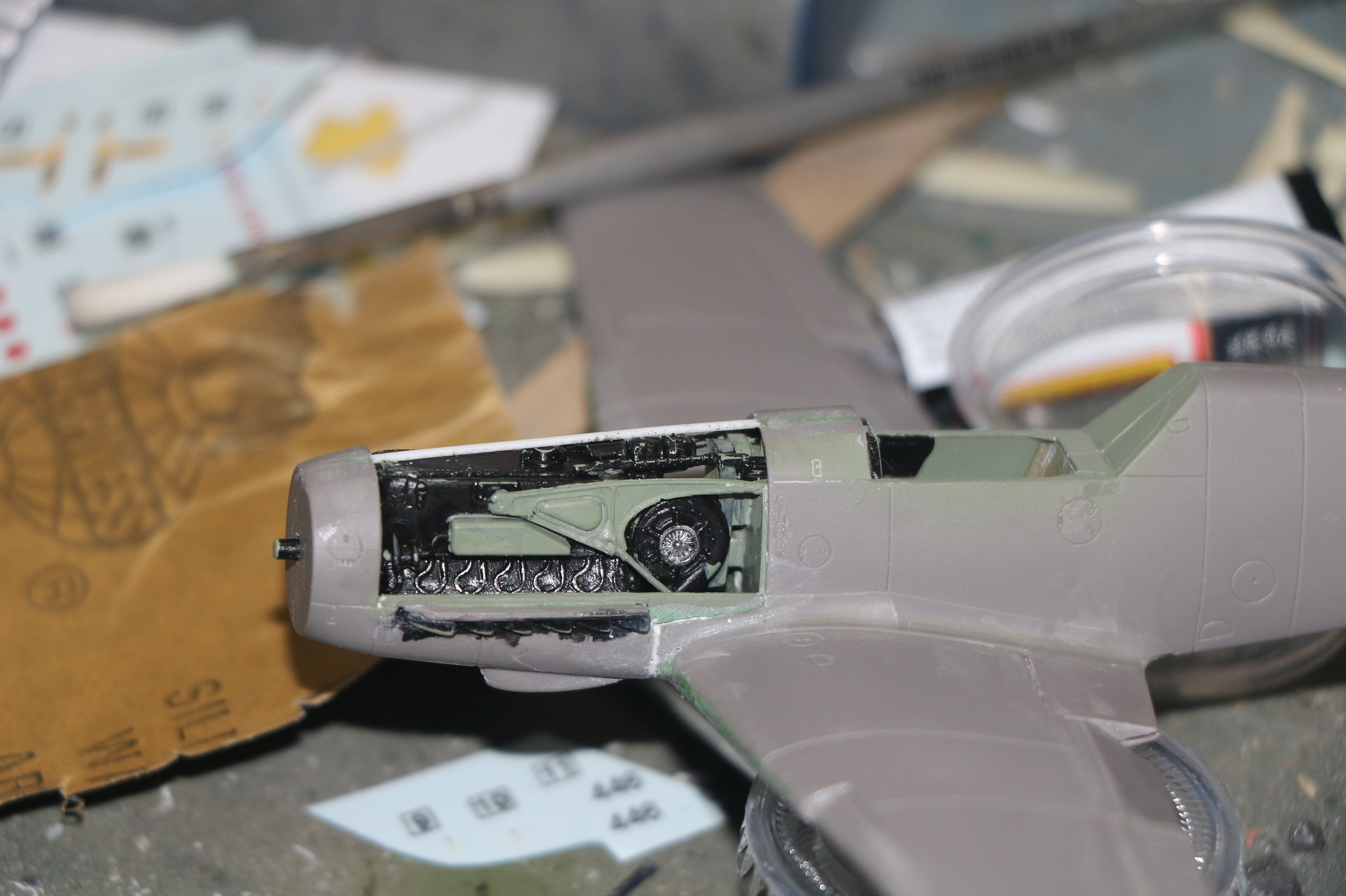
I've also found the instructions to be a little unclear as to where certain parts needed to go and I ended up putting the supercharger in entirely the wrong place. I found this out when I tried to attach the engine mounts and the one on the blower side wouldn't fit. Fortunately the plastic is soft and easy to work with so I manged to pry it apart and glue it in the correct place. Once there it became obvious where it needed to go.
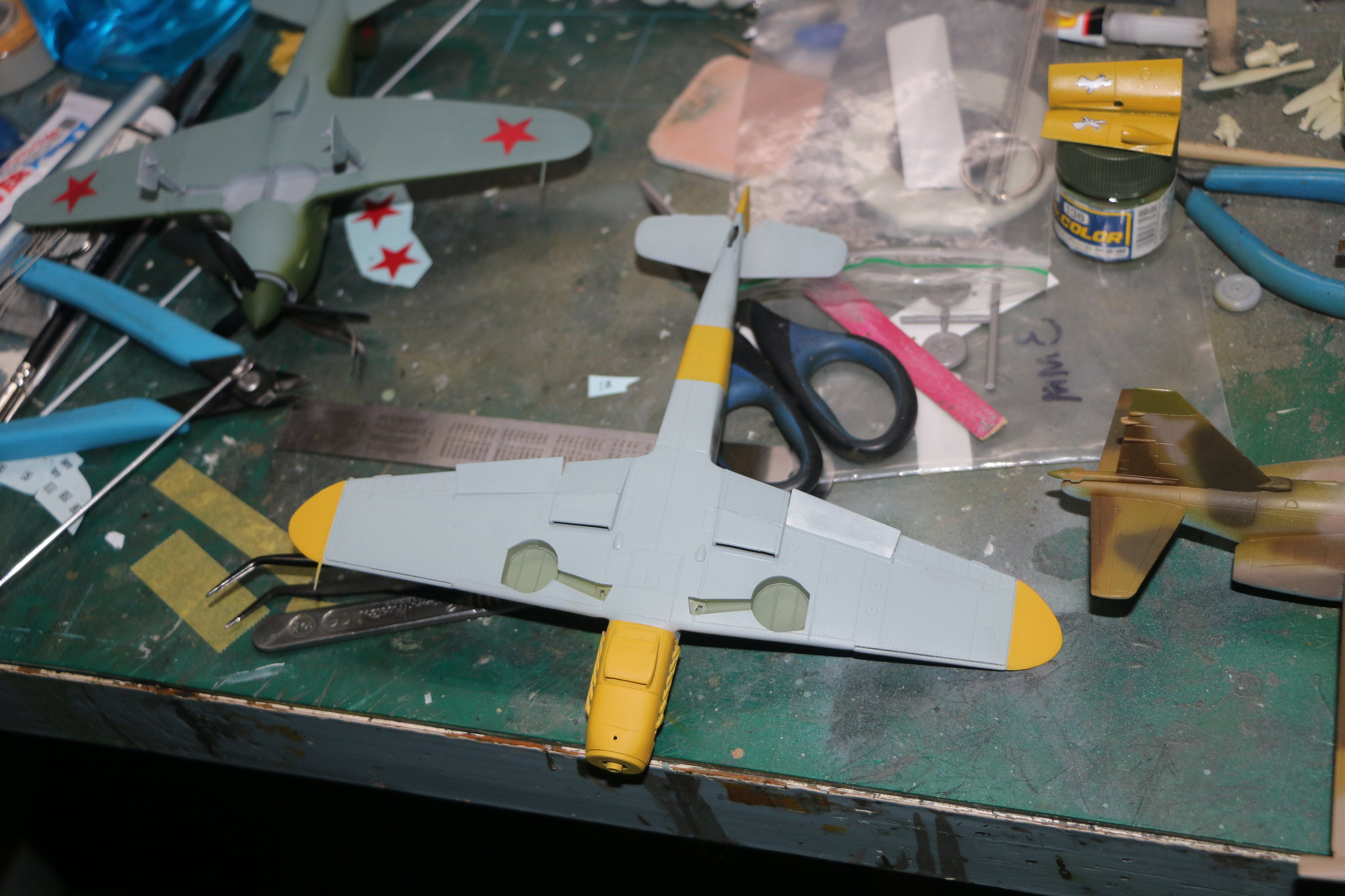
I've found the ICM kit to be tricky with the nose of the 109 being made up of several assemblies. This means there is a need for careful alignment. I thought I was doing great till I assembled the wings and the fuselage and found the oil cooler under the nose (another assembly) twisted to the left. Which made things a tad tricky to correct as I'd assembled it all together including the engine and mated it to the rear of the fuselage. When I build the next one (I have a Bf109F-4 to build) I'll follow the instructions and mate the wings to the fuselage first before assembling the nose around the engine. To fix the issue I used a fine razor saw to cut the oil cooler away from the fuselage and realign it correctly. I inserted a fine piece of plastic strip to fill the cut left by the saw and help with gluing it all back together. The strip can be easily seen in the following pics as it's stark white.
 IMG_2196 by Chris WIlson, on Flickr
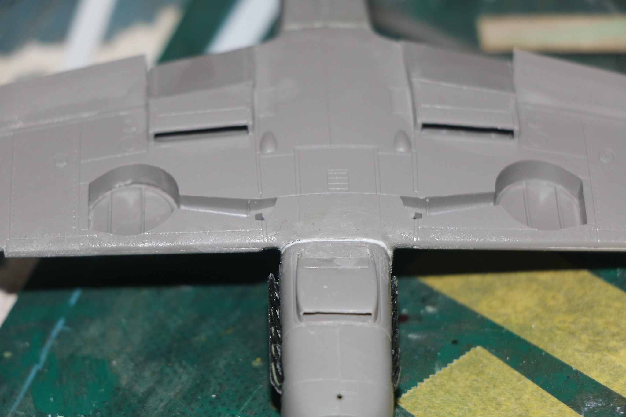
The right side wing to fuselage fit isn't good and needed more plastic strip ti fill it in. Only 1mm thick so not hugely out but fitting the wings when the instructions say to may have helped witht this also. This may make the kit sound like a lot of work but not really most of this was simply correcting errors that had crept in by my own hand. I've thoroughly enjoyed building this kit and figuring out how best to build it. I've got the interior painted and I'm working on displaying the cowls open to avoid having to close up the engine. Which I can do, just not easily as it seems I need an extra pair of hands to get everything aligned.
 IMG_2192 by Chris WIlson, on Flickr
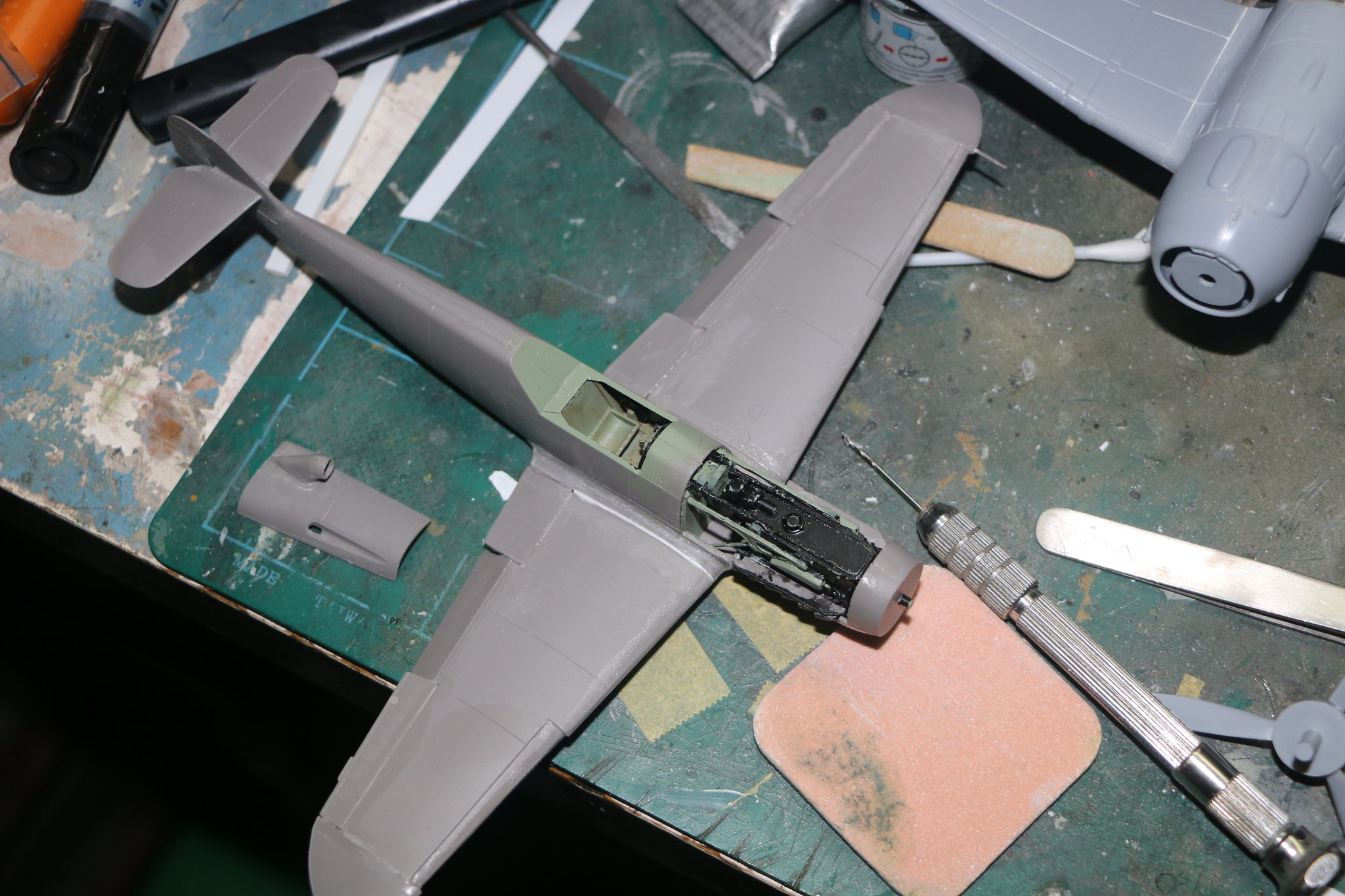
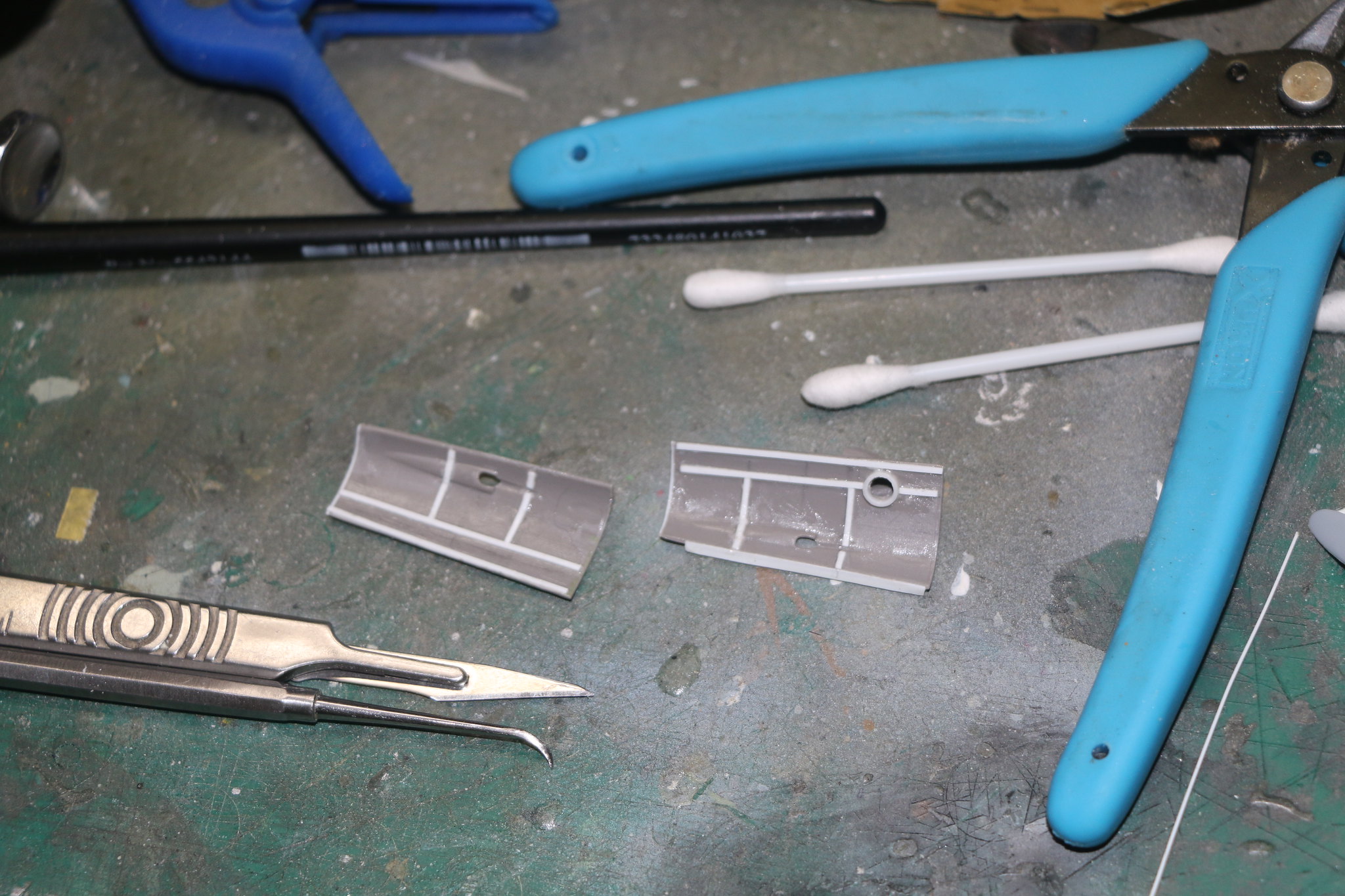
So I've been studying everybody else's build and I came to realise something that most had displayed the cowls open by simply gluing the panel open. However looking at pics online of the actual engine cowls it became clear that they needed to separated along the panel lines not simply just stuck in the open position. So I carefully scribed most of my way through the panel line and as the plastic is soft cut it the rest of the way through with a fresh scalpel blade.
 IMG_2207 by Chris WIlson, on Flickr
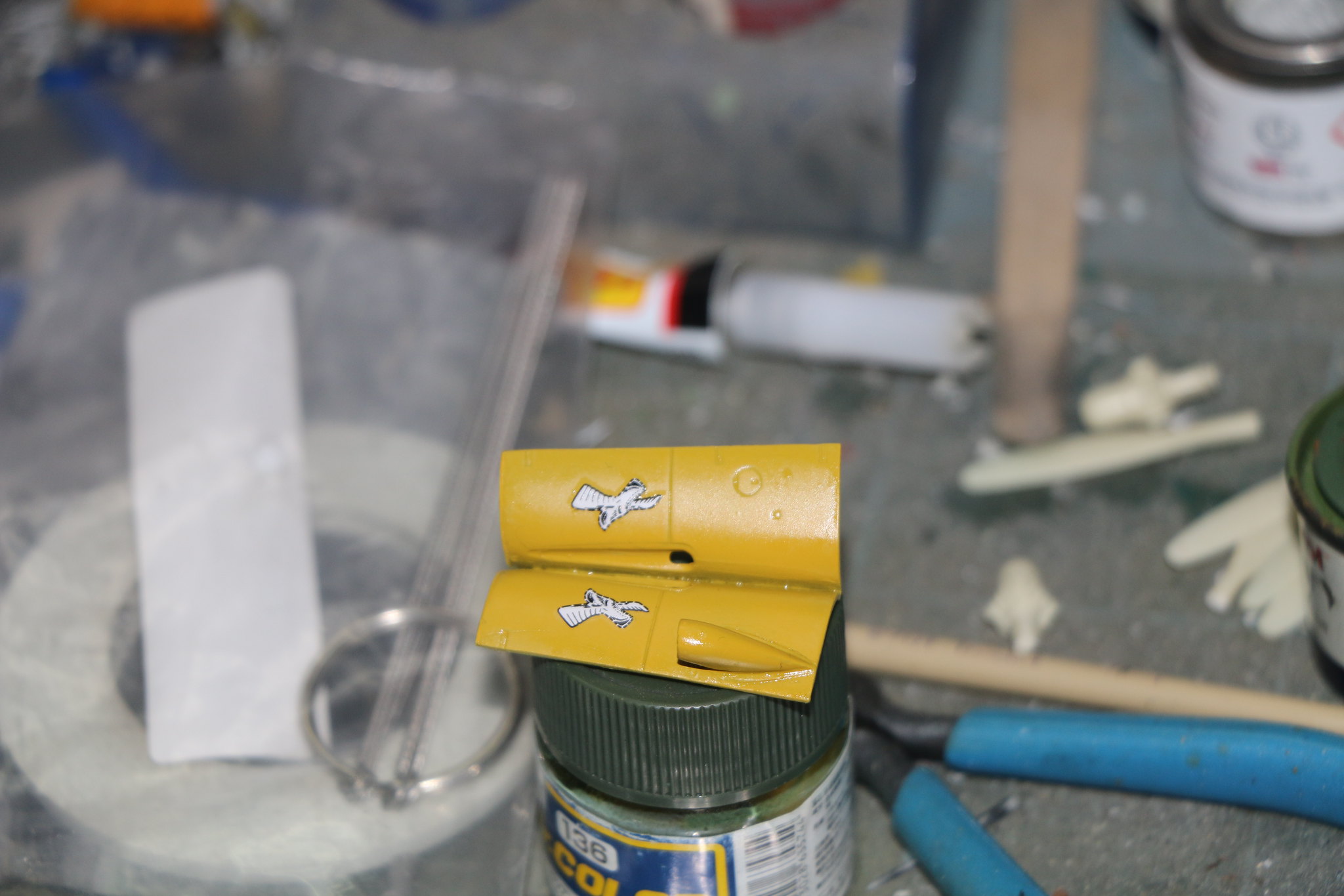
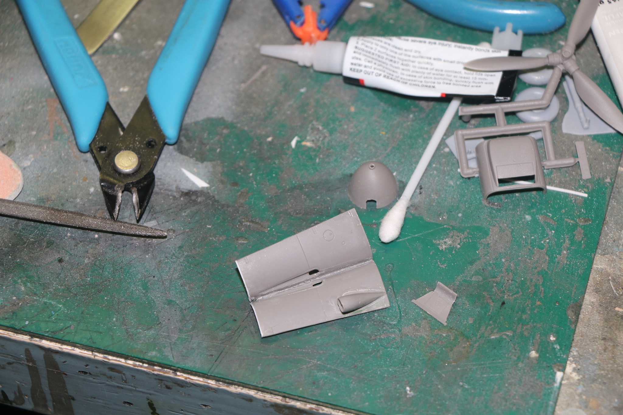
Also there is a support that runs down the nose to the spinner so the cowls can actually open which is not provided in the kit so I built one. There is no hole in the cowl under the air intake so I carefully drilled out the area and applied some circular plastic tube to simulate the joiner between the cowl and supercharger. I also roughly applied some bracing to the isnside of the cowls to get a close approximation of the real thing.
 IMG_2203 by Chris WIlson, on Flickr
I then joined both halves together and set them to oneside for painting. I glued a piece of plastic strip to one side to help when gluing both halves together.
 IMG_2210 by Chris WIlson, on Flickr
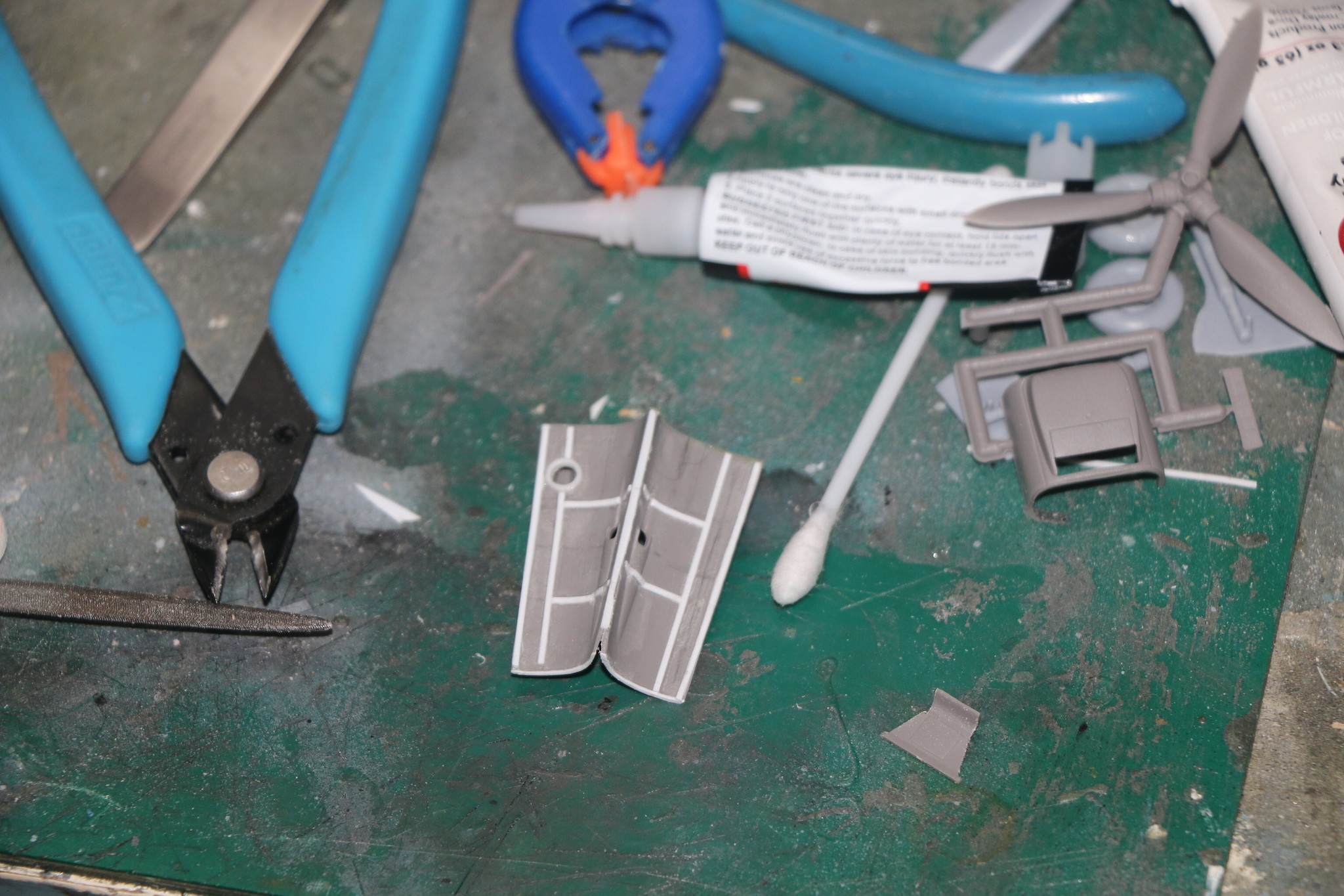 IMG_2209 by Chris WIlson, on Flickr