In printing the instructions Eduards scribes put an insert between page 2 & 3 of the instructions. We call them pages 4 & 5 and deal with them later.
Page 3.) When the fuselage halves (A 1 & 2) are joined you could add a section of 0.50 plastic to represent an oil tank. . Note that cowling A 14 is the type seen on the Nieuport 11 type only. Next scratch build the fuel and oil filler caps that will be adjacent to the Top Dead Center of the fuselage joints on the cowling (A 4 or 18 )and the upper section of the forward fuselage. Erase all seams in the fuselage union joints / seams.
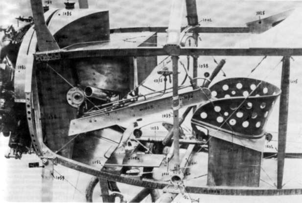
Now here is the fun part. This is a real 80hp LeRhone.
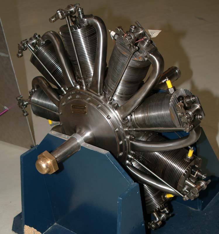
Eduard suggests you to take the 80hp LeRhône ( A 15 & B 16) that they provide you in the kit (normally for the Nieuport 11.) Then they want you to turn the whole assembly back to front. Since this places the pushrods and air induction pipes at what is now the rear face of the cylinders it almost looks like a 110hp LeRhône. Except!!! The induction pipes are now on the wrong side of the cylinders for a 110hp. Now there are two methods for reasonably modifying this kit item from an 80hp to a 110hp.
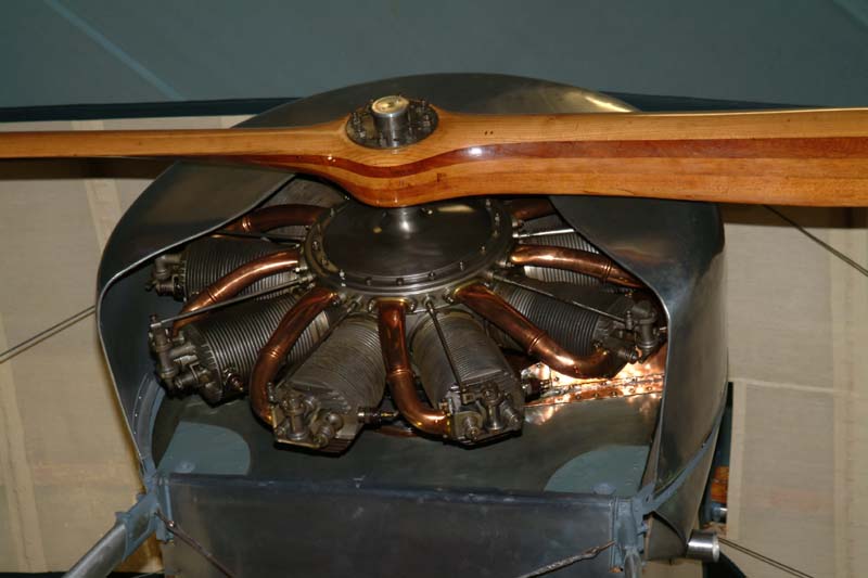
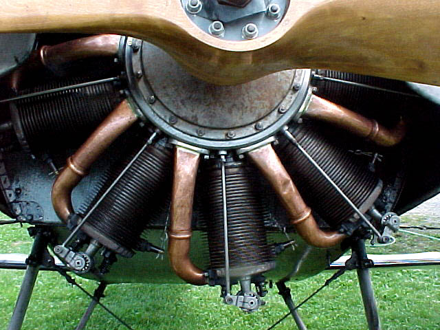
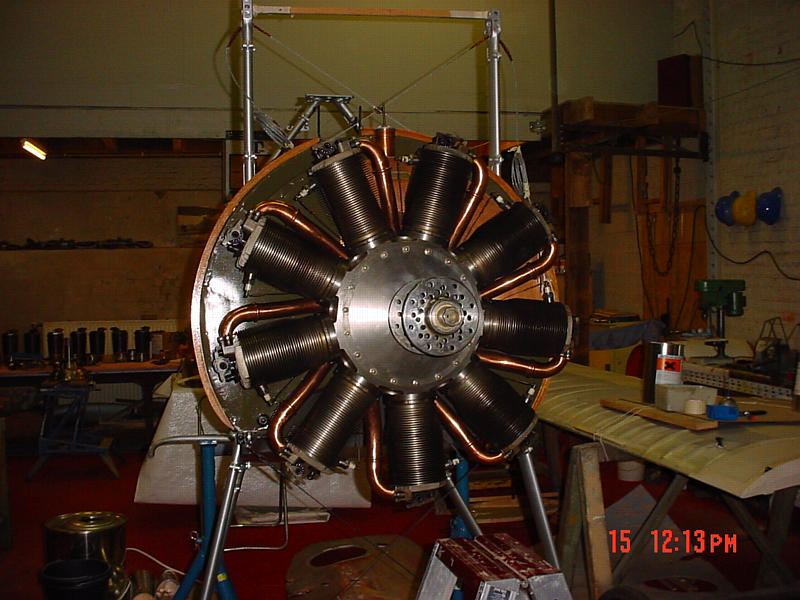
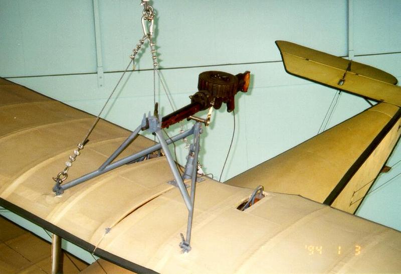
This is a real 110hp LeRhone.
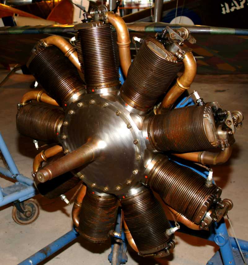
Reverse the cylinders and the crankcase ( A 15). Cut the induction pipes from the faceplate and scratchbuild them from brass rod. Now modify the face plate ( B 16) to sit flush on what is now the front of the engine. This method is the least labor intensive choice.
Note !!! You are going to have to modify the kit prop shaft (B 29. )
You will find it important to drill a small hole adding a section fine wire to the rudder (A 16) and its joint surface at the stern post of the fuselage assembly. You may want to add fine wire to the spark plugs on the engine cylinders (A 15) traveling back to the prop shaft assembly ( B 29). While this part is very simplified that is what it is supposed to represent. The exhaust cheek flanges are molded in place and could do with some opening and thinning at their bottom slots. Also note that the push rods are not included in this kit. There will also be a slight repositioning needed before glueing the base and the rod ends in place. Open the rigging and strut locator holes in the horizontal tail plane (A 5.) Check your references.
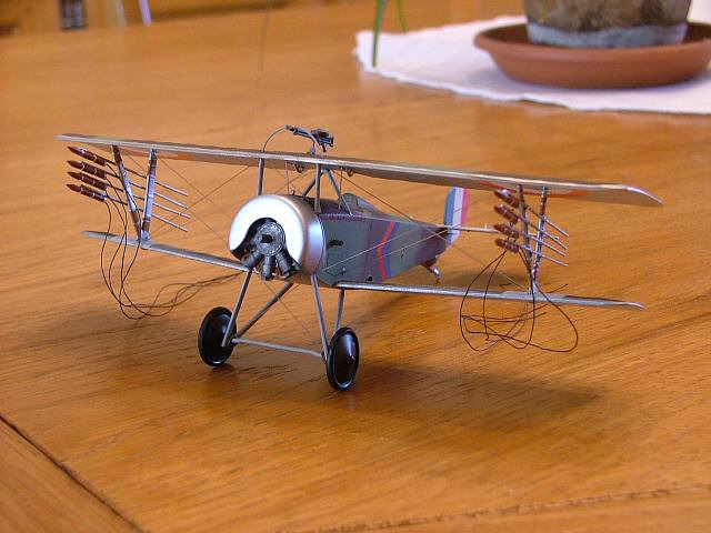
Next the front cabane struts ( B 31 X 2 .) The top wing ( A 4 ) should have a center line division running chordwise dividing the wing in half. Scribe a line to represent this, around the wing chord (upper and lower surfaces.)
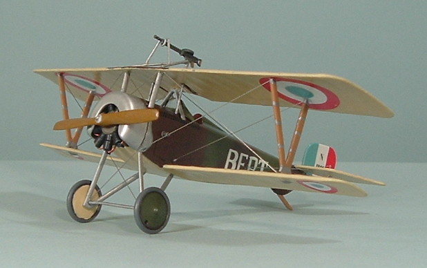
The Nieuport 11 topwing (seen here) is the same construction as the Nieu.16
The ailerons were hung using piano type hinges, no straps will be need to be added, check your references. Attach the top wing ( A 4 ) and set to dry in a Lego Block jig. When thoroughly dry begin the rigging process. Fortunately the Nieuport fighters are a good first kit for attempts at rigging a WWI aircraft. Remember always to drill the smallest hole to anchor your rigging material. The more lines to anchor enlarge the hole. Wait until the anchored lines have dried thoroughly. Pass the other ends through their next hole and hold them tight by clipping a spring type clothes pin to the lines end. Touch the smallest drop of Superglue (Cyanoacrylate) to the area and again wait til dry. Only a sharp razor knife should be applied to the loose ends of the strands. See page 4 concerning the Le Prieur rockets ( B 4 X 8 ) and their attachments.
These Photo images are from the WWI Modelers Page photo archive.