


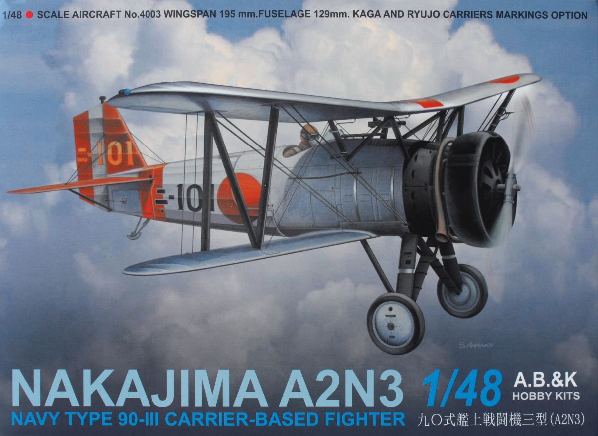
Are any of you interested in A.B.&K's 1/48 Nakajima A2N3? If so, join me for a build of this little beauty. You can find the review here: Nakajima A2N3 Navy Type 90-III Carrier Based Fighter.
A.B.&K's Nakajima A2N3 is a beauty and overall I am enthusiastic about it. So far I happily recommend this model for modelers with finesse to handle small, fine parts and components.
It seems as though A.B.&K's tool makers were trying to create as exquisite molds as possible; even the male-female alignment features are fine - not wispy nor delicate, but small. Trailing edges are equally thin. With that in mind, let's look at the assembly line.
AssemblyThose small, fine male/female part attachment points? Pay close attention to the pegs when cutting a part from the sprue.
Scrutinize the instruction sheet as there are a couple of tasks you will have to complete before some components are assembled, i.e., if you choose to mount the arresting hook (step
 , small divots are molded inside the fuselage halves that you have to poke open.
Starting with the first assembly, the cockpit, not many parts. Rudder pedals are molded onto the cockpit floor, and the rest of the cockpit consists of the rear bulkhead, instrument panel, seat, stick, and left and right cockpit side structures. Those side structures are tubing with a few boxes attached to them, but no switch/dial/lever detail is molded onto the boxes. The instrument panel is interesting with bezels molded around deep holes where the instruments are mounted. No dial detail is molded but decals are provided.
.JPG)
The deep voids worried me that the thin decal would be distorted as it settled into the dials. Amazingly, it did not and the printed instrument faces are more perfectly aligned with the molded bezels than my eyes could accommodate. I suggest using magnification when positioning the decal.
The seat features reasonably thin sides but no other detail. A.B.&K does not provide photo-etch for belts or harnesses. While the cockpit opening is small, one can see the seat clearly.
Steps 1 and 2 are assembly of the "office." The cockpit side parts (D12-13) have short pegs to mount into shallow dimples in the floor. They also have pegs on each end to fit into the rear bulkhead and instrument panel (part A5).
.JPG)
The instrument panel attachment is flawed as the mounting slots are molded into the wrong side of the instrument panel piece. Fortunately, the slots are easy of open with a drill or a sharp pointy hobby knife.
.JPG)
.JPG)
Mounting the cockpit assembly into the fuselage (step 5) requires you to fit the edges of the floor into slots in the fuselage halves.
.JPG)
To help align and steady the assembly, the rear bulkhead has pin that mounts into a shallow dimple in each fuselage part. But this exposed the first fit problem. The cockpit floor is too wide and I had to cut and file approximately 1/8th of an inch (3 mm) from one side. Afterwards, the fuselage closed up tightly. Aside from the empennage, the main fuselage assembly is complete except for attaching the engine and the forward fuselage cowling/decking (part A3).
.JPG)
.JPG)
Building the engine and cowl assembly are steps 3-4. Two exhaust collector collars and nine stub stacks attach to the back of the cylinders, and a cowling to the front. Step 4 is mounting the three-piece Townend Ring, or "drag ring" (parts A9-12: two variants) cowling. There is also part B4, a plate that secures the engine to the fuselage.

Recall I urge you to scrutinize the instruction sheet? Three cylinders have almost imperceptible tabs for attaching the cowling ring parts, and the engine must be aligned to mount to the fuselage properly in step 6. This is why I am describing the assemble of the fuselage and engine out of order. Once I figured it out it seems like a no-brainier, but identifying and orienting the various parts with their mounts was tricky. Or maybe I need to try this after my upcoming eye exam?
Step six attaches the engine, empennage, forward fuselage cowl/gun panel, windscreen, propeller, and the all important mating of the fuselage to the lower mainplane. Designing the mating of multiple compound curves tooled onto three separate parts gives me the utmost respect for the tool makers and A.B.&K deserves praise for how beautifully the parts fit. Aside from joining the parts with butt joints, two small tabs are molded to the fuselage halves to insert into two shallow slots in the wing.
.JPG)
I approached the process with trepidation but the fit is excellent and sturdy.

Alright, time to process some more photos, and then work some more on this gem. Check back soon!