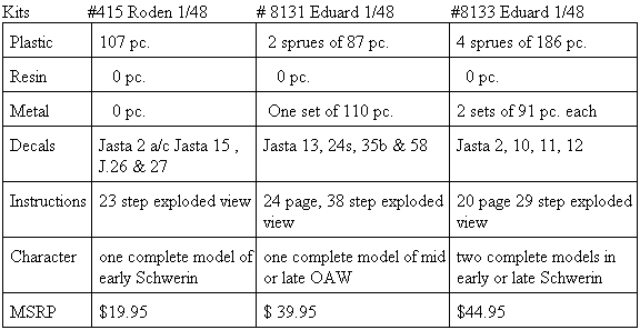
History
At the end of the war the allies wanted every example of the Fokker D.VII they could lay their hands on. The plants building them were the parent company of Fokker at Schwerin, also under license by OAW (East German Albatros Works) at Schneidemuhl and Albatros Works at Johannistahl. For the novice let me explain. The inevitable modifications that take place in each companys production series, of a specific airframe type, are described in linear terms of early, mid or late. Some of the readily visible hallmarks of these series are manifested in the different cowling panels, different applications of camouflage, cross type, size and position. Usually matched with the inline Mercedes D.IIIaü 180hp or the D.IIIav 200hp engine. But it was the variant with the BMW IIIa 185 hp motor that pilots prized ultimately. With few idiosyncracies it was not temperamental and a novice with a little nerve could do well.
Contemporary construction using welded metal tubing for the fuselage and wooden wing skeletal structures were typical. The secret appeared to be in the wing design of the cantilever boxed spars that eliminated the need for multiple exposed rigging wires. It was to become Germanys main production fighter in 1918 and was built in large numbers.
Twin Circus Thoroughbreds
Arguably the leader today in WWI aviation models, Eduard presented their newest offering in 2005 in their Limited Edition series. Now, in 2006 their 1/48 Fokker D.VII mold has just been released in the Dual Combo line and will be seen later in their Royal line. The Dual Combo is a pleasant surprise. As it costs about five US dollars more for two complete kits compared to the Limited Edition single kit. I will refer to plastic parts as PP and photoetch as PE.
It was on another black and stormy night, in the Czech Republic, lightning again ripped the skies near castle Eduard. Deep in the bowels of the old south tower, the ruddy skinned trolls work furiously packaging their masters new creations. A twisted set of boney hands nail the lids down on the deeply packed wooden oblong crates. In the eerie half light teams of tall draft horses hitched to heavy hay wagons shy and jump from the lightning flashes as if standing before the glue factory doors of eternity. As each wagon is filled to overflowing and its shrink wrapped cargo tallied for the final time, the goblin like drivers crack their long bull whips and the team disappear into the black void of night. Then, a thin, pale, tuxedo clad figure sweeps his high necked and flowing cape steps up to the huge oak doors and peers into the rain soaked night. One of the overseer trolls reaches with a twisted claw for the volume knob on the 1923 Philco radio and turns up the blasts of Edgar Winters Frankenstein. Moments later, suddenly the tuxedo clad figure cries out, That will do troll ...that will do!!! Thus another scale wonder is borne to the worlds hobby shelves.
Pages 1-3. Text and history. Eduard has modified the historical comments and corrected several misspellings from the very first and second issues of their kit #8131 to good advantage. Taking note from my earlier comments about his misidentification Reinhold Platz is now rightly identified in the Fokker history. The main alteration is the substitution of the fuselage sprues and the identification F replacing D. Express masks dealing with the colour profiles are limited to colour demarcations of the striping and wheel covers. Also there are the legend, parts map and colour references. Before beginning, wash your kit plastic in mild dish soap & water, dry completely, then pre-drill and clean up all rigging and strut locator holes.
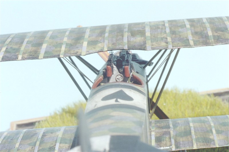
Page 4. The Mark Miller insets of the virtual engine and airframe components have been deleted from this set of instructions and as such has cut back on the number of booklet pages. The inline motor assembly is a generic representation that has pieces for the Mercedes D.IIIaü 180hp (PP B 5, 6, 8, 14 - C 4, 13, 34 ) or the BMW IIIa 185 hp assembly (PP B 5, 6, 8, 13 - C 4, 13, 34 .) Truthfully, most non WWI modelers wont know the difference. Check the references provided for some keynote differences in the types installed. The cylinder jackets of both engines were the color of blued metal. The BMW sat higher in the compartment so about 1" more of the cylinders could be seen. Its air induction pipes ( PP B 13) were unified where the Mercedes (PP B 14 )was divided. The immediate visual difference in the early Mercedes D.III 160hp / D.IIIa 170hp and its progeny the D.IIIaü 180hp or D.IIIav 200hp are in the rocker boxes above the cylinder jacket heads. On the early D.III and D.IIIa motors the rocker springs (B 6) are centered on the sides of the rocker box covers. On the D.IIIaü and D.IIIav motor the springs are located on the forward leading edge of the same covers. They were also that way on the BMW IIIa 185hp. The rest is below the cowling and not readily visible. Several good manufacturers ( specifically Roden) note the difference and have two distinct castings. The Mercedes D.III160hp was outclassed by 1917. The Mercedes D.IIIaü 180hp was the standard engine in both of the Albatros late built D.V and all D.Va types starting in late 1917 and then the Fokker D.VII through 1918. Then in early 1918 came the Mercedes D.IIIav 200hp. The BMW IIIa 185hp was highly prized by pilots. Many, many D. III and IIIa type motors were rebuilt to the D.IIIaü specs at the airparks as the war progressed. That is why some captured examples had motors with the i.d. designation of D.III 160hp cast into their crankcases. This has caused the misconception that the standard 160hp and 170 hp were used in 1918 at a time when they had become obsolete. Often these were referred to as 160hp over-compressed engines.
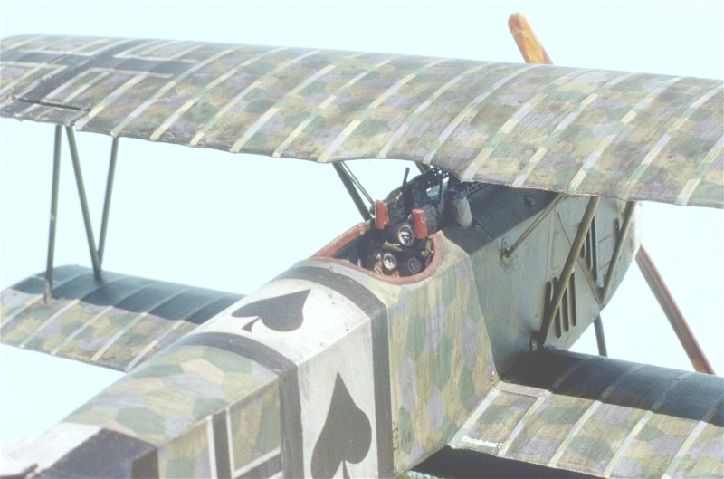
Next the cockpit flooring (PP A 7 ) The rudder bar ( PP C 33 ) inserted through the flooring (PP A 7) and needs a vertical bar attached centrally. Like the DML Fokker Dr.I set up, this vertical column should angle back and up behind the ammunition box (PP A 16.) On the control column (PP C 27) note the throttle lever has one handle We also have photos where two are present. Check your references. Set the rudder bar (PP C 33 ) to the desired position to compliment the attitude you have chosen for the rudder. Scratchbuild an aileron control V for cables and attach the V at the front end of the lower control bar molded to the cockpit flooring (PP A 7) . Also add the compass ( PP C 14 & PE 10.) Also here, add bent and shaped brass wire for the throttle and the cables for the Spandau machine guns. Later you will have to add all the control rigging material to the elevator control column(PP C 27 ) and the rudder bar column (PP C 33 ) when the cockpit rear bulkhead / screen (PP A 11) is added. Some of these cables should to go through holes that you need to cut in the rear bulkhead / screen (PP A 11 .) Check your references for the various cables and wiring that are attached to these units.
The seat (PP B 12 & 15 ) sets into its supports that are to be built up in a box frame ( C 17, 18 & 32) and attached to the rear cockpit bulkhead / screen (PP A 11.) I trimmed down the inside surfaces of the seat ( PP B 12.) ( The seat was known to be covered in fabric that was held by attaching it to eyelets in the seat backs outer rim.) I also deleted the seat cushion (B 15.) As parachutes had come into use the seat was made deeper to accommodate the chute pack as a cushion. There was not any tucked leather or buttons on the chute pack surface. In the cockpit rear bulkhead / screen (PP A 11) note there needs to be holes for the rudder control cables to pass through. Next remember the rudder control cables that will be added between the bar and the stirrups will need to go through these holes. Whatever the fuselage covering use the same covering on the bulkhead/screen (PP A 11.) In this case of 4 or 5 colour lozenge. The pilots shoulder harness straps (PE 1) are attached to the seat framing (PP C 18)behind the seat (PP B 12.) Next the location for the fuel pressure hand pump ( PP C 10.) You my want to add a half loop of painted brass wire to simulate the air hose leading toward the front of the cockpit strapped to the framework.
Page 5. First of all choose which fuselage versions you are going to build. You can replace the molded cockpit structure in the fuselage halves (PP F 1-3 , 13 ) with painted brass rod sections or after you apply the interior surface lozenge decals and they thoroughly set, dry brush the details with a light grey or grey-green to bring out the airframe skeleton. Note that the factory printed lozenge pattern fabric used on the Fokker D.VII showed through the interior of the cockpit sides in reverse in lighter shades. For the exterior the kit supplied four and five colour lozenge colours are way too light. But in an attempt to help the modeler work with what comes out of the box I will offer a fix. A wash coating of translucent dark blue and / or black tends to help greatly. I have to admit that this is one of their better efforts to provide the lozenge camouflage compared to what they have offered in the past. I prefer the Eagle Strike lozenge decals instead of the kit provided items. Their clear carrier film on the lozenge decals allows them to be easily reversed. Just apply a little decal Sol & Set.
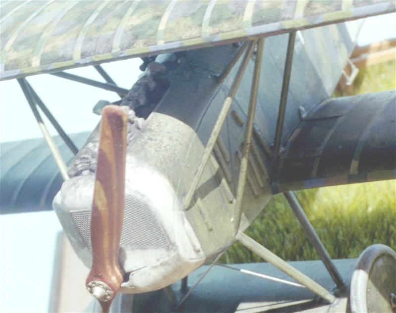
There is no main fuel, reserve fuel & oil tank assembly. Then we see the method of attachment of the engine and the typical Eduard bearing shelf to the raised edges within the engine compartment. Note Eduard has provided for a vertical installation of the Firewall (PP A 8.) This is incorrect. This should have an incline at the top toward the engine compartment with a cutout for the engine decompression bell. To do it right you will have to erase the forward most, lower locating ridges. Then line the rear face of the firewall up on the outside of the forward most, upper locating ridges. On the early Schwerin fuselage (PP F 2 & 13) without louvres its not too noticeable. Out of the box the pilot's right side upper engine cowling has a larger cutout for the cylinders and exhaust opens up that area for scrutiny. On the Late style Schwerin version (PP F 1 & 3)out of the box the cowling opening for the engine cylinders is larger and easier to see the firewall is too far back.
Concerning the instrument panel (PP A 14 or PE 14 & 15 ), I will usually paint Fokker company instrument panels black and give OAW or Albatros types a varnished wood look. Eduard has pre-painted theirs a drab brown colour. They have also given the modeler a great set of photoetch instrument panel parts and fuel gauges for two complete kits. I also added a hand crank spare part as a handle to magneto and flip levers (PE 25 X 4) to fuel and air controls. I also add the tachometer (PE 11) dial to the machine gun rear brace (PP C 28.) Finally they discuss the engine compartment assemblies. As mentioned earlier cowling side panels are a known hallmark in determining the parentage of your D.VII. But in mid-summer these items upper cowlings would be removed during flight operations. This would be typical of a machine in mid to late (June - Nov.)1918. The late Fokker types came to the front on very late summer early fall (autumn) 1918. Now assemble the fuselage halves (PP F 1- 3, 13) with its internal component assemblies.
Page 6. Here we assemble the lower wing parts (PP A 2 & 3, B 1.) One could actually insert spars held in place with double sided tape or glued in place. This type of wing assembly is great for the modeler who wants to simulate damage. By thinning down the inner surfaces, internal structure is easy to replicate. Also, before putting the lower wing together sand the vertical edge of the lower wing at the roots of all three lower wing components (PP A 2 & 3, B 1.) The unmodified fit between the lower wing an fuselage is tight and cause anhedral just like the Roden kit. This fix will eliminate the fit problem. Do Not narrow the whole fuselage by taking away from the center union area.
The fuel gauge (PP C 16) can have a decal(#30) or a metal gauge face (PE 12.) Note that the large ammunition round counter gauges (PE 5 X 2) are located on both sides of the machine gun rear brace (PP C 28 ) not just one. ( On page 7 you will have the option to install smaller round counters (PE 6 X 2 ) directly to the gun breeches.) The radiators (PP F 7 or 11) have plain internal faces and no shutter assembly. Eduard chose completely enclosed cowling types and thusly no detail was added. The early and mid production versions were known to operate with upper cowling panels removed during the hot summer months. Check your references. If you decide to open up this area, you may need to alter the rear face of the radiator (PP F 7 or 11) before you attach it. By scribing some crisscross lines in the rear face of the radiator you create a better simulation. Also the radiator fillets (PP F 12 or 14 - mislabeled on the parts map as another F13) are given for two aircraft. After painting or decal applications, assemble the horizontal stabilizer (PP A 10.) Eduard has given the modeler an easy way to deal with the undersurface fuselage fabric seam (PP C 21.) A first for WWI aviation modelers. The altimeter gauge ( PE 5 ) is optional as some pilots used wrist watch sized types.
For the exhausts (PP F 8 - 10 ) Mr. Pete Grosz tells me that there were at least six manufacturers putting out these exhausts. The instructions take this time to discuss the application of its lozenge. For me it seems that this should have taken place a page back before assembling the major components. See the rear cover of the instructions for more. Next comes the rudder (PP A 12) and stabilizer fin (PP A 15 ) and control horns ( PP C 3 X 2.) On the original aircraft these items were covered in normal fabric (either plain or lozenge depending on the batch) and the white areas were then painted in place. Next, werke numbers, factory serials and rudder cross were applied. I would now add the control horns (PP C 11 X 4) and let dry. As this begins to dry set the attitude of the elevators (PP A 17) that you wish to reflect. The four plates are hinged panels (PE 4 X 4) to access the lower wing spar attachment for the fuselage. Note these should have the triangular plates (PE 26) on the fuselage, located immediately above the hinged access plates (PE 4 X4.)
Page 7. The kit provided Spandau machine guns (PP A 5 X 2 ) are entirely plastic. But Eduard gives you etched metal the fretted jackets and other details (PE 6, 20, 21, 23 X 2.) The empty belt chutes (PP C 2 & 7) attach next. The completed Spandau machine guns should be painted in semi gloss black. All German issue Spandau and Parabellum machine guns came from the factory with the outer surfaces covered in a baked on black enamel. Some highlighting in gun metal colouring maybe appropriate. You have the option to install smaller round counters (PE 6 X 2 ) directly to the gun breeches. On the previous page larger versions were discussed.
The Eduard top wing assembly (PP A 1, 4, 9 B 2) does not have the mold casting problem found in most of the DML / Dragon kits. By this time I have painted and added decals to all completed wing surfaces and they are thoroughly dry. As mentioned earlier his type of wing assembly is great for the modeler who wants to simulate damage. By thinning down the inner surfaces, portions of internal structure is easy to replicate. For those of you with AMS - a strip of 20 thou strip could be added between the cabane attachment points out to the leading edge mating surfaces of the top wing. It helps the Eduard wing match the wing thickness shown in Anthology 3. Otherwise the wing will be too thin seen from the front. Even with this easy mod, it's still not as deep as the Roden wing, but that may item be on the too thick side. Add the control horns (PP C 11 X 2) next. More is discussed here about the Lozenge placement. See the rear cover of the instructions for more.
Page 8. To bring the fuselage and top wing assemblies together I use childrens Lego blocks. to form a jig to keep everything level and square. Then add the interplane (PP C 5 X 2 ) struts first, then the cabane (PP C 9, 15 30 & 31) struts. The anemometer ( PP C 29, PE 9) is an air speed indicator. The plastic struts are commendably thin and clean up quite nicely. My own opinion is that metal etched or white metal load-bearing struts or supports gives a build a much greater longevity.
Page 9. Continues the cabane strut (PP C 9, 15 30 & 31) attachment details. Next the horizontal tail unit stabilizer struts (PP C 20 X 2 ) and the tail skid (PP C 12.) I did replace this item with a modified brass rod for strength. It looks like Eduard originally forgot to add two control horns (PP C 11 X 2) to this image. On the Schwerin built machines the grab handles (PP C 8) do splay out about -30 degrees from the fuselage.
Page 10. Is the axle wing (PP B 7, F 5 & 6 ) and wheel (PP F 4 X 2) assemblies. With the wing axle mid section (PP B 7) I routed out the plastic axle and replaced it with a brass rod of appropriate diameter. Next add the landing gear legs (PP C 23-26 ) to the wing axle (PP B 7, F 5 & 6 ) There are four propellers of two types offered by the kit. Axial (PP B 16 ) and Heine (PP B 17) and note that Eduard has referenced the right application to the profile provide in the kit decals. The problem is that the Heine propellers (PP B 17) are far too short for inline six cylinder engines and should be closer in length to the Axial (PP B 16) types provided. Two of the four kit propellers with the cones on the bosses are quick release items seen on some BMW engine variants only. It is the pitch and length of a propeller that determines the engine application. The paddle profile was the company hallmark.
Page 11. The half moon strut attachment points(PE 26 X 8) that Eduard include as photoetch are for the underside of the top wing assembly are a nice touch to add as well. Rigging paths are shown in thin red lines. There should be four aileron actuation cables (two on each side for the fuselage) running up into the area behind the rear cabane struts (PP C 9 & 15.) Check your references.
Decals
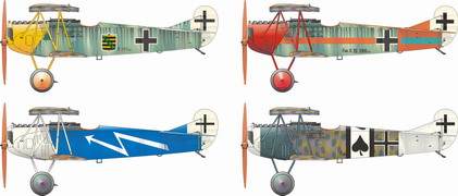
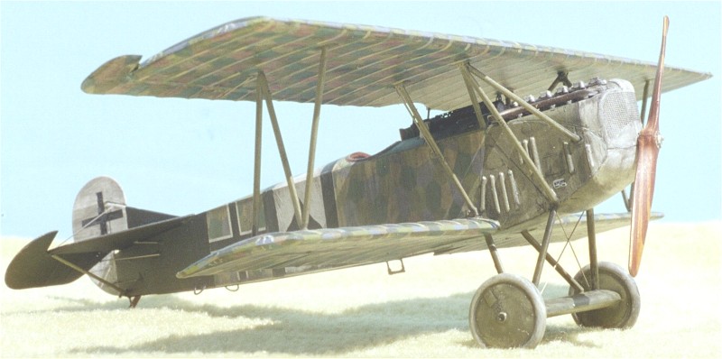
Pages 12 - 13. Offiizierstellvertreter (acting officer) Paul Aue http://www.theaerodrome.com/aces/germany/wedel2.htmlof Jasta 10 was a Saxon native. He began his career in Kasta 30 of K.G. 5 in 1916. Of his ten victories four were achieved flying the Fokker D.VII. Eduard has extrapolated the serial as 263/18 but in reality it is unknown. Also all wing mounted national crosses were over painted Iron crosses representing the early Balkan crosses and should all have broad white borders seen upto June 1918. The kit decals do have the late versions seen after July 1918. Most authoritative sources say that this machines wings was covered in four lozenge fabric on the wings. The horizontal tail plane should be painted in a similar manner as the fuselage not covered with lozenge. I would replace the fuselage cross as well with a thicker version typically seen on this production batch. The rib tapes would also be lozenge.
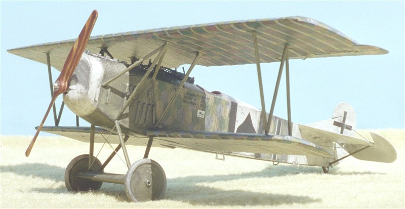
Pages 14 - 15. For the scheme of Jasta 11 pilot Vizefeldwebel (acting sergeant) Willy Gabriel Eduard provides a colour plan view of the final version of his paint scheme. Note that the orange chevrons / stripes - only, are included by design. This gives the builder the chance to use his model paints for the light blue match the whole scheme. The light blue rib tapes are typical for OAW machines not early Schwerin types. While Eduard was showing some forethought, consider that Gabriels D.286/17 scheme was NOT completed in a short period of time. Having the various orange and light blue painted locations not completely match, may be more accurate.
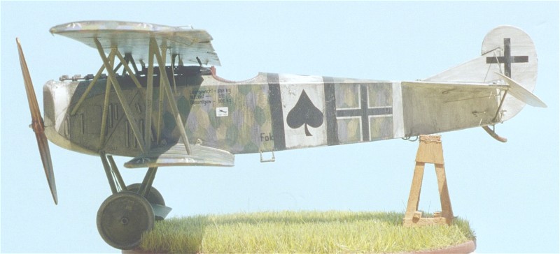
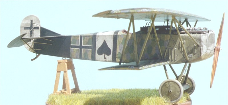
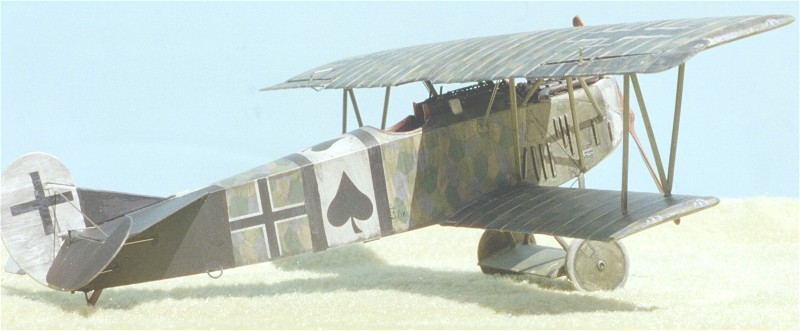
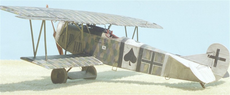
Pages 16 -17. Eduard has mistakenly replaced the arabic numbers of 11 for the Roman numerals of II for identifying what should be Jagdgeschwader II of which Jasta 12 was a component. The serial number of Ltn. Des. Res. Alfred Grevens Schwerin machine is unconfirmed. A four victory pilot had the same blue fuselage / white lightning bolt scheme painted on several of his mounts. Known to have a BMW engine the guns should be raised slightly. Ltn. Greven probably flew this Schwerin mount at the same time as an identically marked late Fok. D. VII OAW.
Pages 18 -19. Even with recent studies of Jasta Boelcke machines, the identity of this machines pilot is shrouded in mystery. So Eduard tries to speak to the history of the unit itself. But their new four and five colour lozenge camouflage decals have their strong points and prove that Eduard is finally moving in the right direction. Note also that the four colour lozenge has two colours assigned to the wrong lozenge shapes and we note that they are trying to improve. If Eagle Strike is an A then Eduard's is a B . You have to give them credit. Both of the kit supplied four and five colour lozenge will benefit from a translucent coating of dark blue or black overall.
For this kit of the Fokker - Schwerin the light blue or the pink rib tapes are not appropriate. To be accurate they should be clear doped linen or lozenge. The examples we have in the Lafayette Foundation show that the rib tape was used in one piece on the whole wing rib profile. In general, from the factory Fokker Schwerin used lozenge or clear doped linen strips, OAW used light blue and lozenge and Albatros used salmon pink and lozenge. Though Eduard has rightly used the same colour rib tapes on top and bottom of the wings. Note also that there are cases where whole wing components were mixed at the unit level as replacements. That is the lower wings were one component and the top wing was another. Check which profile you intend on doing.
Historical colour notes
Noted historian Dan San Abbott has offered this comment. Fokker D.VII machines, D.227/18, 228/18 and 229/18 were completed camouflaged in the streaked system. Commencing with Fok.D.VII 230/18 through D.374/18 had the fuselage, axle wing, stabilizer, elevators and fin were streaked dark, (*26F8) to light green (*26D3)on the top and side surfaces and greyish green) (25C5)on the under surfaces...Concerning the wings commencing with Fokker D.VII 230/18 to at least D.526/18 the wings were covered with Four Color Printed Fabric. Commencing with serial number D.377/18, the fuselage and empennage were cover with printed fabric. Some of the early machines had the fuselage and tailplane covered with five color fabric, Fokker D.VII 402/18 is an example. Most Fok.D.VII fuselages and empennages were covered with Four Color Printed Fabric. In the late production batch, D.7604 to 7805/18 when the five color fabric was introduced on the complete airframe on, or about Fok.D.VII 7788/18 and on subsequent D.VII aircraft. To clarify the situation, Fokker Flugzeugwerke made the fuselage, axle wing, and empennage, while the wings were made by Perzina Pianoforte Fabrik and were covered with four color fabric...
* = Methuen colour coding.
References
Albatros D.Va German Fighter of World War I by R. Mikesh, Smithsonian Inst. Press, Pp. 48-53, 1980.(great engine details.)
Combat Colours #14 The Fokker D.VII by P. Cooksley, Airfix Magazine. Date unknown.
Details & Colours Windsock Intl. Vol.3 #3 Summer 1987.
Fliegertruppen #2 by A.Ferko, Privately Published, Salem Ohio, 1987. (photocopies may be obtained by contacting the University of Texas at Dallas through the special aviation collection.)
Flight Report Cross & Cockade Great Britain, Vol. 2 # 4.
Fokker D.VII pt. I DML - Grooming a Thoroughbred' Model Aircraft Monthly Jan. 2003.
Fokker D.VII pt. II Jager, A Horse of a Different Colour Model Aircraft Monthly Nov. 2003.
Fokker D.VII by Egon Kreuger, Profile Pub. Ltd. 1962.
Fokker D.VII by P. Grosz, Albatros Pub. Ltd, Datafile #9. 1989, 1993, & 1994.
Fokker D. VII Aces of WWI, pt. I by Franks & Van Wyngarden. Osprey pub. 2003.
Fokker D. VII Aces of WWI, pt. II by Franks & Van Wyngarden. Osprey pub. 2004.
Fokker D.VII Anthology 1 by R.Rimell, Albatros Pub. Ltd. 1997.
Fokker D.VII Anthology 2 by R.Rimell, Albatros Pub. Ltd. 2000.
Fokker D.VII Anthology 3 by R.Rimell, Albatros Pub. Ltd. 2002.
Fokker D.VII Kit Survey by R.Rimell, Albatros Ltd. Windsock Vol 13, #4 1997.
Fokker D.VII Covering Practices by Dan-San Abbott, WWI Aero #102, Pp.22-33. 1984.
Fokker D.VII Detail Marking and Finish of Fokker-built D.VII Aircraft by Dan San Abbott, WWI Aero #107, 1985.
Fokker Fighters of WWI by A. Imrie, Osprey, Vintage Warbirds #6 Pp.41-64 1986..
Fokkers Last Deadly Scourge by M. OLeary, Air Combat, Pp. 18-26. 1975.
Forgotten Fokker by P Cooksley, Cross & Cockade GB Vol.4, #2,Pp.84-86. 1973.
German Army Air Service in WWI by R.Rimell, Osprey, Vintage Warbirds #2, Photos 42-44, 1985.
Germanys Last Knight of the Air by C. Degelow, William Kimber Pub. London, 1979.
Jagdgeschwader Nr. I by Greg VanWyngarden, Osprey,Aviation Elite Units 18. 2004.
Jagdgeschwader Nr. II by Greg VanWyngarden, Osprey,Aviation Elite Units 19. 2005.
That Fokkers an Albatros! By Wally Tripp, WWI Aero, #102 , Pp.14-21. 1984.
Udets Fokker D.VII Fighters by Dan-San Abbott, Windsock Vol.4, Spring 1989.
Wings of War by R. Stark, Arms & Armour Press. 1973.
Comments
In my opinion, Eduards kit is a finely cut mold. The new generation exploded view instructions are great. The rest of the kit is well tooled and has become a standard. The average modeler can pick this kit up and get very decent results. Then it exceeds our expectations when we consider a double kit that has almost everything the modeler wants in one box, for five dollars more than a single model kit. It has great plastic with two options for two aircraft, optional photoetch and precut decal lozenge and a comprehensive slick paper magazine for instructions. This Eduard kit is a nice bargain.