Described variously as a Vicious little Beast and the King of Combat the Sopwith F.1 Camel was by all accounts anything but docile. In the hands of a capable pilot she was a force to be reckoned with. Much has been written on this bird of prey both pro and con. One source says that Camel Drivers accounted for more enemy aircraft destroyed than any other allied machine. Another says it killed more allied pilots than it did enemy aircraft. Of the known prototypes, we know that N517 was ready for operations by March 1917. Including the parent firm at least nine companies built production and experimental variations of the Sopwith F.1 totaling about 5,595 airframes. Aside from British units they type saw service with United States, Belgium, Russia and Poland. A little known fact is that the AEF 27th Aero Sqdn was temporarily issued one flight of previously owned LeRhône powered Camels by the British. These machines were flown operationally between June 28 and July 25 1918. The other two flights of the 27th Aero used the Nieuport 28 C.1. Later all machines were turned in for the Spad XIII.
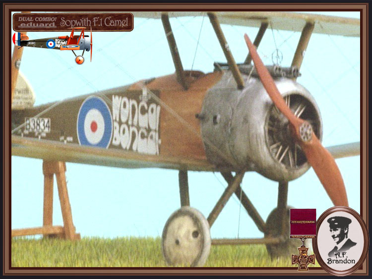
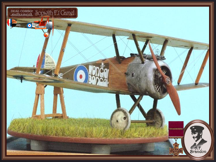
Wonga Bonga
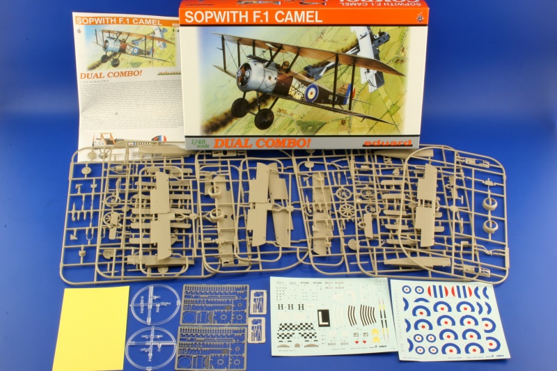
This build will be aimed specifically at the Eduard Combo kit #8060. This kit was awaited with high expectations since it was first mentioned by Eduard representatives at the 2000 IPMS Nationals in Dallas Texas. After the first attempt at creating viable drawings they wisely decided to Go back and try it again. Their second set of drawings became the basis for this kit. The detail is all that we have come to expect of Eduards current production standards. Suffice it to say out of a possible 10 I would give it a 9.5. This is a great kit! The Sopwith model kits always require a little more effort than most other WW1 single seat fighters. With the Sopwith kits notably you will have a top wing that should look like it comes in 3 sections. Doubled RAF wire rigging at half of the locations between the wings and extensively more rigging on the Empennage (tail unit.) Comparatively the Nieuport 17 is much easier to rig than the Camel. Begin with basic clean up and pre-drill all strut locator and rigging holes. Note as you remove parts from the trees for painting or use, try using a flex file to rid your self of any unsightly mold seams. I will also use a flex file to scuff up any potential union joints as this gives the glue surfaces a little stronger bite. PP= plastic part, PE =photoetch, RP = resin.
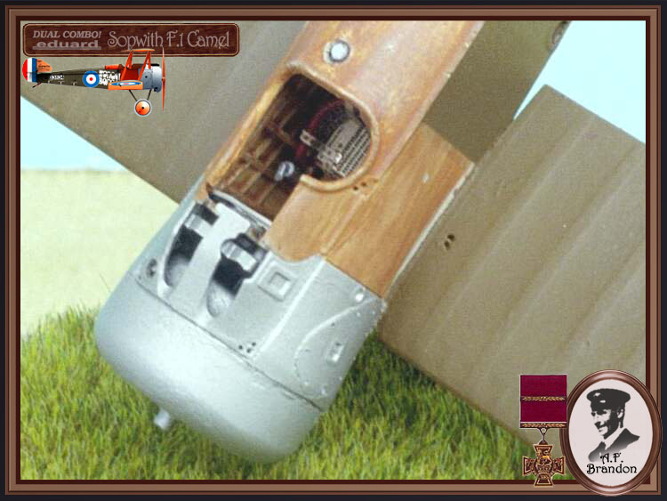
Step 1.) Shows the pilots right fuselage side ( PP A 2) interior and adds some structures ( B 12 & 17.) You can use a linen colour base for the wood and fabric areas. Then stain the wood ribs and ply with the Testors brown #1166. You may also want to thin out the interior face areas (in both fuselage halves ( PP A 1 & 2) where the control cables will enter the fuselage. This will show a scale thickness for fabric. Also you may want to thin out the forward edge to the fuselage cowling area as this area is to match the wing vent for the exhaust and if left unattended it creates an edge that doesnt look scale. (IPMS Judges will use this to disqualify an entry.)
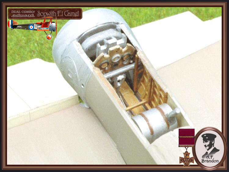
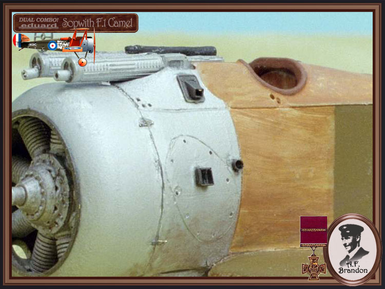
Step 2.) Begins with the assembly of the Clerget type 9B rotary engine. Add the sparkplug leads (PE 39) to the rear of the basic engine (PP B 23.) You can substitute the plastic pushrods on the face plate covers ( PP B 15 & 22 )with brass rod for better scale effect. Or use the kit metal pushrods (PE 13 & 14.) Also, the engine support shaft ( PP B 16) is glued into the rear of the rotary then passes through the firewall and a simple retainer ( PP B 21) is provided to glue to the shaft end. Im not too concerned with having my rotaries free floating or able to turn. For those of you that see this as a viable option try this; Make sure the shaft will pass completely through the retainer. That is the hole for the retainer should go completely through but dont add it yet. Insert the motor/shaft assembly part way through the firewall. Add a very small amount of petroleum jelly to the shaft between the firewall and the back of the rotary. Next completely insert the shaft. On the rear face of the firewall next to the shaft apply another small amount of petroleum jelly. Finally add the retainer and then apply a small amount of thin consistency cyano- glue to the tip of the exposed shaft tip with the retainer in place. The left and right wings of the firewall vent (PP B 30 & 37.) Next mount the oil tank ( PP C 7.) Also firewall wing ( PP B 30) will need a little more blending to the firewall after its attachment. The plastic is soft and easy to work with.
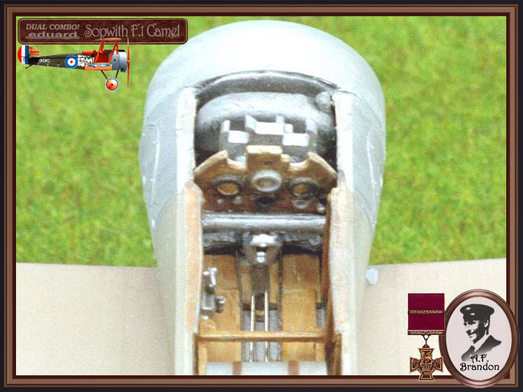
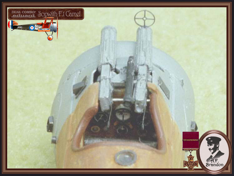
The instrument panel ( PP C 11) is detailed well and references can be found in the Sopwith Camel Datafile #26 on page 20 to their identities. They are top center, manufacturers nameplate, middle center , compass and inclinometer, center left Rev counter (tachometer), right center speedometer, far left bottom leading magneto, next to that is the trailing magneto, center bottom is the altimeter, then at right is the watch, and at far right on the bottom is air pressure gauge and relief valve. The only thing you might want to add is the pulsometer at the panels far lower left corner. The instrument panel ( PP C 11) face itself can be painted to represent Copal varnished wood.. Again I use Testors brown 1166. This is a small bottled flat that when thinned and applied as a wash stains well. (Hint: The slightly stiffer the bristles on your brush the better the wood grain effect you can achieve, just dont scrub the base coat too hard.)
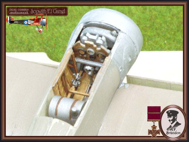
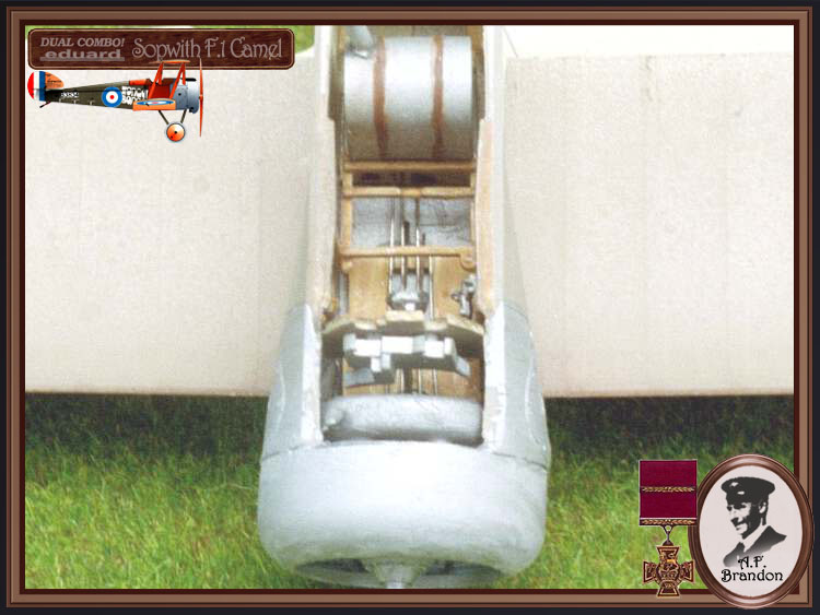
The ammunition box and empty link chutes ( PP C 8) attaches directly to the back of C 11. The rear machine gun brace ( PP B 4) has a locator slot in the face of C 11. I chose to replace this piece with bent metal rod. Check your references. The carburetor intake pipes ( PP B 11) also has a mounting slot in the face of C 11. The rudder bar ( PP B 28) attaches to the base support of C 11. Later you will need to add fine wire to represent the rudder control cables. Next you assemble the hand fuel pump ( PP B 24) , seat ( PP B 38) or (PP B 27 & 36, PE 34 & 36 ) and fuel tank (PP A 5, 13 & B 13) to their cradle/support frame ( PP B 5.) In the scrap view for the fuel mixture control mechanism ( PP B 32) should have a linkage scratch built for the throttle quadrant ( PP B 35.) Note here if your thinking about adding the usual fuel lines and accessories small gauge solder is usually a good choice of materials. It bends easily, takes cyano-glue well and its the right colour.
Step 3.) Adds details to the seat and fuel tank assembles by attaching the Eduard pre-painted metal etch harness (PE 1-4) then unites engines, firewall, instrument panel, seat, fuel tank and fuselage sides. Dont forget to add some representative cable/ wire for the controls an interior structure bracings. Blackened brass wire is a good choice for this use. I also added a blackened brass wire to the tail skid ( PP B 3) for better support.
Step 4.) Is the lower wing (PP D 1), ailerons (PP A 7 & 11), cockpit floor and control column assembly and why Eduard gave us ten ailerons is because of the way they were molded the first time. It might have led to the wrong ailerons being attached in the wrong directions.
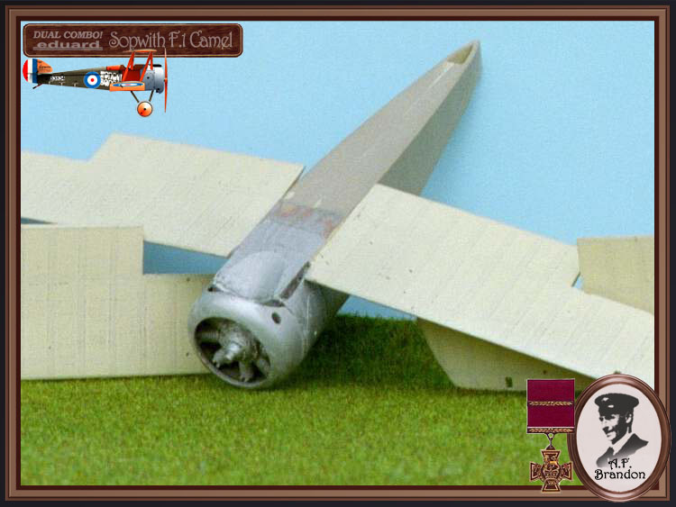
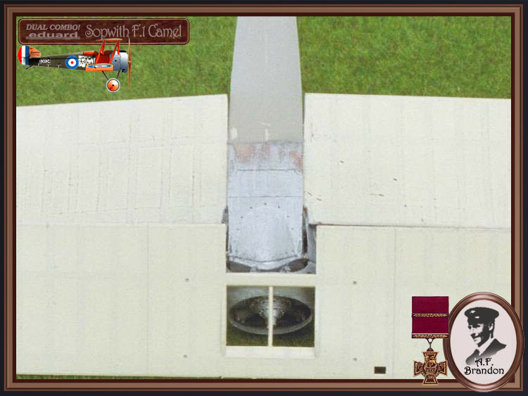
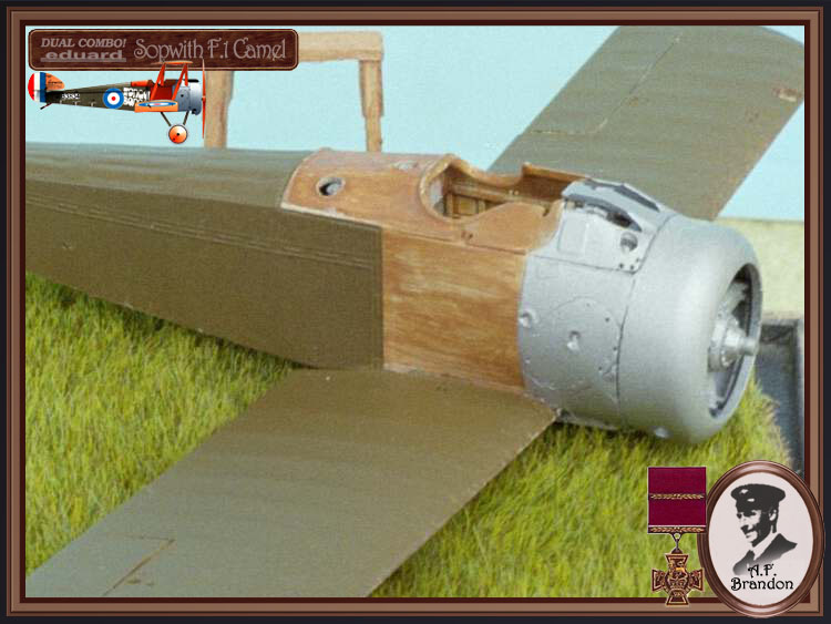
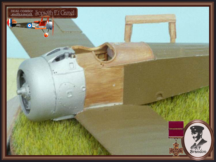
Step 5.) Is the emergency / auxiliary fuel tank (PP B 10 & PE 9 ) application to the cockpit turtle deck and gun cowling ( PP C 2 or 7.) The empty shell ejector chute ( PP B 34) is represented by a plastic stub to be added here. The photoetch (PE 20 7 24 ) sets are far more intricate. There is also a choice of two cowlings. One for a Clerget type rotary (PP C 9) with a small vent and one for the LeRhône type rotary (PP B 10) with out any vent. In scale drawings the Clerget adds about 1 3/4" to the overall length of the standard F.1 type. Later many of the LeRhône cowlings had additional vents added to their 4 and 5 Oclock positions due to the exhaust valve opening later in the cycle than the Clerget that had the single vent at the 7 Oclock position. Check your references. The instructions try to simplify the concern and show C 10 as one you can modify to a Clerget type if you drill your own hole. Also, the Clerget cowling fillet ( B 6) doesnt fit well with out some sanding of its mating surfaces for the Clerget cowling (PP C 9.)
Step 6.) Unites fuselage, lower wing and engine cowling assemblies, horizontal (PP A 15) and vertical (PP A 10) stabilizers and gun breeches (A 8 X 2 & PE 29 X 2.) I drilled holes in the breeches to accept brass pins that will also attach to the gun jackets ( PP A 14 X 2) in the next step. As a side note I usually have to trim down the inner lip of the fuselage halves that receive the engine firewall. Otherwise I have a raised edge that juts out from the pilots left side.
Step 7.) Attaches the Vickers machine gun vented jackets ( PP A 14 X 2.) I painted the gun assemblies with a base coat of aluminum then add a wash of black that darkens the over all look of the pieces. Vickers machine guns were bare metal but the finish was not bright metal. This also makes a great contrast to the cowling if your going with a polish cowling type. There are some photoetch detail parts that apply to specific aircraft profiles in the step along with some nice general details that just enhance the forward side cowlings.
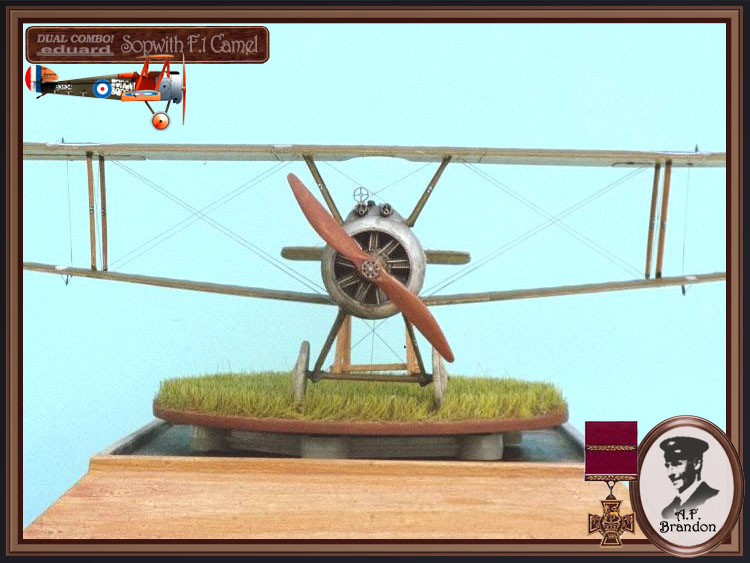
Step 8.) To mount the top wing (PP D 1 or 2) try using a temporary jig of childrens Lego blocks. I would add the outer struts ( PP B 9 X 2 & 19 X 2) first and get the wing plumb then go back and test fit the cabane struts ( PP C 3 - 6) to keep everything lined up. For more strength in the attachments of the interplane struts you can use brass wire or rod inserted into pre-drilled holes in the struts. The exposed ends of the wire can be inserted into the drilled out locator holes. Dont force a strut to go in place as it can throw the wing alignment off greatly. The scrap view shows the Rotherham pump located on the rear starboard cabane strut ( PP C 6.) Check your references as this was variously seen on the forward leg cabane and the forward landing gear legs as well. (See Datafile #26, page 28.)
Step 9.) Continues this placement for the Rotherham pump concerning the various profiles. Next is the landing gear ( B 2, 18 & 20), wheels ( PP C 8 X 2 or PP C 26 X 2) rudder (PP A 9) and elevator (PP A 3) assembly. The landing gear ( PP C 18 & 20) items represents the types that had wood fairings over their steel tube structure. Some airframes simply had the streamlined steel tubing. Next here we have the assembly for the 20 lbs Cooper Bombs ( RP 5 X 4, PE 1 X 16, PE 2 X 4.) Often these were painted a cream or light sand colour. Their nose caps were coloured and in some cases they had coloured rings in addition to the coloured nose caps. The cradle or bomb rack (PE 39 & PE 3 X 4) assembles easily. The reinforcement patches (PE 4) serves as a guide for pilot holes for the landing gear rigging.
Step 10.) Discusses the application of more photoetch on the tail unit and wing tips.
Step 11.) Shows the under surface rigging patterns.
Step 12.) Shows the upper surface rigging patterns and the propeller (A 4) attachment. Several types of propellers were employed on F.1 types. Theyre presence evidently did not indicate with engine type that was installed in a given airframe. Most of these British propellers had a coating of red-brown shellac and the wood grain was not apparent. Check your references. Add your own windscreen.
Decals
Eduard only gives you one set of decals from the Profi-Pack kit. One concern is that they have not included two sets of instrument faces. In fact, some of the other decals are a bit skimpy too - you can not choose any two subjects to build - there aren't enough shared decals. Your going to have to get creative. So it's not really a true "Combo" in that sense. The cockades or roundels in the review kit are a bit off center.
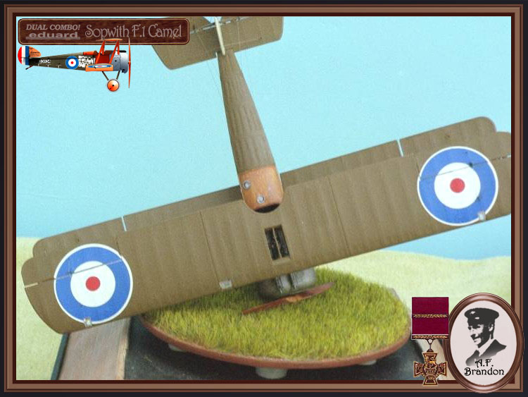
A. Sopwith Camel F.1 B3834 was flown by Flt. Lt. A. F. Brandon of the Manston War Flight at RNAS Manston War School in August 1917. Wonga - Bonga was the phrase used to describe the sounds made by the engines on a Gotha Bomber. Manston started its aviation days as a Royal Naval Station in 1916, with a base at Westgate Bay for seaplanes. The early airfield was on the area now occupied by the passenger terminal. By 1917 Manston airfield had grown to include four underground hangars, its own railway line to Birchington, a power station to generate electricity, barracks for 3,000 men and even an indoor swimming pool. Using this machine Flt. Lt. Brandon helped destroy a Gotha in flames on 22 August 1917. Wonga - Bonga was damaged with a bullet in #6 cylinder, but landed safely.
B. Sopwith Camel F.1 B7296 was crashed by 2/Lt. G. S. Hodson of B flight of 73 Sqdn RFC in France 2 February 1918 (Not 1917.) Rebuilt and fitted with a Clerget 9Bf 140hp rotary. Sent to 208 RAF and crashed on 16 April 1918. Repaired and sent to 51 TDS by 4 November 1918.
C. Sopwith Camel F.1 was flown by Lt. Hollington of 37 Home Defense Sdqn RAF in August 1918.
D. Sopwith Camel F.1 F6022 was the rebuilt airframe from D1813. flown by Captain R. Sykes of 201 Sqdn RAF in France during October 1918. It was sent to 203 RAF by 23 January 1919.
E. Sopwith Camel F.1 B6212 with a Bentley BR. 1 150hp rotary was flown by Flt. Sub-Lt. W.A. Moyle of Sea plane Defense Squadron at St. Pol France in December 1917. This unit became 13N Sqdn RNAS by 15 January 1918. It was damaged on 19 February 1918 when flown by Flt. Sub-Lt. W. J. Mackenzie. Then repaired and sent to 203 RAF by 10 April 1918 where it was flown by an American, 1/Lt. W. W. Goodlow. Last recorded as being at Farnborough 30 June 1918.
F. Sopwith Camel F.1 D3332 was flown by an American serving with the British, Flt. Cmdr O.C. Boots Le Boutillier of 9N until 24 March 1918, when it was crashed. Repaired it was sent to 204 RAF until 2 August 1918 where it was sent to 210 RAF where after several pilots it was assigned to Captain A. W. Carter. The white dumbbell seen on the profile was not adopted by 210 RAF as a unit marking until November 1918.
G. Sopwith Camel F.1 B6313 was flown by Major W.G. Barker while he was assigned to 28 Sqdn and it had been with this unit since 24 Sept. 1917. His first victory on this machine came on 20 October 1917. He continued to us this aircraft after 28 RFC arrived in Italy. Then as CO of 139 Sqdn RAF in Italy during June 1918. This bird had a lengthy war service and was repainted several times.
H. Sopwith Camel F.1 B6313 was flown by Major W.G. Barker as CO of 139 Sqdn RAF in Italy during September 1918. It was dismantled on 2 October 1918. This bird had a lengthy war service and was repainted several times.
References
Barker & 139 Sqdn I.E.F. by R.C. Johnson, IPMS Rocky Mtns Pp.8-9, May 1996.
Colour Profiles of WWI Combat Planes by Apostolo & Bignozzi, Crescent pub. Pp.33-40, 1974.
Four Aces by Doris Reeves, IPMS Sounders-Erhart Pp.126-7 Circa 1972.
General Arrangement Drawings of the F.1 & 2F.1 (printed in 1/48 Scale) by W.R.Titus Cross & Cockade USA , Vol.7 #1, Pp.81-92, 1966.
Sopwith Camel, PAM News Intl. Pp641-646, February 1979.
Sopwith Camel by J.M.Bruce, Windsock Datafile 26, Albatros Publications, 1991.
Sopwith Camel Aces of World War I by Franks, Osprey aircraft of the aces #52, 2003.
Sopwith Camel - King of Combat, by C. Bowyer, Aston Pub. Ltd. 1988.
Sopwith Fighters by J.M. Bruce, Vintage Warbirds #3, Arms & Armor Press, 1986.
The Legendary Sopwith F.1 Camel by Ray Rimell, Scale Models Pp.509-511, October 1978.
The Camel Drivers by Otis Lowell Reed George Roland, Schiffer Books, 2005.
The Sopwith Camel F.1 by J.M.Bruce Profile #31, Profile Publications 1965.
Comments
Eduard has repackaged a good kit using minimal investments in additional artwork. The up-side for them is stock reduction with more profit. The average modeler gets two Camel kits for a very reasonable price. Everybodys a winner. That is what we can expect from them in the next few years. Yet if Eduard is listening maybe we could get some colourful flight instructor markings in a future issue? Also co-operation between a model manufacturer and a decal manufacturer would just be the next step in bringing the average modeler everything they need in one box.
SUMMARY
Stephen Lawson builds Eduard's Sopwith Camel and includes detailed construction notes and comprehensive references to aid modellers tackling this impressive 1/48 scale kit.
Our Thanks to Eduard! This item was provided by them for the purpose of having it reviewed on this KitMaker Network site. If you would like your kit, book, or product reviewed, please contact us.
About Stephen T. Lawson (JackFlash) FROM: COLORADO, UNITED STATES
I was building Off topic jet age kits at the age of 7. I remember building my first WWI kit way back in 1964-5 at the age of 8-9. Hundreds of 1/72 scale Revell and Airfix kits later my eyes started to change and I wanted to do more detail. With the advent of DML / Dragon and Eduard I sold off my ...
Thanks Rowan;
Its always a pleasure to be here. Again I would like to thank our own Jean-Luc for the framed borders and design for the images used in concert with the text. Also let me thank the membership for their staunch support of my works. For some banter bout the beginnings see;
Click here.
Model On!


Comments