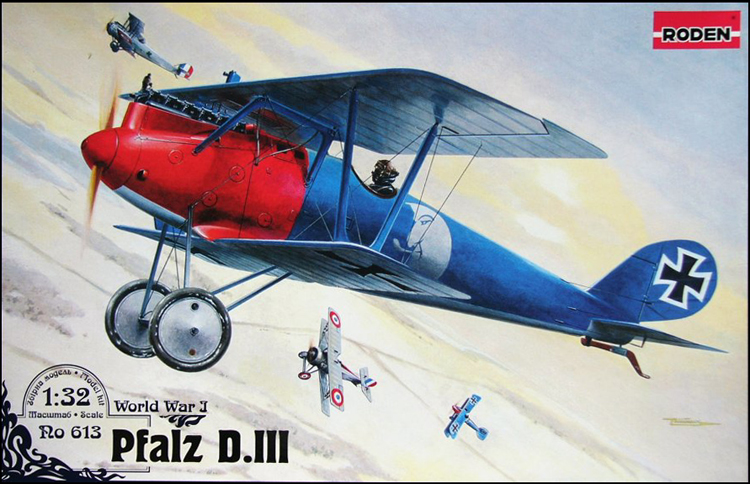
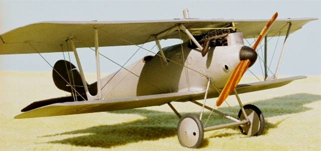
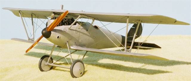
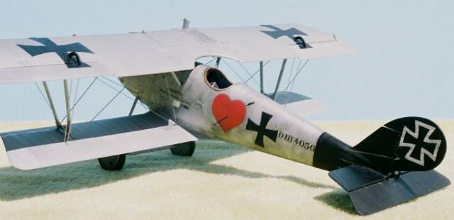
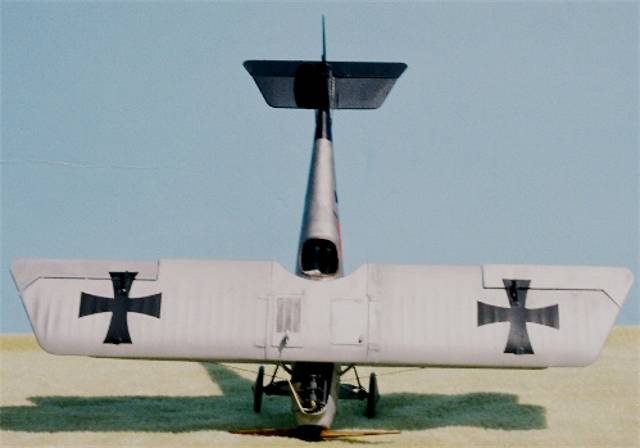
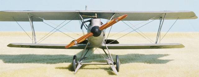
The shark-like profile of the Pfalz D.III appeared on the Western Front in late summer / early autumn 1917. Manufactured by the Pfalz Werke in Bavaria the first examples of the early production types were evidently saddled with the obsolete Mercedes D.III 170hp inline six. Conversely the Albatros Werke fighters had been using the Mercedes D.IIIa 170hp motor since the beginning of 1917 and were now having their D.Va types installed with a D IIIaü 180hp. Several concerns arose as the Pfalz D.III began its service life. First, the guns could not be accessed in-flight to clear jambs as they were buried beneath the forward turtle deck ahead of the cockpit and the access panels were impractical to remove in-flight to clear stoppages. Second, the tail surface was minimal in area for operational use. Thirdly, as mentioned previously the type was underpowered with its Mercedes D IIIa 170hp. Finally greenwood or woods that had not been fully cured were used in the Pfalz D.III manufacture. After some machines arrived at the front it was noticed in the Jasta 20 & 64w field reports say that the tail unit would develop a definite twist to the left or right. This has been directly related to the progressively poor handling qualities of the Pfalz D.IIIa &IIIa.
Kit History
For years the only plastic kit of the Pfalz D.III / IIIa was the old Aurora 1/48 kit of the late 1950's. In the sixties there was the Renwal Aero-skin 1/72 injected kit. In the seventies it was a vacuform kit from Warbirds in 1/72. In the eighties it was the 1/72 Meikraft slush mold injected kit. Then the nineties saw a limited 1/24 release and Eduard finally releasing their 1/48 scale kit. As early as 1998 you couldnt throw a paint tin in a hobby shop without hitting some author doing a build up review of the 1/48 Bird of Prey for a magazine, club newsletter or internet posting. Now as interest in WWI aviation is rising so are the scales in which people are building. Roden is known for highly detailed tight fitting kits and it was no real surprise to most WWI aviation modeling fans that Roden has just released their version of this famous machine. This is the review will focus on the all plastic Trojan horse Rodens 1/32 kit #613
The Build
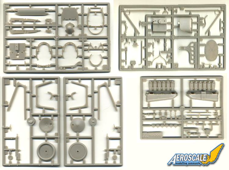
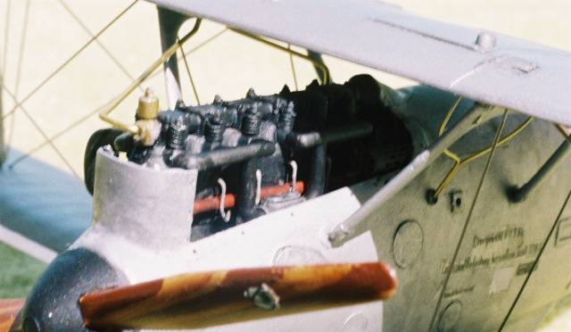
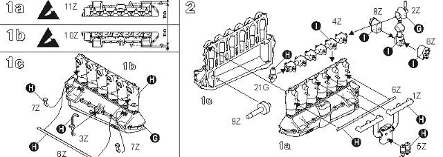
Step 1a-b.) Begins with modifying the supports on the kit engine halves (10 & 11 Z.) They recommend cutting down their tips by 1mm each. Because of the fuselages high collar cowling around the cylinders not much of this fine little engine is seen. The Pfalz D.III types began with the Mercedes 175hp D.IIIa variation and were generally known by the company as type F-1466.
Step 1c.) The upper portions of the original aircraft engine cylinders are covered by water jackets these are the color of black/blued gun metal. This kit shows the water fillers / vent caps ( 7 Z X 2 ), oil cycling tube ( 3 Z ) and the sparkplug support tube ( 6 Z ) for the pilots right side of the engine
Step 2.) Primarily the water pump on the Mercedes (Daimler) D. IIIa is located directly behind the cylinders on the tower ( 2 Z ) and check your references for routing of the external plumbing. I added fine wire painted ( black or white) to simulate spark plug wires. The air pump (24 G not 21) is added to the front. The twin spark magnetos ( 8 Z X 2) are attached to the base of the tower ( 2 Z ). The other sparkplug support tube ( 6 Z ) the carburetor support with manifolds (1 Z ) and twin carburetors (5 Z ). The fit of the engine supports and the engine will be tight. I had to carve down the back of the twin carburetors (5 Z ) the fit was so tight. The front of the crankshaft / propeller spindle ( 1 G , not 9 Z ) is to be trapped between the engine halves ( 10 & 11 Z ) with a small bit of petroleum jelly or graphite for lubrication. It wont hurt to apply a bit of sanding film to the rim of the retainer of this part.
The real engine was introduced around 1 Feb 1917 for the Albatros D.III. It used flat topped pistons and can be recognized by
Rocker Arm Box Position ( 4 Z )-- the overhead cam rocker arms come out of the middle of the camshaft bearing boxes.
Water Pump Location ( 2 Z )-- the water pump is above the crankshaft on the jackshaft that goes from the crankshaft up to the camshaft ( between and above the magnetos
Air Pump (24 G )-- the fuel pressurization air pump is a single cylinder model mounted at the front of the engine on top of the camshaft above and infront of #1 Crankcase Shape -- the crankcase has a smooth, tapering profile from the main body forward to the front main bearing. It is rated at 170hp.
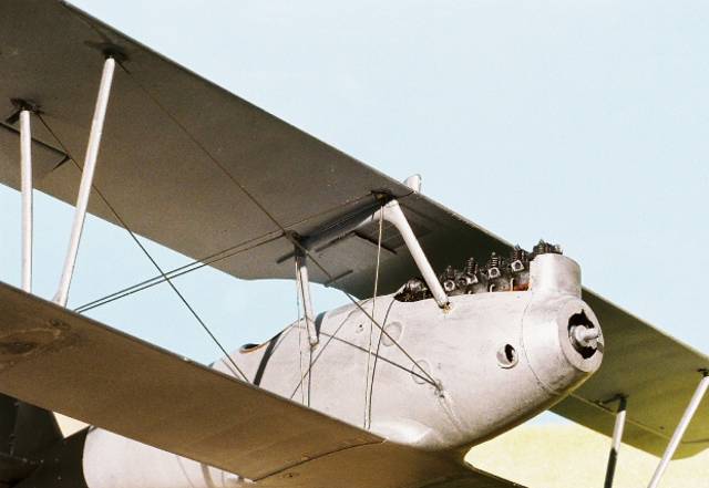
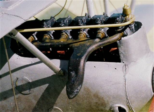
The immediate visual difference in the early Mercedes D.III 160hp / D.IIIa 170hp (F-1466 )and its progeny the D.IIIaü 180hp (1466a) are in the rocker boxes above the cylinder jacket heads. On the early Mercedes D.III and D.IIIa motors the rocker springs ( 4 Z ) are centered on the sides of the rocker box covers. On the D.IIIaü motor the box covers are moved back so the rocker arms and springs are located on the forward leading edge of the same covers. The rest is below the cowling and not readily visible. The Mercedes D.III 160hp was outclassed by 1917. In 1918 the Mercedes D.IIIaü 180hp was the standard engine in the Pfalz D.IIIa, Albatros late built D.V and all D.Va types starting in late 1917 and then the Fokker D.VII through 1918. Many, many Mercedes D. III and IIIa type motors were rebuilt to the D.IIIaü specs at the airparks as the war progressed. That is why some captured examples had motors with the i.d. designation of D.III 160hp cast into their crankcases. This has caused the misconception that the standard 160hp and 170 hp were used in 1918 at a time when they had become obsolete. Often these were referred to as 160hp over-compressed engines.
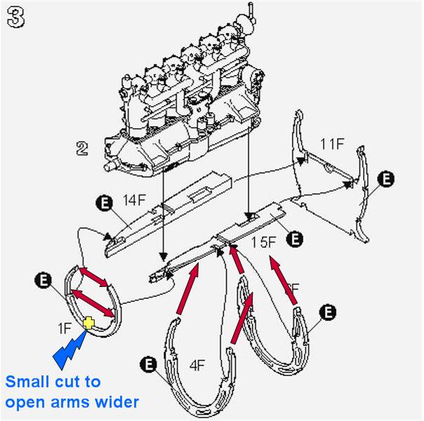
Step 3.) The exact placement of the engine bearer shelves ( 14 & 15 F ) in the fuselage formers (1,4,6 &11) is easy to deal with. Remember that the second former (4 F ) is angled forward at the bottom. Also the third former (6 F ) is angled slightly backward at the bottom. You can add eight R&R model detail nuts & bolts from Grandt Line to represent the motor mount items that would be apparent on the top face of the motor mount flanges. The fuselage formers the shelves come together here is a subassembly. Note that the first former (1 F ) needs to be opened up by cutting a small notch inside the ring. It is a tight fit. Also, to get the fuselage to close up correctly in step 11, you will have to clip off the decompression handle on the upper Jack Tower ( 2 Z ) of the engine. Check your references. On the Albatros D types this was exposed and the handle was usually solid metal. On the Pfalz D. types this decompression bell was shrouded by a shell shaped covering. The handle was wood and unscrewed.
Step 4.)We start with the fuselage former ( 9 F ) at the mid-section of the cockpit. Add the fuel tank pressure, hand pump ( 17 G ) and the auxiliary throttle advance lever. ( 10 G ). Please note the installation of fuselage former 9 F is inclined back about 2 degrees at the top. To the cockpit flooring (8 F ) add cables and a control column lock ( 2 G ) can be added to the control column base ( 14 G ) Note also that the rotating throttle on the control yoke head ( 24 G ) should be on the pilot's left. see the inset image. The machine gun triggers are in the middle of this yoke. Also add the rudder control bar (5 F ). The aileron actuation bar assembly (5 & 25 G ) connect to the bottom of the control column ( 14 G ) under the flooring. In the image here I only have two lines on the lower end of the control column ( 14 G ). To be accurate there should be four.
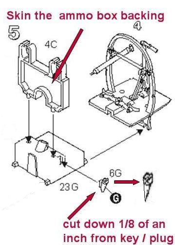
Step 5.) Next the cockpit flooring (8 F ) and the ammunition box ( 4 C )and machine gun braces ( 5 C ) sit on is the top of the main fuel tank ( 6, 23 G ). This brings all of the previous sub assemblies together. Dont be afraid to open up the slots on the fuselage former slightly to accept the fuel tank locator stubs. Also I had to cut down the spout (6 G ) by about 1/8 of an inch to get the assembly to seat well in the fuselage half during a dry fit. If you do not do this it will throw your fuselage out of alignment with your lower wing later.
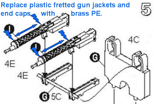
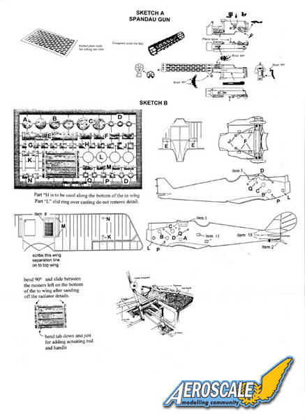
Concerning the twin Spandau Maxim machine gun (4 E X 2 ), the solid plastic cooling jackets cannot be seen once the fuselage is closed up. I replaced the cross bar on the gun trays (5 C ) with a metal rod. and cut down the front gun supports and removed the rear gun supports on the Spandaus.
One minor concern is that to get the left gun completely in place vertically the inner fuselage (1 C ) wall above the breech needs to be thinned or the breech cut down. For those of you thinking about exposing the engine and adding photoetch gun jackets. Do not add them here. Dry fit the jackets you want to use and then wait until the fuselage is closed up. This will minimize any possible damage. Just make sure they slip on and off easily.
Also, confirmed by photographic evidence that none of the Pfalz D.III or D.IIIa types had a spade shaped cocking handle. These are popular items that some modelers like to add. The Pfalz fighters used T shaped handles ( but there should be two of these.) in the cockpit leading from the cocking levers on the right side of the gun breeches and worked via a linkage system. For further detail the left side of the left gun breach add an auxiliary throttle push lever These items came as O ring or T handles.
Step 6.) Rudder and the control horn assembly.
Step 7.) Horizontal tail unit and the control horn assembly.
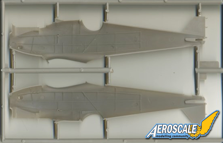
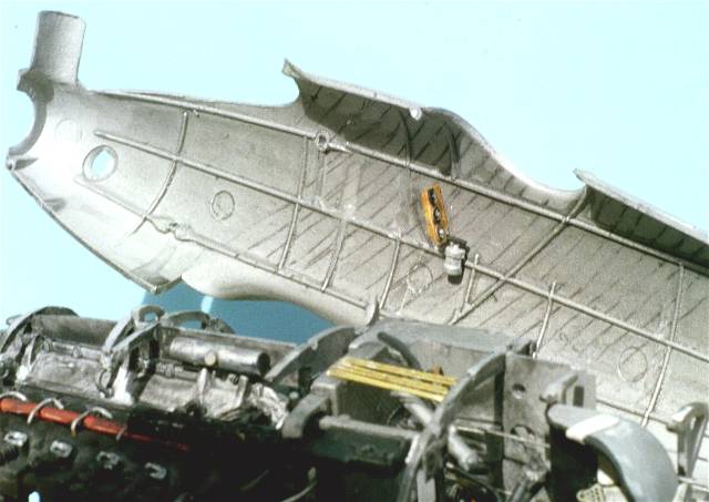
Step 8.) For the right fuselage half interior, make it easy on yourself, begin this project by familiarizing the areas for the internal structure of the fuselage halves ( 2 C ) and pre-drilling all rigging holes. I went further and scribed parallel lines on the inside the cockpit walls to represent the wood lath / strips that went into the make-up of the Pfalz fuselage shell halves. Paint both fuselage halves ( 1 & 2 C ) interiors and the fuselage formers either:
A a dull aluminum or
B. a base color of Polly S dirty white, antique white, French beige or doped linen. This gives you a nice base for the plywood effect that you need to duplicate.
After these are thoroughly dry, spray the painted surfaces with a clear flat. Allow it to dry completely , then if you are doing a varnished wood interior begin with a wash of Testors (#1166) flat (orange) brown enamel always going parallel to the lath edges. Down the length if the fuselage. The resultant streaks will simulate the wood grain. Then dry brush just the frame work with the base colour. The colour variations that you create when doing this makes a great contrast to the inside wood lath. It is known that both methods were popular for sealing the interior shells of the Pfalz single seat fighters. Photographic evidence shows that both methods were used. There are even cases where the fuselage formers were varnished wood and the interior of the fuselage shells were aluminum doped.
I used the kit fuel /air control panel ( 12 F) and mounted it per the original aircraft. The attempt at scratch-building a scale wiring control harness will be fragile but will pay greatly in the end. Add a short section of painted solder leading forward to represent the tube for the water pump greaser (21 G )
Step 9 ) The Bosch starting magneto assembly ( 7, 11 G & 13 F ) is straight forward but note its placement and wiring in step 10.
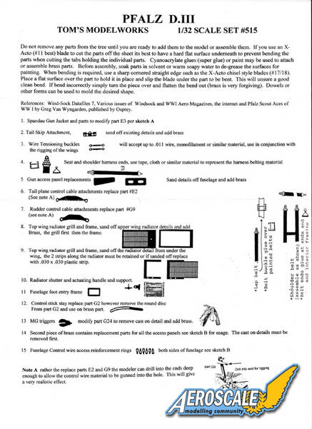
Step 9a) Seat assembly ( 2, 7 F & 20 G ) To do this area justice it is advisable that you construct / manufacture lap and shoulder harnesses. This can be done with common masking tape with buckles cut from sheet plastic. Toms Modelworks sheet has some fine items for buckles and tie-downs.
Step 10.) Add the rear cockpit screen ( 3 G ). The tachometer (15 G ) on the Pfalz D. Types appears to be upright in all cases. On other single seat types they were laid on their sides. For the left side of fuselage former add the starting magneto switch assembly ( 2, 7 F & 20 G ). To be absolutely correct one could add a wire switch to the circular area as there was a key that was attached by a small chain but would reach to the circular instrument. (Much like a key to the ignition of a modern car.) The Bosch starting magneto should have a bundle of ignition wires with a faded red insulation cover leading from the lower area of along the fuselage interior toward the forward area of the engine compartment. I added an oil tank from a cylindrical section for sprue with a sprue slice as a cap. This is located on the pilot's right side of the engine compartment back on the rear portion of the engine bearer shelf. Here is a list of "other items that I added to the cockpit.
a. tachometer gauge face and bezel.
b. main fuel tank gauge face.
c. air pump gauge. / "Manometer."
d. 2 lap and 2 shoulder harness / webings and 4 PE buckles.
e. floor mounted compass gauge face and bezel
f. 2 foot stirrups to the rudder bar.
g. Synchronizer cables from engine to gun breaches.
h. 2 Bowden cables from control column to the guns.
i. 2 rudder , 4 elevator cables.
j. brass conduit pipes for the electrical wiring from the instrument cluster on the pilot's right.
Step 11.) Now glue the fuselage halves (1 & 2 C ) together and allow to dry. To get the fuselage to close up you will have to clip off the decompression handle on the upper rear tower of the engine. This was removable anyway on the real machine ( it unscrewed.)
Then erase all union seams. Add the rudder and horizontal tail unit assemblies. Careful sanding helps the horizontal tail unit ( 3 C ) fit properly. I used gap filling super glue (semi gelatin) to fill joint seams between all plastic parts joined to the fuselage. Note that canting control surfaces tends to give the piece a more natural look seen in period images of the real aircraft. The kit rigging control horns ( 9 G & 2 E X 2 ) can be used per the instructions. Add the lower wing ( 1 A ) at this time.
Concerning the lower wing ( 1 A ) attachment. I had to trim about 1/16 of an inch from the trailing end and had only minor sanding to finish. The fit is near perfect. BUT you may remember I had to cut down the fuel spout and the engine carburetors . Had I left these items alone I would have run into some serious fit problems with the lower wing and fuselage at this point.
Remembering that the top wing came in three pieces on the original, we must now deal with the minor leading edge issue. The leading edge of the top ( 2 A) wing from about the radiator over to the pilot's right side of the top wing has a minor flaw. Possibly because of the single wing molding method. Plunging it into warm water and gently bending the edge into place fixes it completely. I have had to do this even on 1/48 scale kits so its not a big deal.
Step 12.) Top wing ( 2 A) details show the aileron control actuators ( 6 E ) and the radiator filler tower (13 G ). In most cases a shutter system was employed on the D.III and D.IIIa airframes. This was to either dissipate or retain heat in the radiator. Depending on the weather conditions during a given patrol or flight. I decided to erase the molded in detail except for the rails the shutter is attached to and use the Tom's brass. In truth you only gain a bit of depth but I like it.
Step 13.) Brings the fuselage and wings together. It should be noted that most circular engine access panels need to be flush to the surface but not completely erased. For the top wing( (2 A ) I generally paint the undersurface of the top wing and the upper surface of the lower wing (1 A ) at this point before assembly and rigging. It depends on what you are comfortable with. I chose also to pin the wings and struts together. This is done by drilling corresponding holes then insert and glue brass pins in the hole sockets to unify wings and struts. Note if the cabane ( 9 E X 2 ) or wing struts ( 1 E X 2 ) ends enter the wing at an angle drill your insert holes accordingly.
Step 14.) Assembles with water / coolant plumbing (12, 16 & 19 G ) and engine exhaust manifold (4 G ). The common exhaust is seen here but there were several manufacturers. There was even an early version where the exhaust horn was ahead of the #1 cylinder.
Step 15.) Is the installation of the fuel lines( 8 G ) for the reserve / gravity tank.
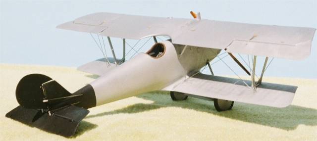
Step 16 .) The weakest part of a Vee strut landing gear assembly in plastic is the side to side twist. In many kits this usually causes the plastic gear legs to eventually dislocate or break. But with the Roden kit I use the kit landing gear legs (18, 26 G ) and the exposed axle ends (16 F ) with the appropriate diameter blackened brass rod. I use upholstery thread to wrap around the lower legs of the landing gear with the axle, to simulate the bungee shock chords. This looks like the original and actually secures the axle in place with one drop of cyanoacrylate glue. Finish any rigging now.
Step 17.) Add the tail skid ( 3 F ) . I personally like scratch- building my kit propellers from light and dark woods. I have also learned to paint the laminations with convincing effect. Most of the Pfalz fighters were equipped with the light and dark laminated propellers. Carefully check the aircraft profile your modeling to choose the right propeller. Roden offers two possibilities with this kit. The company determined the paddle profile of the propeller (it was their trade mark) while the engine application determined its pitch and length. So all three profiles could be seen on the D.III, but with the same pitch because of the factorys installation of the Mercedes D IIIa 170hp motor. Now I modify and add the tail skid ( 3 F ) After the final clear coat of your model dries thoroughly attach your windscreen with white glue.
Kit Decals
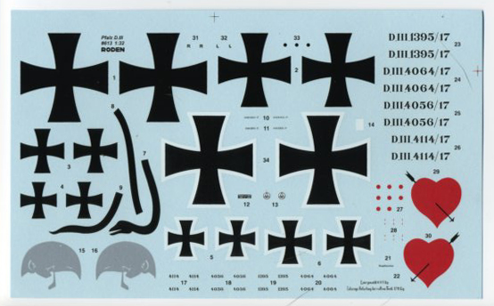
These decals are very easy to work with and seem very resilient. With care repositioning or adjustments are not a problem. I did use Sol & set solutions and cut very close to the colored areas. If you do so, care must be taken at this point to use a SHARP razor knife blade. ( Xacto #11). The removal of the clear border helps the decals look like they are painted on. For the average modeler without sol or set you may want to use a little diluted white (poly) school glue (50% water -50% glue), for better decal adhesion. Before applying water to the decals you may find that cutting the smallest bits (even with a sharp knife) actually lifts the decal from the paper. Yet, they do seem to stick well with either the sol & set or the diluted glue.
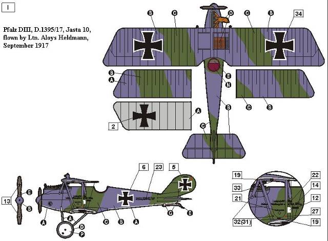
I. Pfalz DIII, D.1395/17, Jasta 10 was flown by Ltn. Aloys Heldmann during September 1917. A small number of the earliest production airframes (not all) were done in a two toned spray camouflage from the factory. This machine is particularly well studied as there were a series of photographs taken of its pilot beside the machine. The aircraft is clean that is without any unit or personal markings at this point.
II. Pfalz DIII, serial unknown, Jasta 10, flown by Ltn. Hans Klein, November 1917. Most of the machines in Jasta 10 were in silbergraü - aluminum doped over all. Several images of this machine exist. One after it performed a ladys landing. This is where the machine flipped over on it back wheels up.
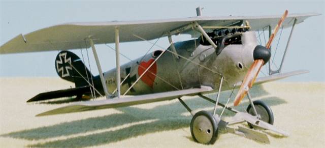
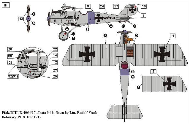
III. Pfalz DIII, D.4064/17, Jasta 34b, flown by Ltn. Rudolf Stark, February 1918. Not 1917. After serving in the 2nd Bavarian Uhlan Regt, he went to the German Air Force. Next to FA(A) 296 on 15 Nov. 1917, and then off to Jstschl. II for fighter training. Joining Jasta 34b on 18 Jan. 1918, he scored five confirmed victories in the spring of 1918. On 24 May, he joined Jasta 77b as acting commander. On 7 June, he was reassigned to Jasta 35b as Staffelführer where he remained until the end of the war.
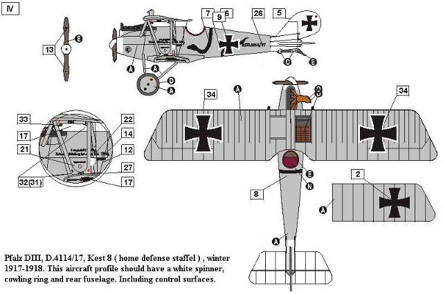
IV. Pfalz DIII, D.4114/17, Kest 8 ( home defense staffel ) , winter 1917-1918. This aircraft profile should have a white spinner, cowling ring and rear fuselage. Including control surfaces. Home defense units were established to protect cities with industries and factories. The white borders on the top wing crosses are doubtful. Probably just plain black crosses.
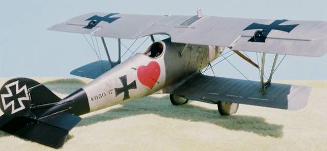
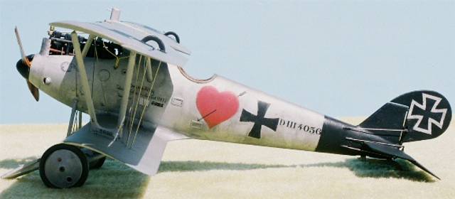
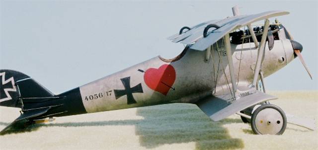
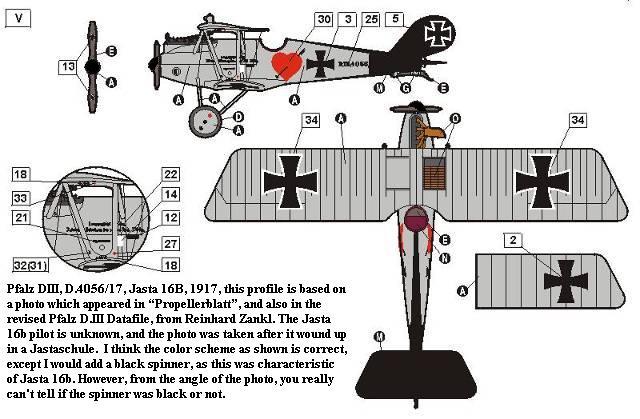
V. Pfalz DIII, D.4056/17, Jasta 16B, 1917, this profile is based on a photo which appeared in Propellerblatt, and also in the revised Pfalz D.III Datafile, from R. Zankl. This pilot is unknown and the photo was taken after it wound up in a Jstschl. The the color scheme as shown is correct, except it may have a black spinner, as this was characteristic of Jasta 16b. But with the angle of the photo, you really can't tell if the spinner was black or not.
VI. Pfalz DIII, serial unknown, Jasta 18, flown by Ltn. Walther F. Kleffel, winter 1917 - 1918. This machine was flown by several different pilots. Most notably by Ltn. Burkhard von Buttlar especially during the time that Jasta 18 & 15 changed identities in early 1918.
Listed References:
Colors by Greg VanWyngarden, Over the Front Journal Vol 2 #4,Pp.371-5, 1987.
Fliegertruppe Nr. 2 by A. E. Ferko, private publishing.
German Army Air Service in WWI by R. Rimell, Osprey Vintage Warbirds #2, 1985.
German Fighter Units June 1917-1918 by A. Imrie, Osprey, Airwar #17,1978.
Pfalz Aircraft of World War I by Jack Herris, Flying Machines Press, 2001.
Pfalz by P. Grosz & E. Krüger, WWI Aero Pub. inc. 1964.
Pfalz D.III by R. Rimell, Datafile WWI a/c Part 1, Windsock, Albatros Pub. Ltd. Pp.20-31, 1990.
Pfalz D.III by P. Gray, Profile Pub. #43, 1965.
Pfalz Scout Aces of World War I by Greg VanWyngarden Osprey pub. #71, 2006.
Pfalz D.III Technical evaluation by Flight Cross & Cockade USA Vol.1 #4, Pp. 29-53,1960.
Pfalz D.III 1370/17 evaluation by Flight Cross & Cockade USA Vol. 2 #3 1961.
Pfalz D.IIIa by P. Grosz, Windsock Datafile #21, Albatros Pub. Ltd. 1989.
Pictorial History of the German Army Air Service by A. Imrie, Ian Allen Pub. 1971.
Scale Model Aircraft in Plastic Card by H. Woodman, Model & Allied Pub., 1975.
Spandau Machine Gun by David Watts, WWI Aero,1998.
World War One in Plastic by Brad Hansen, Great Auk Pub. 1979.
Comments
As I stated the aim of the single kit work up is not to rip apart a kit. The focus here is to explain or answer questions about building the kit. While we as modelers invest our money and have a right to gripe, I feel we owe the model manufacturer a debt. That debt is to help them know what we are looking for.
SUMMARY
Highs: Concerning markings, and modeling subjects, fit, build-ability and accuracy. Roden gets top marks in all categories plus ONE. They listen to our concerns . They are among the few that do.Lows: The modeler just needs to be aware that the fit needs to be checked and re-checked to keep it easy to close the fuselage.Verdict: For an all plastic kit in 1/32 I have to say it builds up great.
Our Thanks to Roden! This item was provided by them for the purpose of having it reviewed on this KitMaker Network site. If you would like your kit, book, or product reviewed, please contact us.
About Stephen T. Lawson (JackFlash) FROM: COLORADO, UNITED STATES
I was building Off topic jet age kits at the age of 7. I remember building my first WWI kit way back in 1964-5 at the age of 8-9. Hundreds of 1/72 scale Revell and Airfix kits later my eyes started to change and I wanted to do more detail. With the advent of DML / Dragon and Eduard I sold off my ...
Thanks Stephen
Thats a proper review by someone who has clearly taken the trouble to learn about the subject matter and then actually built the thing.
Knowing not much about stick and string aviation but liking the shape and the colourful markings, I just scored one on eBay and your review will be very helpful when I tackle it.
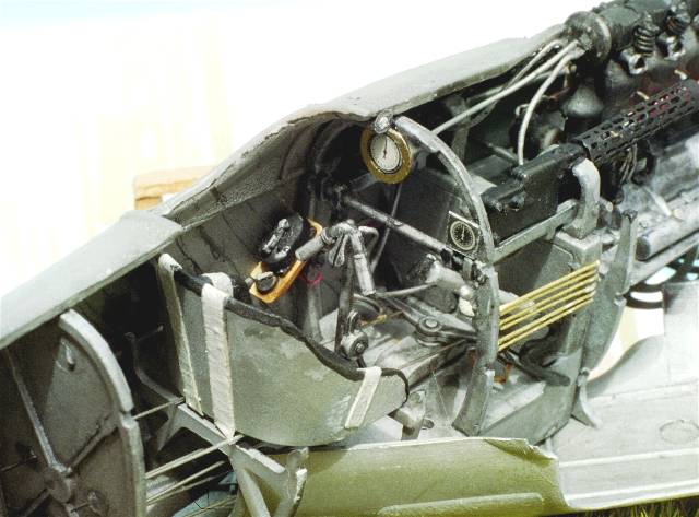
Here is the cockpit interior with some Tom's Modelworks brass, lap & shoulder harbess, Fotocut gauge bezels, sybchronizing cables.
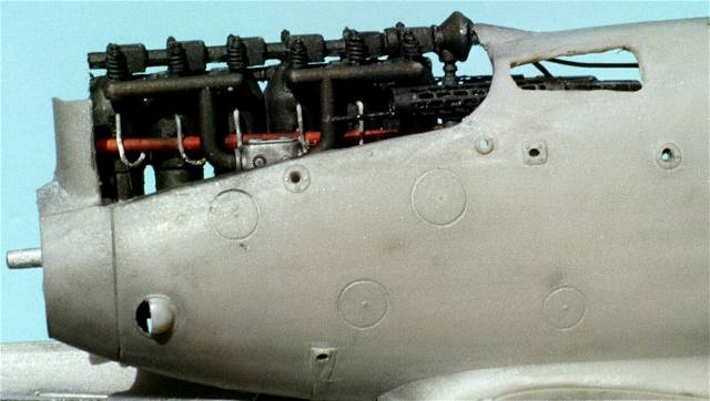
Note the repositioned rocker boxes and the access cut out for the pilot's port / left side Spandau breech. I used a Tom's Modelworks Pfalz D.III brass panel to cover this area.
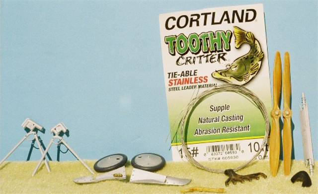
Various pieces in basic colours and the fishing leader line (steel wire wrapped in clear Vinyl).
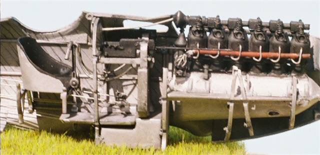
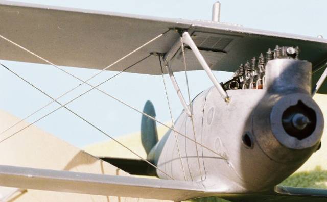
Here is the build almost completed but no decals or aileron acuators yet.
Note the Axial kit propeller has been painted to represent wood laminations.


Comments