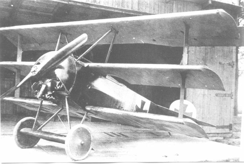
The first victory recorded in a Fokker Triplane was achieved by Rittmeister Manfred von Richthofen when he brought down an RE 8. The crew believed the oncoming machine to be a British Sopwith Triplane. Thus the wolf in sheeps clothing had arrived. Early in the production series, bad construction and the proximity of the top wing to the propeller wash caused in-flight failure. Being withdrawn and then re-emerging in strength in Jan.1918 the Fokker Triplane equipped most of the Jagdstafflen of the 3 Jagdgeschwaders (Fighter Wings) of the German Fliegertruppe during the first half of 1918.
Other companies issues,
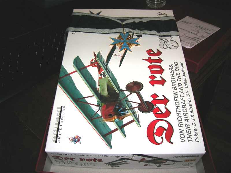
Aurora kit held the reins for years in the 1/48 scale. In 1989 the brave effort of Blue Max gave us a truly more accurate version of the Dr.I. The highly detailed White metal motor was the main draw to many modelers. The Blue Max kit was hindered only by the pinning needed to attach wings and struts securely. Still, to the collector the Blue Max kit is a must have item in any case. Finally, the first effort in the WWI arena for Dragon Models Limited (DML) was its fine production of the Dr.I. Issued in 3 different pilot liveries this kit is the standard to date of the best Fokker Triplane in 1/48 scale. I personally have built 35 of these DML kits since 1992. The later Hong Kong issue is lessened by the poor type of photoetch included for the Spandau machine guns. Now we have Eduards long awaited offering. First released 13 May 2008. There were to initial releases called Der Rote Flieger. The 1136 issue and the 1136X issue. This last Special Red Box edition is what we will look at here. Note some of the parts are for either the F.I pre-production triplanes or the Dr.I main production triplanes.
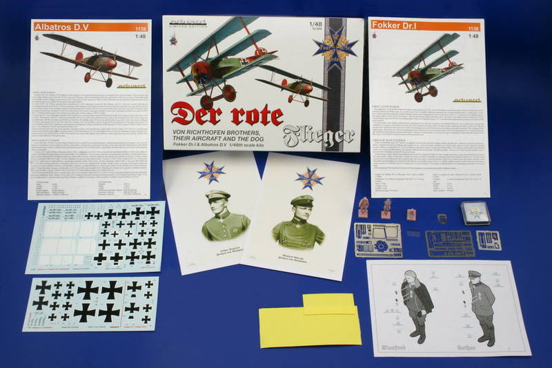
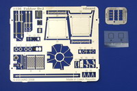
4 sheets of photo-etch
2 decal sheets for 10 marking variants
2 sheets of the canopy mask
Printed portraits of Richthofen brothers
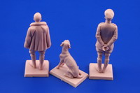
High quality resin figures of Richthofen brothers and their dog
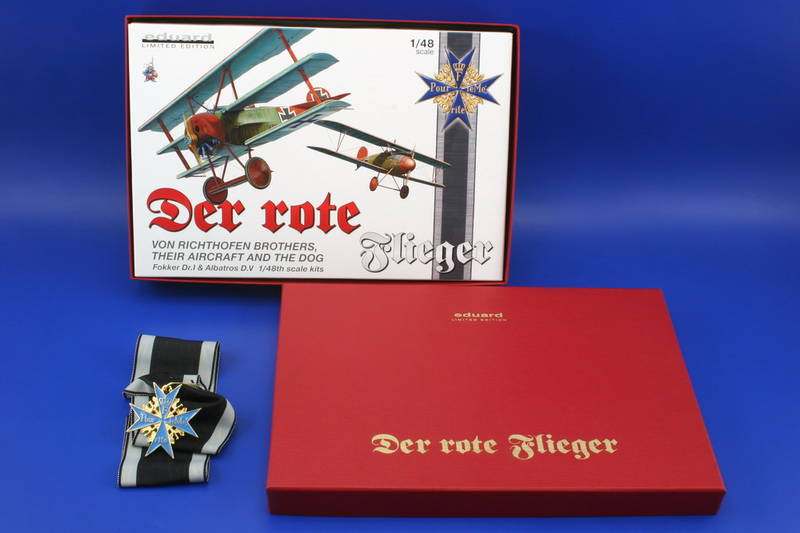
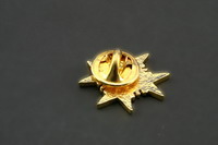
1/3 scale Pour le Mérite pin
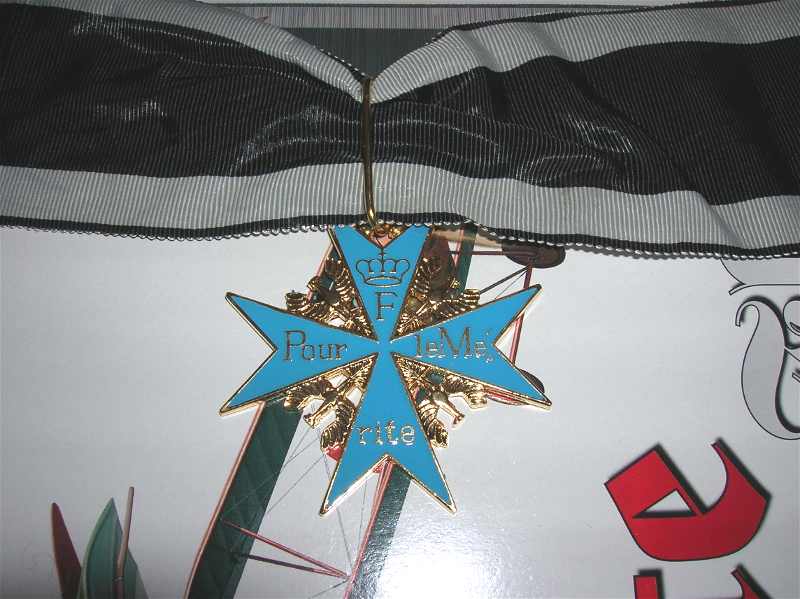
1/1 scale Pour le Mérite badge replica with ribbon
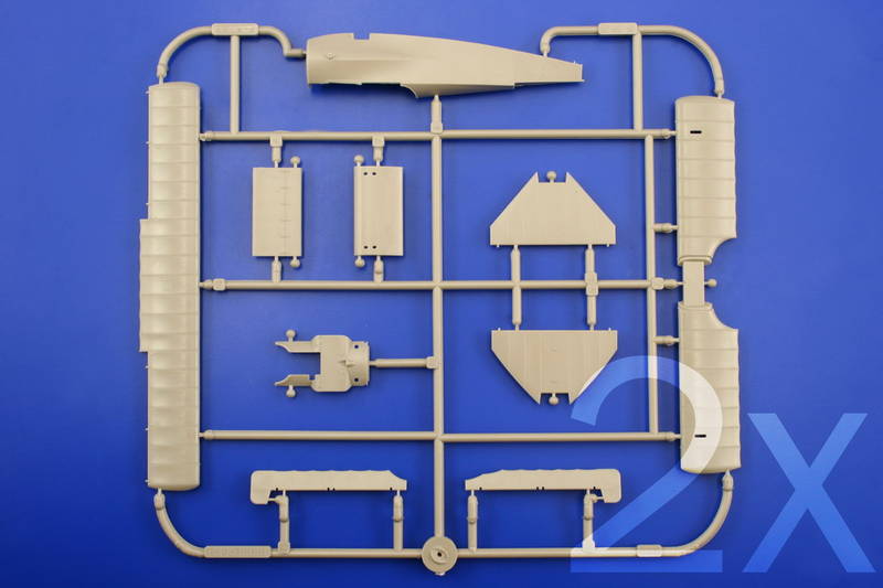
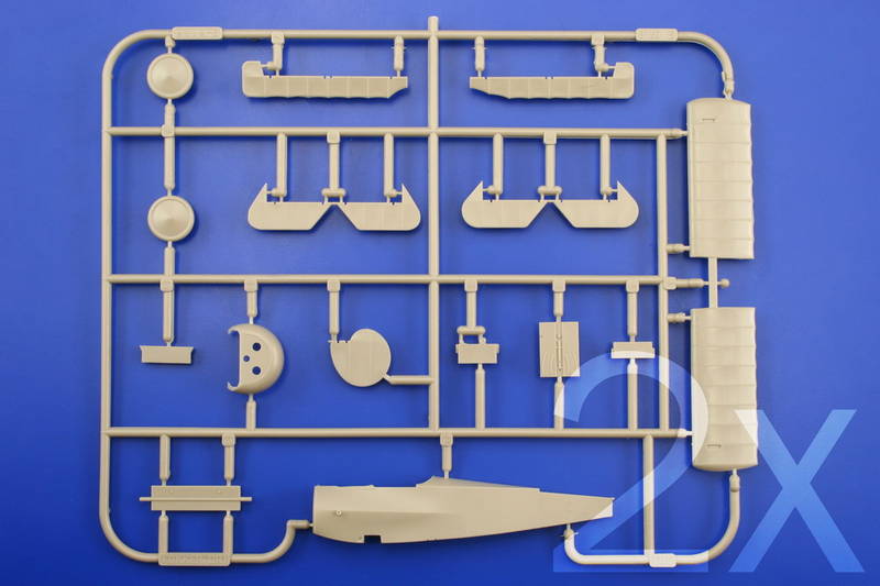
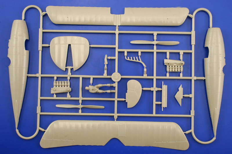
The Fokker F.I & Dr.I kit,
Page 3. Ignore the kit instructions for color applications especially concerning the interior fabric surfaces. The interior wood faces should all be clear varnished on the Dr.I . The only painted portions were the metal fixtures. According to photos of crashed Dr.I types where we see the cockpits opened up to extract the wounded pilot personnel. These photos show that a light grey green or mid to light grey was used on metal surfaces. Instrument backing cup should be mid green or black. The triangle shaped fairings that flare the fuselage sides (PP A 1 & B14 ) and flooring panels ( PP B 5 ) should be varnished wood.
I begin with cleaning the simulated fuselage skeletal structures ( PP C 16 & 19.) Then I add two short sections of brass rod under the flooring that run from on lower longeron to the other. These items can be painted as you add them. I added a small tab of plastic to the lower end of the control column (PP C 29) - use a .080 gauge drill bit to cut into the ends to add the wires going back toward the rear area under the seat. I am not enthused with this piece. Normally I would replace the kit control yoke with a Toms Modelworks or Part of Poland photoetch item. Eduard has not gotten this right with any of their Fokker kits. The lattice (PE 5) is supposed to represent the Bowden cables for the Spandau machine gun triggers. It seems Eduard thought that using PE would give this assembly some strength.
You will have to scratch build the fuel tank air pressure hand pump for the right side of the cockpit. Solder can be used to make the air hose and give it a half loop at the bottom and it should lead forward to the engine area. The pump itself should be bare metal / aluminum and the handle black. The rudder bar stabilizer and forward gun mounts ( PP C 6 ) and the rudder bar ( PP C 40 ) unite to form the basis of the cross members that the ammo box (PP B 6 & PE 22) and empty ammo belt box ( PP B 4) will hang from.
The compass assembly (PP C 26, PE 6,12 & 16) is nicely detailed. Paint the inside of the fuselage halves ( PP A 1 & B 14 ) an off white / linen colour before joining permanently. The plywood fairings are as stated, varnished wood. The three support structures for each of the fairings was metal tubing. At this time add the rigging material of your choice to the cockpit controls.
According to the seat from 425/17 in Canadas Royal Military institute you should add .040 to the underside of the seat (PP C 23.) Use a motor tool cutter to thin the inner face of the back and arm rest of the seat (PP C 23). The back of the aluminum seat ( PP C 23) was evidently covered in unbleached fabric on the inner face and the seat cushion (PP C 13) was the parachute pack. I add a section to the underside of the seat to get the depth and then simulate the parachute pack texture and harness rings on the kit seat itself. The outer face would be aluminum. I will usually replace the seat supports ( PP C 3 X 2 ) with bent brass rod and add a cross brace to rest the front edge of the seat ( PP C 23 ) on. The harness assembly ( PE 1 & 2 X 2 ) are easily pressed in place but add a clear dull coat to the pre-painted faces them first and let dry. Begin with the harness buckles and work out to the other ends. Once shaped the item can be glued into place again starting with the buckles and working outward. The screen / bulkhead ( PP C 12 ) can be painted to represent unbleached / clear doped fabric. The reinforcement edge was leather. The horizontal bar on the screen/bulkhead ( PP C 12 ) is where the back of the seat rests. This was attached with seven pop rivets.
The ammunition box ( PP B 6 ) needs to be notched at its lower corners to match the original item. I will add a small block of styrene to the bottom edge that will be short enough to cause the notch I was speaking of. Check your references. Attach the ammo box ( PP B 6 ) to the framing ( PP C 19) using the notches and locator plugs provided on each item.
Page 4.
The empty ammo belt box (PP B 4) and the rear machine gun support (PP C 39 & PE 11) are added here. Note the scrap view of the fuselage half showing the relative locations when in place. The handle to the air mixture quadrant ( PE 7 ) should be bent in slightly. The pilot should be able to reach this with his left hand and operate it without banging his knuckles. Also the Bosch staring magneto (PE 4) should not be added to this build. The starting magneto is represented by the rounded plate at the pilots left already molded to the fuselage. There is also a small bulk head added to the rear of the fuselage interior to act as a support later for the tail skid ( PP C 30) on page 6. The reinforcement edge (PE 3 X 2) is a fabric item that was sewn and doped in-place.
Steps 5. The fuel gauge on the upper deck cowling ( PP A 8 ) has a dial face PE 14 ). Check your references. This item should probably have an additional collar of sheet plastic over the gauge to show it semi inset. The oil and fuel filler spouts ( PP C 25 X 2 ) are installed from under the cowling. The interplane struts ( PP C 7 & 42 ) are next. The horizontal stabilizer(A 3 or 4 ) is next. Add some filler to the middle section and level it with the outer bays comparing them to a plan view. Once the middle wing ( PP A 2 ) is in place, make sure it is square to the fuselage Then add the upper deck cowling ( PP A 8 )
Page 6. First start with the lower wing assembly ( PP B 1 & 12 .) Using a square, a dry fit will tell you that the fuselage cut-out for the lower wing needs to be sanded / filed back or the lower wing ( PP B 1 & 12 ) will NOT sit square. Once the lower wing is in place, make sure it is likewise square to the middle wing ( PP A 2 ) and at this point fix the modified struts ( PP C 7 & 42 ). As long as the interplane struts appear to be continuations in angle the top wing assemble (PP A 10 ) will go on flawlessly. But there is a problem with the top wing you will have to fix first. More about that on page 10. The underbelly fuselage seam is fixed with the same stitching strip (PP C 22) as they used on their Fokker D.VII kits. The chin plates (PE 19 or 20 ) are a nice addition and help set the front landing gear legs so there is a an even placement of the whole under carriage. The wing tip skids (PP C 38 X 2 ) are of course for the Dr. I types only. Also here is where they recommend the installation of the tail skid (PP C 30).
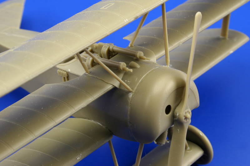
Page 7. The photoetch machine gun ( PE 8 X 2, 10 X 2, 15 X 2 ) provided in the kit are very suitable. The jackets (PE 8 X 2) are easily rolled into a cylinder shape on an appropriate sized piece of sprue or the forming tool from the DML kit item. For those of you with an all plastic kit the sets from Toms Modelworks or Part of Poland will do nicely for details. This allows the pieces to form precisely. I like to add the rear sights provided in smaller 1/72 scale kits at the are more in-scale for 1/48 than other aftermarket kits in 1/48. Note also that there is a metal plate with several pressed ridges under each guns blast suppressor attached to the cowling deck. If you can drill out the gun muzzles this is a nice touch. One technique to drill out gun muzzles is to take an .080 micro drill bit and push it through plastic sheet until you get a build up at the tip in a conical shape.
If your using monofilament as a rigging material then drill out the smaller cable holes. Also the larger cabane strut locator holes should be slightly deepened at this time. After adding the control horns ( PP C 35 X 3 ) I set the rudder (PP B 10) and elevators (PP B 3 & 8 ) to match the control attitudes that I had already chosen before starting to build. The Oberursel Ur. II motor ( PP C 24, 28 & PE 23 ) cylinders should be a darker color (gunmetal) than the boss plate (aluminum.) The air induction tubes (PP C 24) are noted as being a copper metal. Then give the whole assembly a coat of transparent /thinned earth-dirty tan.
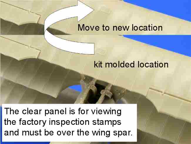
Page 8. Wait to add the cabane struts ( PP C 14 & 21). Check the wings for straight and level appearance. Some kit examples may need flexing in warm water. Again if your using monofilament it may be necessary to drill through the top wing ( PP A 10 ) for the dual aileron cables and the holes for the cabane struts. The clear inspection window in the top wing needs to be drastically relocated to a point where it would actually be represented as being over the wing spar. No raise edge either. How they got this wrong is still a mystery to most WWI aviation kit builders. So it should be sanded down and relocated in line with the main spar. The flare cartridge holder ( PP C 8 ) is an item that was added in the field and its location varied. When attaching the top wing (PP A 10) align it so that the pitch is similar to the others.
Page 9. Is the axle wing (PP A 6, 7, B 13 ) and wheel (PP B 9 X 2) assemblies. Sand off the details on the underside of the axle wing ( PP A 7 ). With the wing axle mid section (PP B 13) I routed out the plastic axle and replaced it with a brass rod of appropriate diameter. Next before adding the landing gear legs (PP C 15, 20 37 & 41 ) to the wing axle (PP A 6, 7, B 13 ) cut the legs down approx 1/16 of an inch on all four legs. There are 2 propellers types offered by the kit. Axial (PP C ) and Heine (PP C ) and note that Eduard has referenced the right application to the profile provide in the kit decals. It is the pitch and length of a propeller that determines the engine application. The paddle profile was the company hallmark. There are several ways of approaching the challenge of painting a laminated propeller. First give the item a coat of acrylic buff or linen. After thoroughly dry, give in a flat coat and let that dry. Paint the dark wood laminations in enamel on one blade. Then paint the other to match by using a simple paper template. Often I prefer to build my own laminated wood replacements. The Reich / government ownership plate ( PE 21 ) should be applied to the pilots right side of the cowling ( PP B 11.) It seems there should be a smaller plate over the larger one. Continue to rig the tail unit.
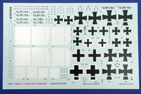
The Fokker decals
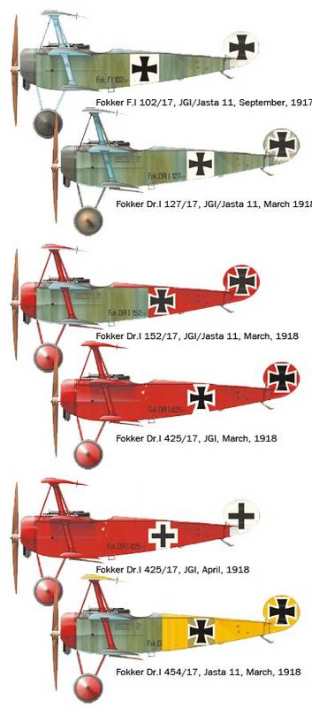
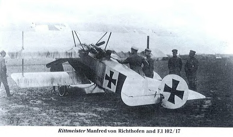
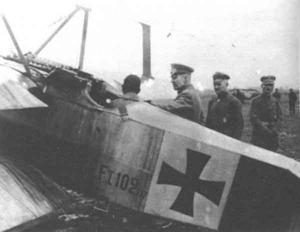
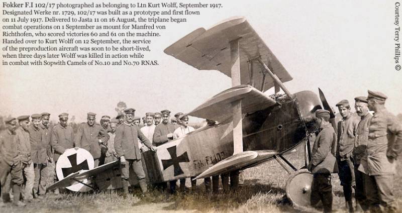
Page 10. Fokker F. I 102/17, 31 August - 15 September 1917. As flown by Ritt. Manfred von Richthofen
Page 11. Fokker Dr. I 127/17, March 1918. As flown by Ritt. Manfred von Richthofen
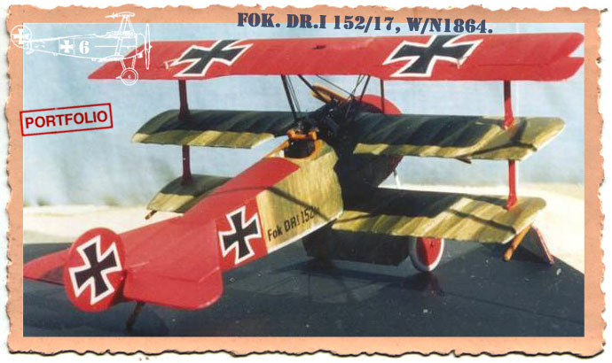
Page 12. Fokker Dr. I 152/17, March 1918. As flown by Ritt. Manfred von Richthofen
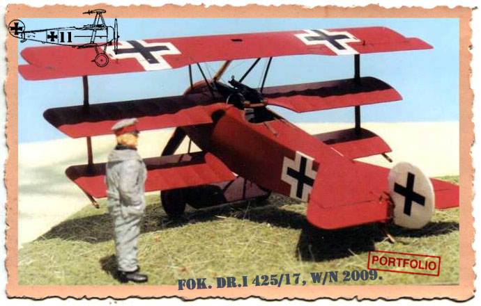
Page 13. Fokker Dr. I 425/17, March 1918. As flown by Ritt. Manfred von Richthofen
Page 14. Fokker Dr. I 425/17 , April 1918. As flown by Ritt. Manfred von Richthofen
Page 15. Fokker Dr. I 454/17, March 1918. As flown by Ltn. Lothar von Richthofen
Page 16. Wing Stencils and their locations for the F.I & the Dr.I.
Here are some furher notes on the decals from Srecko Bradic in Serbia.
"Decals are perfectly printed but have some minor errors. Type letter DR.I on the original plane is written in the style where the Roman numeral 'I' is a little bit smaller than the rest of the DR letters and on decals it is of the equal size. All you have to do is to trim this decal before place it on the kit. For the F.I model decals are perfect but not in the way suggested by Eduard. . ."
". . .Kit include decals for the preproduction F.I 102/17 and this plane for example did not use Axial logo stamp on the propeller. So you dont have to use it too. Also you dont need to use decals for the wheels and for the underside of wings as well there is no evidence for the same on the archive images. On the main wing strut you dont have to use decals with serials and letters but only decals with 1729. But most visible detail is the square background for the underwing cross on the lower wing. This area is presented as white and for this purpose is provided white decal. No need to use it at all as well this area is in the natural linen color. So paint this section in cream and the rest of the underside in the light blue color. Note that I have used for this area light cream color and I would like to note that one of the world top expert about this aircraft's markings, Terry Phillips, states that the same color of fabric is very pale (bleached linen). . ."
References,
Cross & Cockade Int. (GB) Vol. 3 #3, 1973
Cross & Cockade Int. (GB) Vol 6 #3 Fold out Cutaway diagram. 1975.
Cross & Cockade USA Vol 1 #1 p.36 1960
Cross & Cockade USA Vol 5 #1 Pp.1-29, 1964
Cross & Cockade USA Vol18 #2 Pp.164-176, 1977
Cross & Cockade USA. Vol21 #1 Pp. 81-90. Jasta 14, 1980.
Cross & Cockade USA Vol23 #4 Pp.318-334 Baumer & Dr.1 204/17, 1982.
Fighting Triplanes by E. Hadingham, Macmillian Pub. 1968.
Fokker Dr.I, by J.M.Bruce, Profile Pub. #55, 1965
Fokker Dr.I Aces of WW1, by Van Wyngarden/Franks, Osprey Pub. Aircraft of the Aces, series #40, 2001.
Fokker Dr.I ...A Reappraisal by A.Ferko & P.Grosz, Air Enthusiast Eight. Pp. 9-26,
Fokker Dr.I Datafile # 5 by R.Rimell, Albatros Pub. Ltd. 1987.
Fokker Dr.I Drawings by Dan San Abbott, WW1 Aero #122, 1988
Fokker Fighters by A. Imrie, Vintage Warbird Series #6, Arms & Armour Press.1989.
Fokker Dr.I, Flugzeuge die Geschichte Machten by J. Kranzhoff, Motorbuch Verlag, 1994.
Fokker Dr.I Jagdstaffeln by Greg VanWyngarden, Albatros pub. 2007.
Fokker Dr.I Special Datafile by R.Rimell, Albatros Pub. Ltd. 1991.
Fokker Triplane-ology by A. Imrie, C&C Int. Vol.23 #4, Pp.57-64, 1995.
Fokker Triplanes in Service by Dan San Abbott, Over The Front Vol 5.#4 Pp.326-339. 1990.
Fokker Triplane by A. Imrie. Arms & Armour Press. 1992.
German Fighter Units - June 1917-1918 by A. Imrie, Osprey Pub. 1978.
Pictorial History of the German Army Air Service by A. Imrie, Ian Allen Pub., 1971
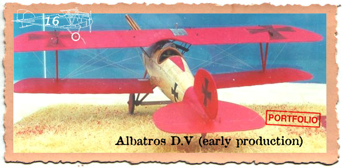
The Albatros D.V kit,
* 'Neu Breed of War Horse'
One of Eduard's best selling kits to date has been their 1/48 Albatros D.V/ Va kits. #8013, 8019 & 8030. Beginning with their premier Pfalz D.III (kit #8005) Eduard started a more sophisticated manufacturing practice that improved the overall detail, appearance and quality of their kits. This change moved Eduard away from limited-run slush mold manufacturing to computer aided/controlled high pressure injection molding. Their LTM process of molding kits brought them into the leading edge of model manufacturing.
At the beginning of 2002 we saw that Eduard released their * 'neu' mold of the Albatros D.V kits (Feb, #8109 and in March #8110 Profipack). The new process allows finer more exacting details be included in the overall plastic mold. It easily competes with any of the Tamigawa companies processes. Some people groused about the redo even if it were a new molding. Eduard explained that the attempt was to bring up the Alb. D.V kit to the same status as current production examples of other kits. This is a sound move. As the Albatros D. types were the backbone of the German Air Service (Luftstreitkrafte) there are literally hundreds of colour schemes that can be employed. Eduard has wisely assessed that this kit will have longevity.
Previously with every Eduard 1/48 Albatros D.V / Va kit I purchased, I had also purchase a etched metal set. Either the Toms Modelworks fret #210 or Eduard set #48218. It is the buildup for the Eduard #1136X version that we will discuss here. Also I will the include details from the other mentioned aftermarket etched metal frets.
Page 3. First, the cockpit structure assembly (PP B 6,12, 19,31 & 36) creates a manageable sub-assembly that is supposed to fit into the fuselage shells. The simulated support rods of the seat cradle dont seem to extend deeply enough in to the plastic rear cockpit wall (PP B 36) or the forward supports (PP B 12.) So I added the individual parts first not as a completed unit. Minor adjustments allowed everything to fit well. In the future I will modify the ammunition box (PP B 37) to fit higher than the recommended position on the forward cockpit wall (PP B 35.) If you dont the ammunition feed chutes dont seem to quite reach the Spandau inlet ports. This means grinding down the shoulders of the ammunition box by about 1/32 of an inch. The feed chutes on the ammunition box (PP B 37) needs a single line scribed across its face to denote an access cover. The pre-painted photoetch lap and shoulder harness straps (PE 1 & 2 X 2) should be shot with a wet clear dull coat before being bent or pressed in to the seat. Also the anchors (PE 16 & 17 ) need to be attached to the straps before they are secured to the rear bulkhead (PP B 36).
The fuel /air control panel (PE 6 & 7 ) is mounted to the fuselage right side (PP A 2) per instructions. Attached to PE 6 & 7 is the fuel quantity gauge . In the Profipack issue of the kit the panel has the switches (PE 15 x 4) as separate items. Some of the other improvements in this new mold are; Eduard provided the air pressure gauge to be located at the apex of fuel & air panel (PE 6 & 7 ) . The tube for the fuel tank pressure-hand pump (PP B 16) has the handle molded on as well. The same goes for the water pump greaser- tube (PP B 15) and its handle.
Page 4. On the rear machine gun brace (PP B 20) I add a slice of sprue to the rear of the tachometer to represent a backing cup. Then when dry paint and add the instrument face. Note, the tachometer was laid on its side for ease of reading in-flight and was a normal practice of its time. Cables and a lock can be added to the control column (PP B 18.) I like to replace the kit control yoke (PP B 22) for the column head from Toms Modelworks. The Toms item has the small throttle lever. For the D.V variant a circular pivot pulley (PP B 28) is impaled centrally on the forward leg of the control column (PP B 18) at its mid point. This was the pivot point for the aileron actuation and the cables extend upward into the top wing. When all cockpit items are in place I carefully add fine wire for the rudder and elevator control cables
With the attachment of the spark control box (PE 20 or PP B 23) one may want to erase the detail on the plastic part and use it or a plain scrap to add a depth th the photo etch and the left fuselage half (PP A 1.) PE 6 contains the magneto switch (circular instrument) and the spark control handle that the instructions tell you to fold upwards. Add a short section of wire to the bottom of the spark control handle leading forward under the starting magneto assembly (PP B 24, PE 10 &16) and disappearing into the forward cockpit bulkhead assembly. To be absolutely correct Eduard added a circular area in relief and there is representation of a key that was attached to the fuselage by a small chain but would reach to the circular instrument. (Much like a key to the ignition of a modern car.) The Bosch starting magneto (PP B 24) is a little thick if your using the bracket (PE 16)cut away 1/3 of its back side its thickness. There should be a bundle of ignition wires with a faded red insulation cover leading from the lower area of the spark control box (PE 6 or PP B 23) along the fuselage interior behind the starting magneto assembly (PP B 24, PE 10 & 16) to the forward cockpit bulkhead.
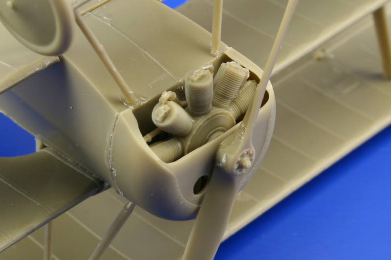
Now comes the build up of the generic Mercedes six cylinder inline engine (PP A 10 & 11, B 9, 30 & 32.) Erasing the center line seam and opening up the gaps between the cylinders is needed. Depending on your adherence to the exact placement of the engine bearer shelf (PP B 4) in relation to the forward cockpit bulkhead (PP B 35) you can adjust the sit of your motor by removing the 2 front lugs under the motor mount flanges on the sides. This lowers the front of the motor about 1/8 of an inch. Next, add R&R model detail nuts from Grandt Line to represent the motor mount nuts & bolts that would be apparent on the top face of the flanges. The upper portions of the cylinders are covered by water jackets and are the color of blued gun metal.
The early D.V types saw the installation of the Mercedes D.IIIa 170hp. It has a small air pump in front of the #1 cylinder. The rocker assembly ( PP B 32) is representative of the 170hp. The immediate visual difference in the early Mercedes 160 hp D.III / 170 hp D.IIIa and its progeny the 180hp D.IIIaü is the rocker springs exposed above the cylinder jacket heads. On the early D.III and D.IIIa motors the rocker springs are centered on the sides of the rocker box covers. On the D.IIIaü motor the springs are located on the forward leading edge of the same covers. The rest is below the cowling and not readily visible. Several good manufacturers ( specifically Roden) note the difference and have two distinct castings. The Mercedes 160hp was outclassed by 1917. The Mercedes D.IIIaü 180hp was the standard engine in both of the Albatros D.V & Va starting in late 1917 through 1918. Many, many D. III and IIIa type motors were rebuilt to the D.IIIaü specs at the airparks as the war progressed. That is why some captured examples had motors with the i.d. designation of 160hp D.III cast into their crankcases. This has caused the misconception that the standard 160hp and 170 hp were used in 1918 at a time when they had become obsolete.
Add fine wire painted black or white to make spark plug wires. Next I scratch build a reserve /main fuel tank assembly from a sandwich of 2 X .060 thou sheet plastic. These will rest behind the engine cylinders against forward cockpit bulkhead(PP B 35) & engine bearer shelf (PP B 4.). This tank should have two filler spouts and a fuel pump housing directly on top of the tank.
Concerning the twin Spandau Maxim machine guns, you may want to alter the cocking handle assembly (PE 23 X2) by modifying a simple lever with a rounded knob protruding at a 90 degree angle to the right. The Albatros fighters used T shaped cocking handles in the cockpit leading from the cocking levers on the right side of the gun breeches and worked via a linkage system. By the way Eduard provided a couple of T shaped handles to represent the seat adjustment clamps (PE 34 X2.) Since these are not readily seen, they could be reassigned to machine gun duties. Add small sections of sprue to represent flash suppressors at the ends of the gun barrel tubes that protrude from gun jacket ends(PE 29 X 2). If you can get a set of 1/72 scale rear gun sights the are perfect for the 1/48 scale guns. Add a set of ^^ brackets to the forward facing edge of the forward cockpit bulkhead (PP B 35) to simulate forward gun supports. I also added the empty belt chutes with bent solder/flux . If you use the left chute cover (PP B 7) you'll only need one chute for the right side gun.
Page 5. Pre-drill all strut and rigging locator holes. Join the fuselage halves (PP A 1 &2.) The only problem with that this new Eduard molding is the pilot's step located on PP A 1 is to far forward. It needs to be erased and then the replacement (PE 27 ) added one bay further back. Discard PE 26. Careful sanding helps the horizontal tail unit (PP A 14) fit properly. I used gap filling super glue (semi gelatin) to fill joint seams between all plastic parts joined to the fuselage. In the past I would usually add the Toms Modelworks or Eduard fittings to the fuselage at this point. It should be noted that on right fuselage half (PP A 2) the rear-most circular (right side) engine access panel needs to be erased in all cases of the D.V profile. This panel is evident only in the last production series of the D.Va types. When adding the tail skid (PP B 8 ) try to replicate the sit of this piece under stress by adding a .020 shim behind the bungee chords touching the skid housings (PP A 5) and painting the shim and the chord area the same color.
Page 6. Check all the pre-drilled strut and rigging locator holes. Add the radiator shutter assembly (PE 13 & 14) after you have painted or applied lozenge decal to the under surface of the top wing. I generally paint the undersurface of the top wing and the upper surface of the lower wing at this point before assembly and rigging. The radiator faces are molded on the top wing (PP A 3.) Realistically though, with minor scraping & sanding one can use any of the alternates available in the Toms Modelworks or Eduard frets. It depends on which one is applicable to the machine you are building. Note also, the etched metal covers (PE 31 & 32 ) are for the Albatros D.Va variant not the D.V . These were the upper surface access covers for the aileron pulleys.
Page 7. The seam on the exhaust horn (PP A 12) can be erased and the open end drilled out partially to simulate the original. Also I replace the cabane struts (PP B 21 X 2) with cut and shape brass rod of an appropriate diameter. Otherwise all other kit parts I add as per instructions. Next we see a prime example of a company listening to its customers. The one gripe that I have always heard from other modelers is that the original / early issue Eduard Albatros D.V /Va kits did NOT include the water pipes for the radiator intake and out flow. They are represented in the new mold as PP B 14 & 26.
The weakest part of a Veestrut landing gear assembly in plastic is the side to side twist. This causes the gear legs to break. I replace the landing gear legs (PP B 5 & 34) and the axle spreader bar (PP A 6) ends with the appropriate diameter brass rod. Check references for correct height of your scratchbuilt landing gear legs. I use upholstery thread to wrap around the lower legs of the landing gear with the axle in place to simulate the bungee shock chords. This looks like the original and actually secures the axle in place. Also a drop of Cynoacrylate here on the thread adds a great amount of strength. The kit rigging control horns (PE 28 X 4) can be used or replaced with the Toms Modelworks versions
Eduard pulled another minor faux paux by molding the retainer stud for the propeller (PP A 9 & 15) on the wrong face of the prop boss. I personally like scratchbuilding my kit propellers from light and dark woods. I have also learned to paint the laminations with convincing effect. Most Albatros fighters were equipped with the light and dark laminated propellers. Carefully check the aircraft profile your modeling to choose the right propeller. Don't limit your choices to the Eduard instructions. The D.V used both types of propellers that have been offered with in the kit. The propeller parent company determined the paddle profile of the propeller (it was their trademark) while the engine application determined its pitch and length. So profiles could be seen on either the D.V . Note the Alb. D.V had the cables rising from between the Spandau guns in to the underside of the top wing and traveling inside the wing to the bell cranks in the ailerons with only the shrouded control arms (PE 29 X 2 & 36 X 2 ) seen.
After final clear coating of your model attach your windscreen.
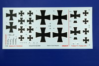
Albatros decals
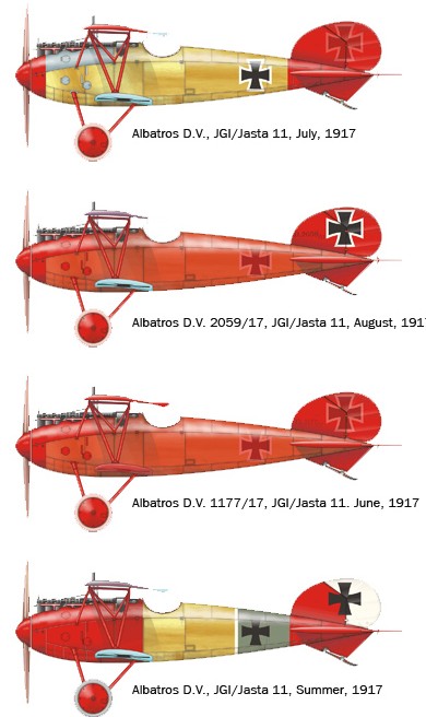
Albatros D.V serial unknown, 6 July 1917 as flown by Ritt. Manfred von Richthofen.
Albatros D.V 2059/17, 20 August 1917 as flown by Ritt. Manfred von Richthofen
Albatros D.V 1177/17 in June 1917 as flown by Ritt. Manfred von Richthofen
Albatros D.V Summer - Fall 1917 as flown by Oblt. Franz Muller.
Listed references
Albatros D.V/Va, War Horse of the Luftstreitkrafte by S.T. Lawson, SAM Pub. Model Aircraft Monthly, Vol 1 #2 , Pp.54-59.2002
Albatros D.V/Va, Part II, The Spoils of War by S.T. Lawson.
Albatros Aces by Franks 2000, Osprey pub.#33.
Albatros Scouts Described by Chas Schaedel, 1971 Kookaburra Tech. Pub.
Albatros Fighters Datafile Special by Ray Rimell, 1991 Albatros Pub. Ltd.
Albatros D.V by Peter Gray, 1965 Profile Pub.#9.
Albatros D.V & D.Va Described and Drawn by Ian Stair,1972 Scale Models.
Albatros D.Va German Fighter of WWI by Robert Mikesh, Smithsonian Inst. Press.
Lafayette Foundation Archive. Denver CO. USA.
Scratchbuilding Techniques by Alan Clark, 1990 Scale Models Int. Pp174-5.
Scratchbuilt Albatros D.Va by Alan Clark,1990 Scale Models Int. Pp.491-495.
Spandau Machine Gun by David Watts,1998 WWI Aero.
'The Last Albatros' by Colin Owers 1988 Aviation News Pp.216-221.
Please remember, when contacting retailers or manufacturers, to mention that you saw their products highlighted here - on AEROSCALE.
Highs: With the Fokker Dr.I you are purchasing a high quality kit that is the equal of the old DML / Dragon kit. The Albatros D.V is the re-release of the molding that was done only a couple years ago. Still some minor glitches there but easily a good kit. Lows: The lack of a second set of PE for the second Fokker Dr.I kit is particularly annoying. Especially when the kit costs as much as it does. They added fluff with the pin and resin figure of the dog. Verdict: While the Dr.I kit is very nice the marketing ploy that Eduard has used, has them second guessing the modeler. I know not course that others may take. But as for me, give me the choice or I spend my money elsewhere.
About Stephen T. Lawson (JackFlash) FROM: COLORADO, UNITED STATES
I was building Off topic jet age kits at the age of 7. I remember building my first WWI kit way back in 1964-5 at the age of 8-9. Hundreds of 1/72 scale Revell and Airfix kits later my eyes started to change and I wanted to do more detail. With the advent of DML / Dragon and Eduard I sold off my ...
Hi all
Eduard's original package never arrived, but I'm delighted (and relieved!) to say that the replacement landed safe and sound at Castle Aeroscale today! So, true to my word, I'll start a build thread on the Dr.1 as soon as I get a chance (trying to balance it with other Review commitments). I'll work basically OOB to give Stephen maximum scope to add the details.
All the best
Rowan
Greetings all;
I had a request to know more about MvR's Fokker Dr.I 425/17. Since Roxter will be building the Eduard kit I decided to address it here.
This thread is not really about Dr.I 425/17 but here is an older build of mine. Most research fiends and historians know that Dr.I 425/17 was custom painted for MvR at the Schwerin factory. Though there was no olive green streaked camouflage on the upper surfaces. Some authentic samples we have show light blue paint under the red paint. But chipped paint from the upper surface only shows the clear doped fabric under the red.
The stencils were reproduced but evidently in the field were overpainted when the crosses were changed. This is still a point of contention to many. I use Testors Insignia Red ( 8 parts) with Testors Brown #1166 ( 3 parts.) The Testors Brown is a light color with yellow/orange terra cotta color. More a medium brown. This creates a very flat 'Indian Lake Red' that R. Rimell avowed in his Windsock special 1988. Thoroughly mixed its great. I keep a bottle of this mixture around and use it mixed with other colours to lighten or darken as needed. When you do it its the unmistakable blood red. Also A. Toelle has seen good samples of MvR fabric (German 50 count calendared fabric) he seems to agree. The information we have on 425/17 can be verified in 'Richthofen' by the late A.E.Ferko Albatros Pub. Ltd.
Can I just say...
I saw this in the box last week at IPMS (Vic Hobby Center in Melbourne always bring along a big box of new releases for us to drool over... and purchase if we wish (I came home with the Trumpeter 1/72 Vickers Wellington Mk IIIc (Don't tell my wife!) Will that qualify as Early Aviation?)). The Dr.I is a lot more subtle in real life than photos indicate.
I was actually considering handing over some readies when I saw the $130 (Australian) Price tag. I could get a Montex 1/32 Fury for that!
Cheers,
Hugh
I've found Eduard's manual for their Der Roten Flieger kit - as I want to build Manfred's Dr.I. Here's the download link link.
What I don't understand is that how the cockpit walls should be painted olive drab while the whole fuselage was painted red? I thought the red colour would be seen also on the inner walls of the cockpit.
From the rules of modeling.
". . .#16.) The kit instructions may be very interesting, (especially concerning colour notations) but are 95 % of the time irrelevant. . ."
I quote that one a lot. The interior should be CDL - clear doped linen.
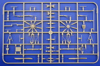
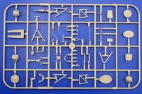
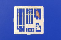
The Fokker F.I and Dr.I PE is on one fret. But only accomidates eith one build or the other.
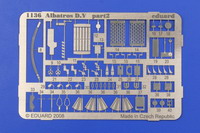
Albatros basic PE
Eduard provides a pre-painted set of PE for the Alb. D.V kit as well.
While generally good in proportion. The resemblance to the brothers von Richthofen is only a slight one.
Back in WWI small pins or smaller versions of a man's award was worn by his true love back at home. Eduard provides a one-sided faux Blue Max in miniature in both the 1136 & 1136X kits.
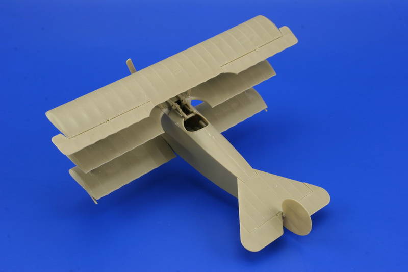
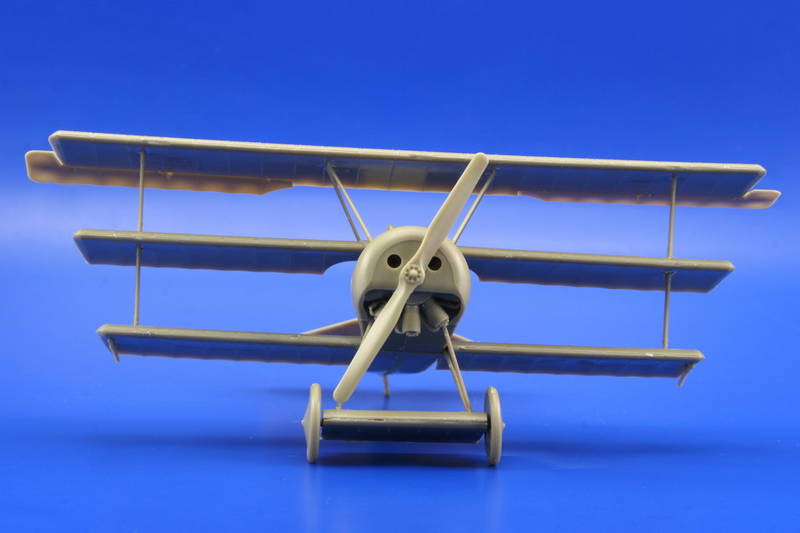
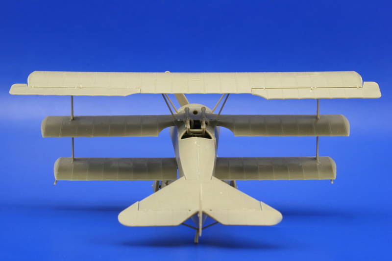
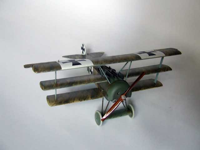
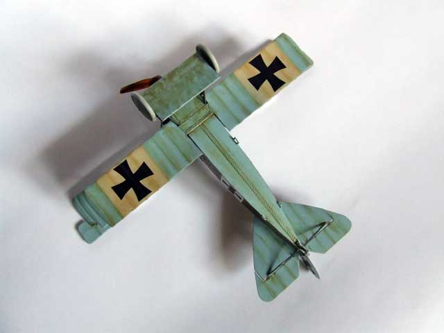
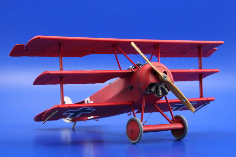
Even as badly as the knock up's landing gear was fouled up the wings were mounted plumb and square with each other.
The obverse side of the Blue Max pin from Eduard.
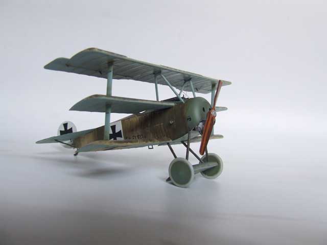
The builder did not get the landing gear legs set in the locator holes at the right depth. Easy enough to fix. Why didn't they?
I used the kit mold to show the relocation. In truth there should not be a raised edge. It is clear covered in a Cellon. Simply erase the edge and relocate hole. Then fill with a clear section of sprue.
This kit that was knocked together for the Eduard website was poorly done. The Spandau guns should be the all plastic versions with the vented / fluted barrel covers. The middle wing cowling has a poor edging to it. Glue joints are somewhat cobbled.
This basic kit was knocked together for Eduard's website in a poor fashion. The only real different in this kit and the DML is the underwing representation and the current price.
Three Alb. D.V types flown by MvR and one flown by a member of Jasta 11.
The F.I and some of the Dr.I airfcraft the were flown by MvR at various times.
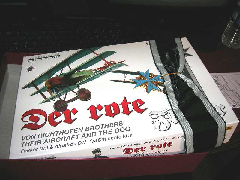
Just after I open the red box here is what I see.
This one sided Blue Max is at least a better attempt than their previous issue in the Royal build. I have seen thse types used in uniform displays by collectors.
Join me as I crack open this kit
A. Fokker in cockpit, General, MvR and Adam
Eduard model built bt Srecko Bradic of Serbia.
Eduard model built bt Srecko Bradic of Serbia.
Eduard model built bt Srecko Bradic of Serbia.
Eduard model built bt Srecko Bradic of Serbia.
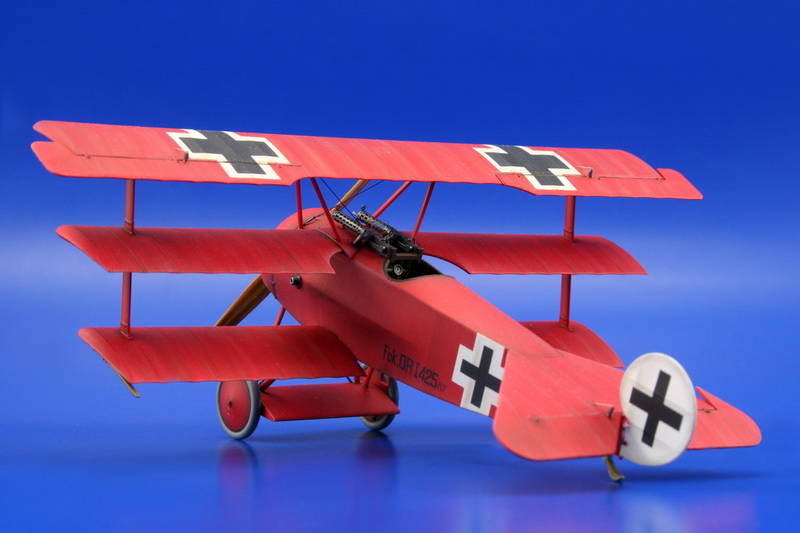
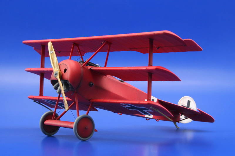
Eduard has now put a build up of the kit that seems to be plumb and square 6/28/08. Though the red is questionable from what we have of actual samples. And the serials on the real airframe were overpainted. These should be barely visible.
The serials on the real airframe were over - painted. These should be barely visible. Also the Axial propeller logos were put on upside down.
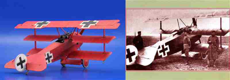
Here is a comparison of the Eduard kit to the original Fok. Dr.I 425/17
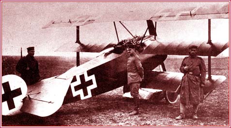
Here the original Fokker Dr.I 425/17 is under local guard while MvR stops off for a visit to a nearby 2 seater unit. Probably taken a day or two before April 20,1918. He was later KIA in this machine on April 21, 1918.
One more issue is that the Axial propeller logo is upside down in its placement.
Eduard has now put a build up of the kit that seems to be plumb and square 6/28/08. Though the red is questionable from what we have of actual samples. And the serials on the real airframe were overpainted. These should be barely visible.


Comments