The prototype was completed in 9 February 1916 and sent to RAF Upavon for testing in late March. The Royal Naval Air Service (RNAS) quickly ordered two more prototypes, then placed a production order. Sopwith was heavily engaged in production of the Sopwith 1½ Strutter, and produced only a small number of Pups for the RNAS. Deliveries commenced in August 1916. In May 1916, the RNAS received its first Pups for operational trials with "A" Naval Squadron. The LeRhône engined Pup quickly proved its superiority over the early Fokker, Halberstadt and biplanes. After encountering the Pup in combat, Manfred von Richthofen said, "We saw at once that the enemy aeroplane was superior to ours." It was to prove itself as the first shipboard fighter and in the vanguard of the BEF over the Western front during 1916.
Kit History:
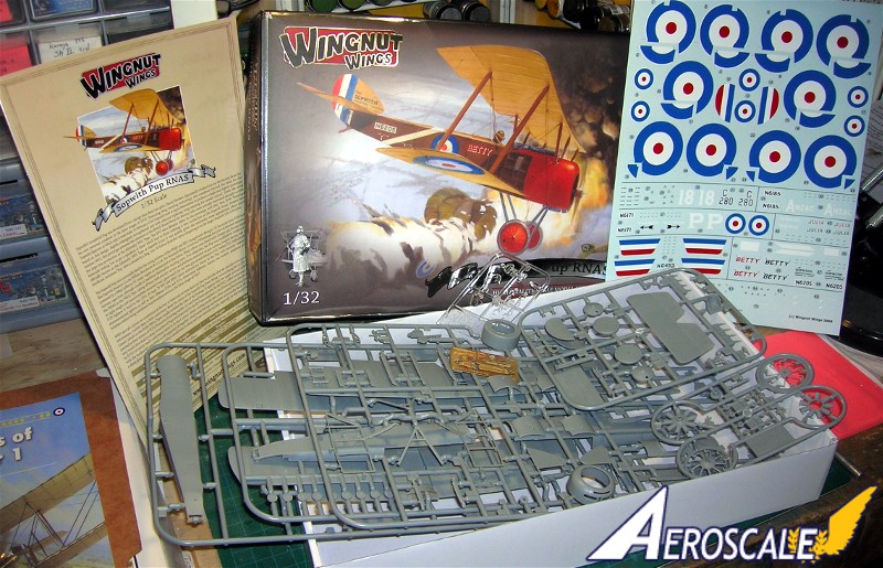
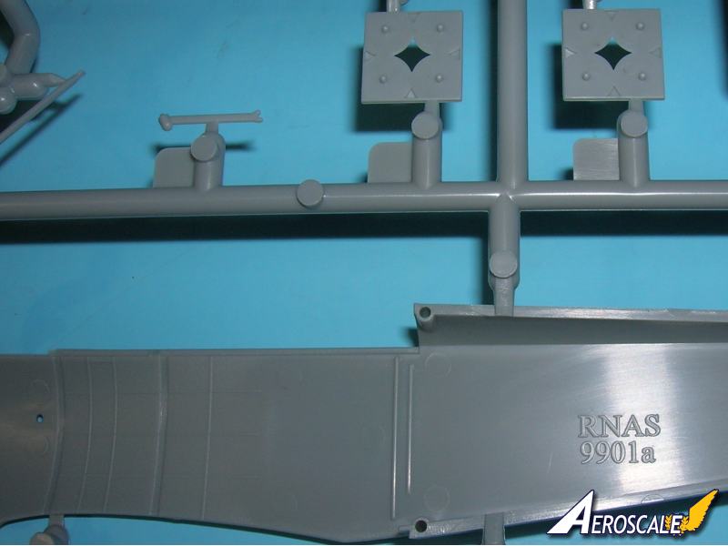
It was in April 2009 that the Wingnut Wings website announced their 1:32 kit and listed as coming soon. Then on 5 September 2009 that this kit was previewed at the Wellington Model Expo. It was noted that there would be 2 different versions. One for the #32013 RFC (9901) type and the other was based on the #32016 RNAS (9901 & 9901a) type. Mine arrived at the end of January 2010. I remember the first kit review I published back in 1998 concerned a 1:48 model kit of the Sopwith Pup. Now to begin.
The cover page to the 24 page instruction monograph contains the background, data and history of the original aircraft.
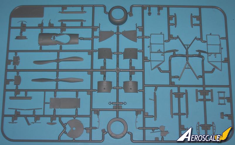
Page 1 has the legend symbolic keys for actions to employ or not to use, paint recommendations and page 2 has the kit parts map. Some areas are shaded to not parts not meant for use with this build.
The build:
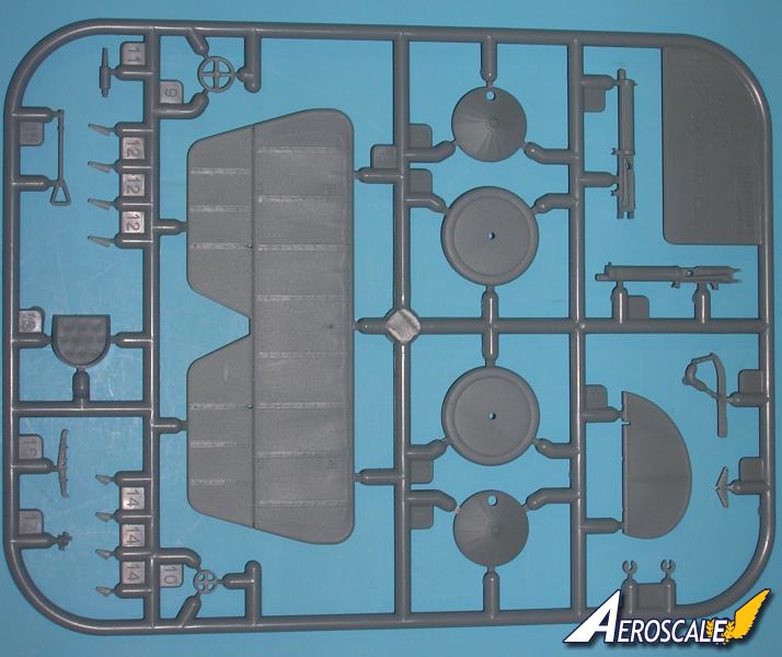
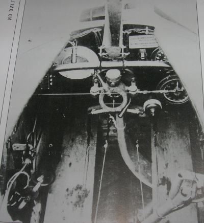
The best place to start with is the clean up of parts, erasing all molds seams. Pay close attention to the seams on the edges of the fuselage, wings, horizontal and vertical tail unit. The parts map on the second page of the instructions will guide you to your plastic pieces Pre-drill all rigging holes at this time. Assemble the cockpit parts in the Wingnut Wings (WNW) recommended sequence. Note to their credit WNW has corrected an age old faux paux on page 5 of the instructions. In several previous references the images of the Pup cockpit has been reversed.
Step 1. Being that varnished wood is prevalent in most WWI aviation subjects, consider that Sopwith products are high on that list. Simulating wood veneer is pretty easy. Each component of the cockpit assembly (PP A 17, 19, 26, 29 - 31, 33, 34, 37, 39 ) and (PP B 15 & 16 ) needs individual attention as to its construction media. Metal, wood and fabric all play a role here. If your going to model the Pup with control surfaces in an actuated positions here is the time to set the control column & rudder bar in complimentary positions.
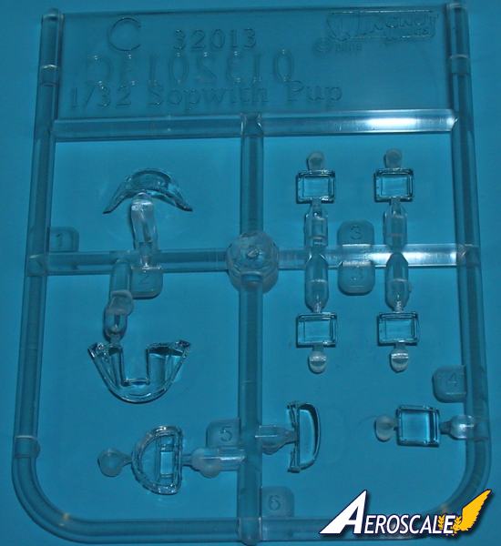
To simulate wood I will paint a base coat of acrylic buff or linen colour. When thoroughly dry I will apply a clear flat coat. When that is dry, I will begin streaking a brown enamel wash over the area with an older brush. Several coats may be needed. In the next sub assemblies all hardware items of metal can be painted aluminum with black knobs and handles or medium grey entirely. Page 4 shows clear routes of the rigging (blue) and control cables (green). For the instrument panel (PP A 13 ) I will drill out the center plastic of the gauges and add a clear backing with the decal for the gauges placed over the clear areas and then paint the backs of the dried decals and the clear panel to seal the deal. For the RNAS 9901a version WNW suggests you add the Lewis gun ammunition drum storage assembly (F 1 X 2 & 6 X 8 ). In doing this they recommend you detach the oil pulsometer from the right side internal structure ( PP A 17 ) Dont throw it away. Add the detached part to the lower left of the instrument panel ( PP A 13 ).
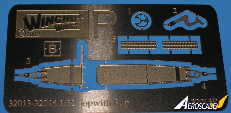
Step 2. The brass etched pieces are readily marked on the fret itself. Anneal the seat belt straps (PE 3 & 4 ) by passing them over a heat source. Dont plunge the part into an open flame. You want to soften the part, not cook it to the point that it is brittle. Paint the part with a flat colour then when it is dry use flex film on its raised sections. This will reveal the brass buckles and eyelets in relief. Carefully form the part, attach it and touch up any scuffed or exposed areas. Add these PE items to the seat (PP B 13 & A 43 ) assembly as shown. The next cockpit additions include the fuel /oil tank (PP A 7 ) The original had an inner partition to accommodate both substances in one container. Then the instrument panel assembly (A 13 & B 17 ) and the arched rear Vickers machine gun support (PP A 7 ).
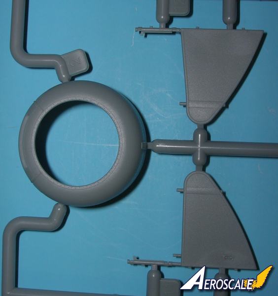
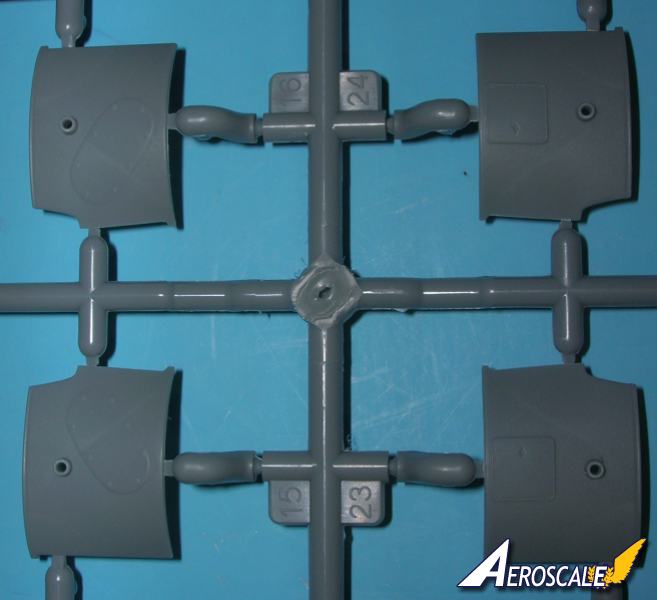
Step 3. The tail skid and fuselage facade details section notes the difference in the adjustable (PP D.1 , B 2 & 11 ) and fixed (PP D 1 & B 2 ) type of horizontal tailplane details. There is also cowling variations (PP A 15 & 16 or 23 & 24 )in the types of access panels to the rear of both the firewall and the rotary engine. Check your profiles.
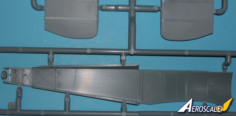
The cabane struts are one of the best features structurally speaking. The rear cabane struts are moulded to the internal fuselage sides (PP A 17 & 19 ). I just wish other manufacturers would follow suit. The moulded cabane struts integral with the fuselage halves can make short work of wing alignments.
Step 4. Details the horizontal tail surfaces and control horns (PP B 8 & 12 X 2), cockpit decking (PP A 10) and the variation for the unarmed profile with (PP A 44) added. Next the rudders vertical stabilizer variations for the adjustable (PP A 11) or the fixed (PP A 12 ). The rudder (PP B 3 & 5 ) assembly is straight forward with the admonishment to add the decals before adding the control horns (PP B 3 ). WNW gives you two fuselage set ups. For the 9901a ( PP F 7 & 8 ). For the 9901 (PP D 1 & 4 ).
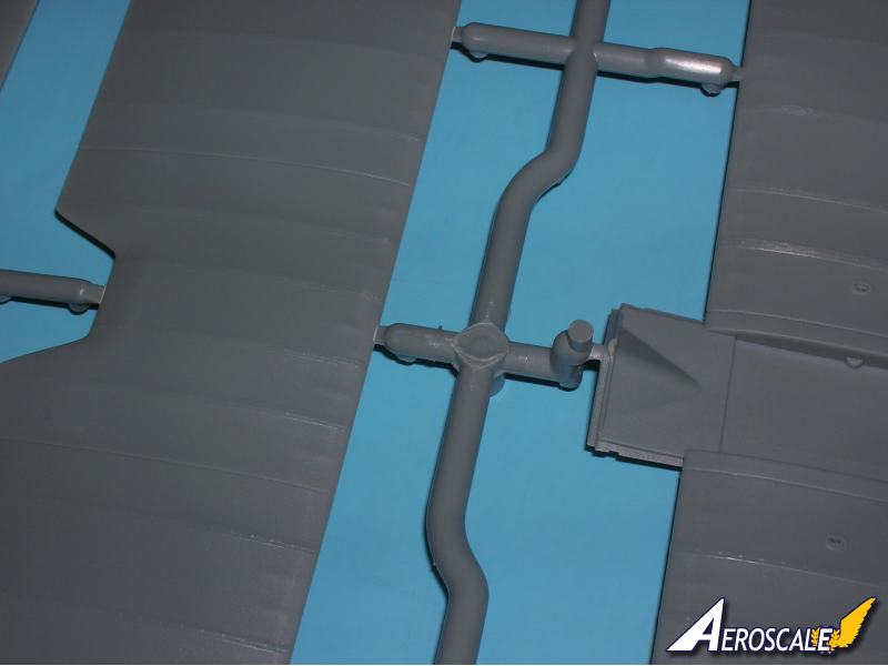
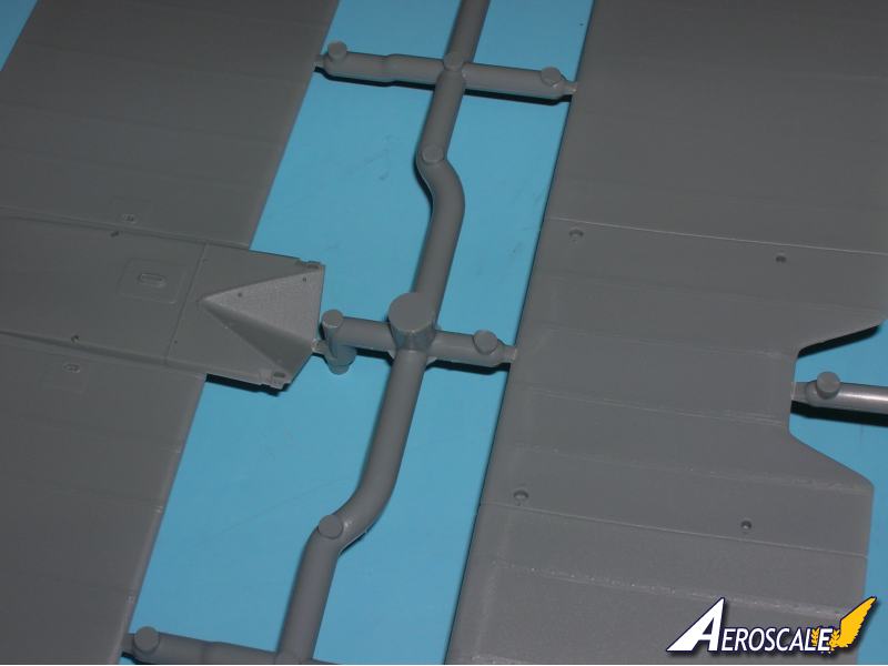
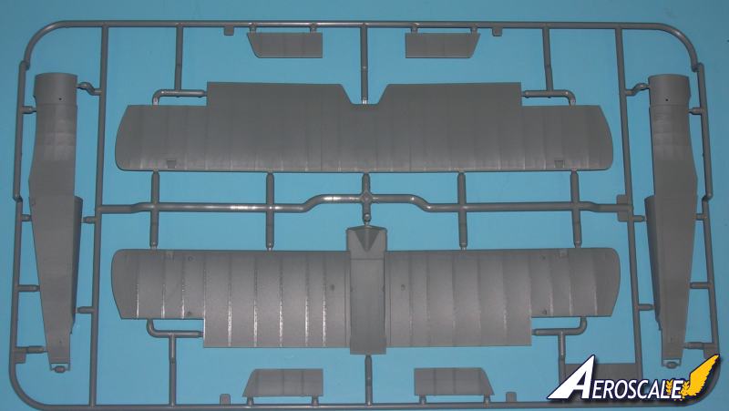
Step 5. I separated the both wings (PP D 5 & 6 ) into six sections. Note that on the real a/c the top wing is in three sections and the lower wing is in three parts as well. Checking the rigging and strut locator pips. These sections of the Pups wings were attached to threaded unions protruding from the fuselage and the center section producing a noticeable gap. Using brass rod here will help you adjust the dihedral as you go. I also put brass rod into the pre-drilled ends of the struts.
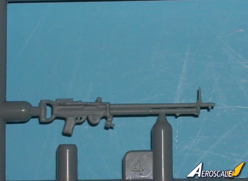
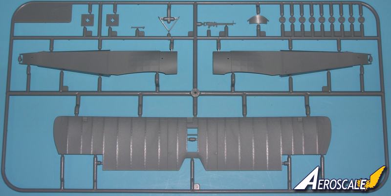
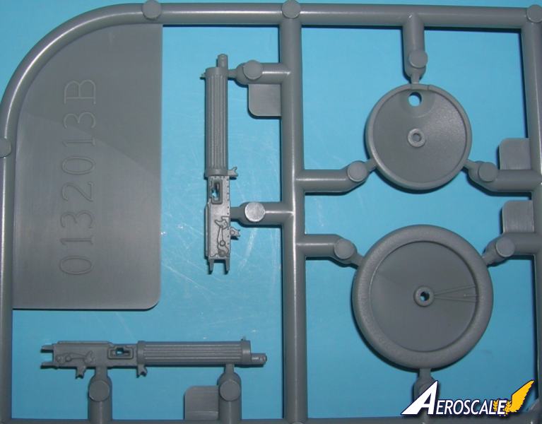
Step 6. The Vickers machine gun (PP B1 & C 5 or A 4 ) assembly is shown. I will save adding the clear windscreen (PP C 2 , 5 or 6) until a last step. Or you can go with the Admiraty prescribed Lewis machine gun mount ( PP F 2 & 3). But dry fitting it is a good idea.
Step 7. Rigging can now be applied. I used a Smoke gray invisible thread in short sections. I anchor one group of threads with Super- glue, then pass the other ends through their holes and clip spring action wooden clothes pins to their ends. Then secure those ends always using Gap Filling Super Glue, but sparingly. With the Pup youll find 2 pairs of rear inter-plane rigging wires pass from the fuselage underside through the lower wing to the area adjacent to the upper end of the inter-plane strut. Builder be warned. I then run the other ends of the strands through their holes and attach a clothes pin to draw the line-s taught (One clothes pin per line). Next a small drop of thin Superglue and wait for it to dry completely. Yes, I know that Im being redundant but believe me its important to a well built kit. Now add the Ailerons in concert with the control column position. These parts are stabilized with brass pins in pre drilled holes. If your going to model the Pup with control surfaces in an actuated positions here is the time to do so. If your really AMS afflicted you can soften the detail on the under surfaces of the wings with the application of sanding film.
Next is the RNAS Lewis machine gun ( PP F 4 & 6) installation when using the RNAS wing (PP F 9 ).
Step 8. If your going to model the Pup with control surfaces in an actuated positions here is the time to do so. Now add the Upper wing ( PP D 6 ) ailerons and control horns (PP D 7 & 8, B 14 X 2 ) in concert with the control column ( PP B 15) and rudder bar ( PP B 16 ) positions. These parts are stabilized with brass pins in pre drilled holes. If your really AMS afflicted you can soften the detail on the under surfaces of the wings with the application of sanding film.
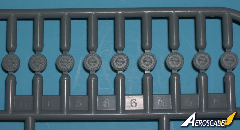
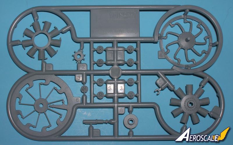
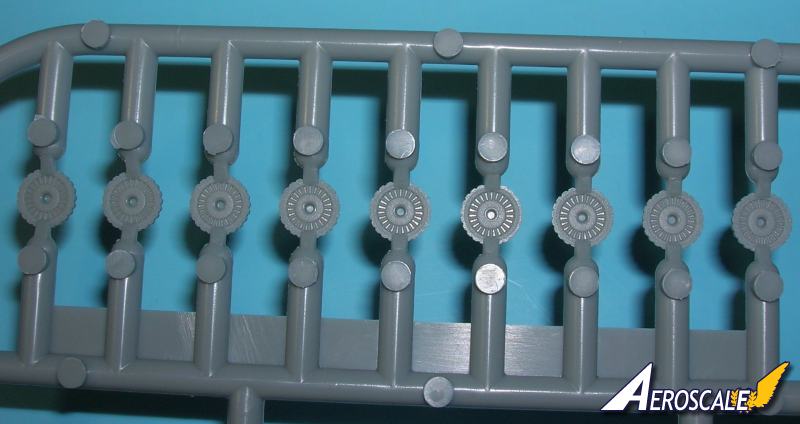
Step 9. The 80hp LeRhône rotary 9c engine ( PP E 1, 3 X 9, 4 - 9 ) consists of 17 pieces and as been notes elsewhere is crisply moulded. A wiring diagram is provided for the spark plug leads (which not included but would be easily made from wire or heat-stretched sprue). Now here is the rub. The air induction pipe unit (PP E 4) needs real adjustment by most accounts, to meet with the engine cylinder head assemblies. There will have to be some bending for all pipes to connect. But WNW has really done a superior job of providing the modeler with detailed images of the real engine on the same page.
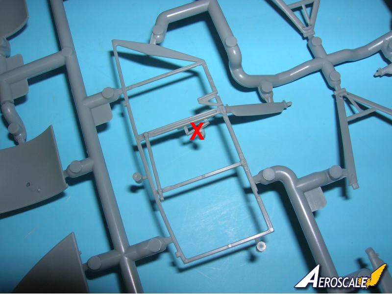
Step 10. Adds the lower wing ailerons and the ir control horns.(PP D 2 & 3 , A 8 X 2) Note the way they should attach. I also put brass pins in these ailerons and in the ends of the Landing Gear struts (PP A 18, 20 ). I will also replace the split axle (PP A 28) with a bent brass rod item for strength. The axle wing (PP A 25) and other under carriage items(PP A 27 X 2). The remaining items (PP B 4,6,7 X 2 ), fit on with the recommendation of not using any adhesive.
Step 11. Note the cowling (PP A 2 or 35 ) propeller (PP A 14 or 22 ) variations. Also the rear prop boss insert (PP A 3 ) is a very neat item I found handy when doing the WNW Junkers J.I. The insert not only allows them to avoid sink marks in production but provides a good deal of strength.
Step 12. Notes all the rigging paths..
Camouflage:
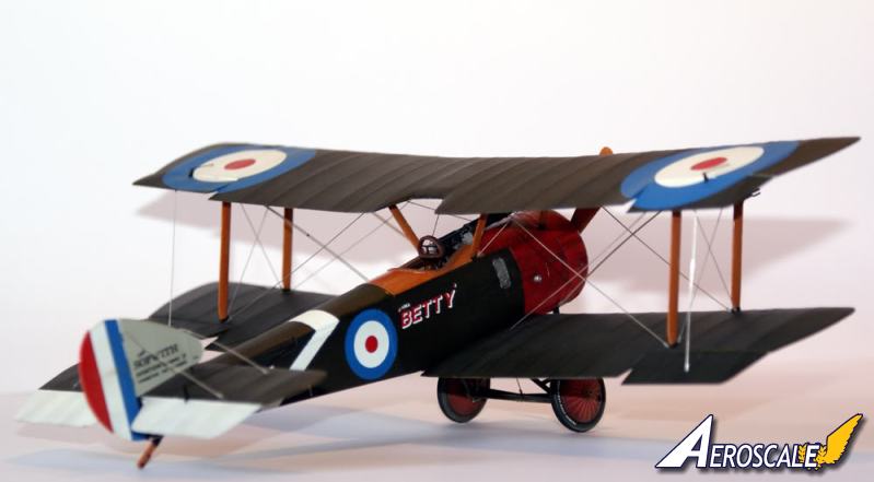
The Pup left its parent and various license contract manufacturers with a coat of PC 10 on all upper face fabric covered areas. The fuselage was even painted this on the under surface. The under surfaces of the wing panels and horizontal tail unit were clear doped. The metal cowlings were usually painted in a light to medium grey tone. Now on the Beardmore built Pups from series of 128 aircraft N6443 - 6459 had the clear doped linen included the fuselage sides and the undersurface.
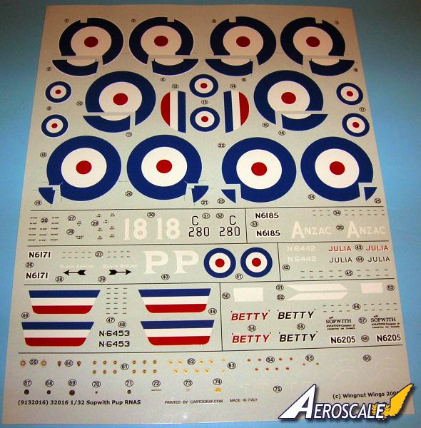
Profiles:
A. C280 18" was a Standard built machine assigned to the War School at Manston and flown by Lt. Goudy in June 1918.
B. N6171 Black Arrow was a Sopwith built machine assigned to 3(N) Sqn and flown by FSLt. Pierce in April & May 1917.
C. N6185 Anzac was a Sopwith built machine assigned to 4(N) Sqn and flown by FSLt. C. J. Moir during April - May 1917.
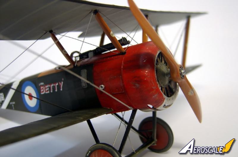
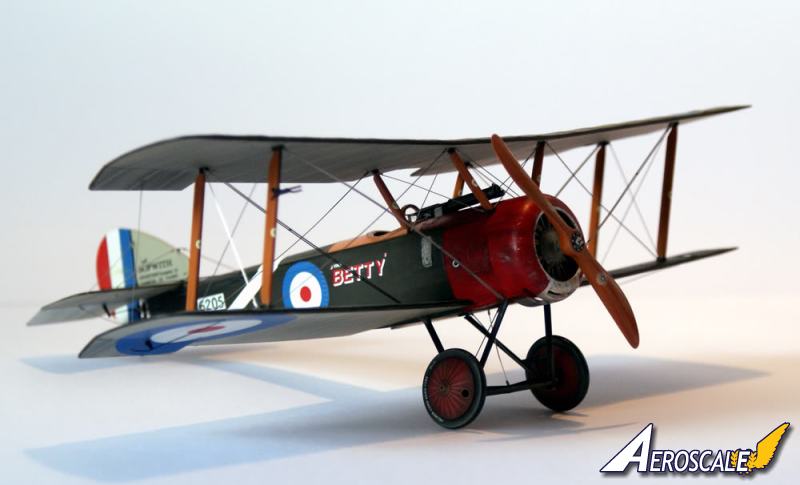
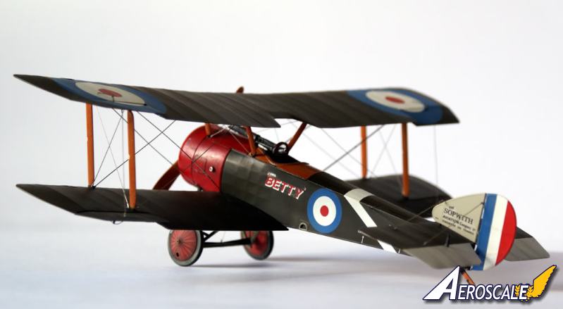
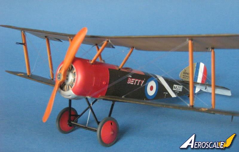
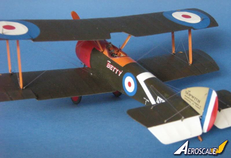
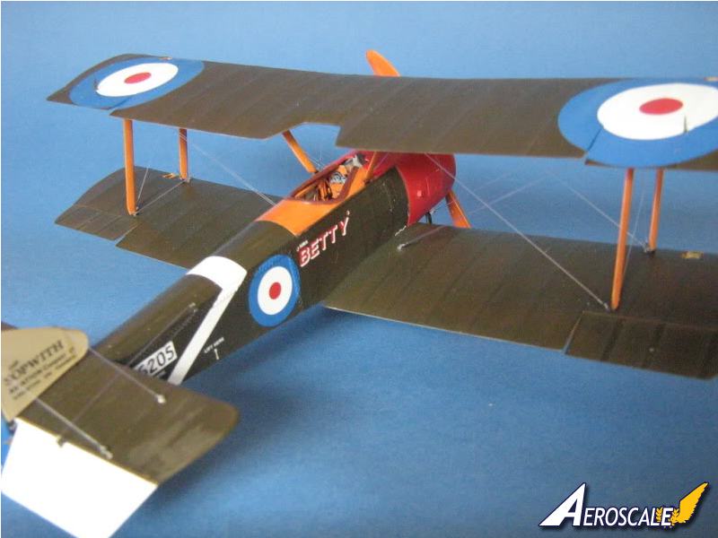
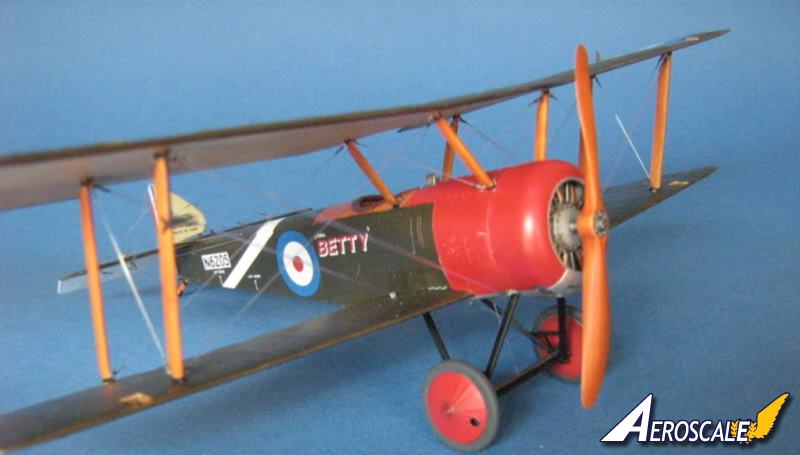
D. N6205 Betty was a Sopwith built machine assigned to 3(N) Sqn and flown by FSLt. J. S. T. Fall during April -May 1917.
E. N6442 Julia was a Beardmore built 9901a machine assigned to the Anti-Gotha Walmer Defense Flight and flown by FSLt. J. A. Shaw in June 1917.
F. N6453 was a Beardmore built 9901a machine assigned to the HMS Furious and flown bt S/Cdr E. H. Dunning in August 1917 and HMS Repulse S/Cdr F. J. Rutland in October 1917.
Extra detail decals include;
1. The cockades are cookie cutter types for applying to the ailerons. These are provided in two versions in the RNAS kit set for cockades that are in either inboard or outboard positions.
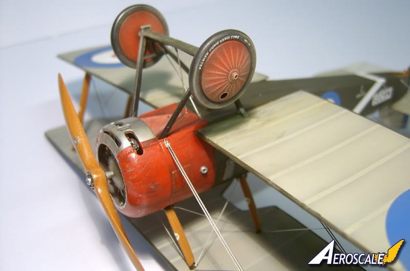
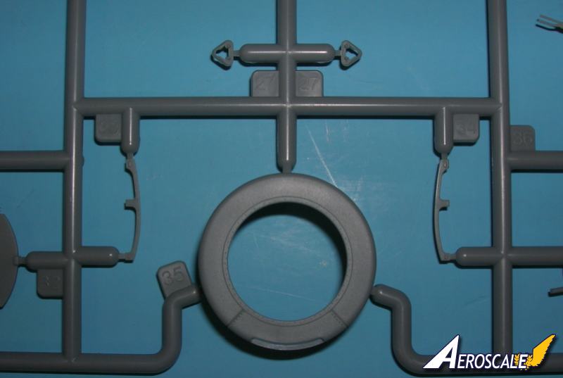
2. Palmer Cord Aero Tyre decals for the tyres 700 x 75.
3. Manufacturers decals for the propeller (RNAS:3 different types) interplane struts (RNAS: 3 different types).
4.faces for the instrument gauges, placards, Lift Here markings and numerous manufacturers stencils for applying to the wings, tailplane and fuselage are provided.
5. Options for Julia and Betty markings in red or black lettering.
References:
Air Enthusiast #4 Pp.187-207.
British Fighter Units Western Front 1917-18 by Alex Revell , Osprey Airwar #18, 1978.
Cross & Cockade Int. Vol. 19, #1, Pp. 1-25 Esp. Pp. 4 ,14, 16 &19. 1987
Cross & Cockade Int. Vol. 23, #1, Pp. 34-41. 1991
Cross & Cockade USA Vol. 23, #3, Pp.193-214. 1984.
Profile #13, The Sopwith Pup by J.M.Bruce. 1965
Quarterly Review Pp. 4-12 Sopwith Pup...First Carrier Fighter. by R. Hucker, date unknown.
Royal Flying Corp in WWI by R. Rimell, Osprey Vintage Warbirds series #1, 1985..
Sopwith Fighters in WWI by J.M.Bruce, Osprey Vintage Warbirds series. #3, 1986.
Sopwith Pup Aces of WWI by Norman Franks, Osprey a/c of the Aces, 2005.
The Sopwith Pup by J.M. Bruce, Gordon Page and Ray Sturtivant, published by Air Britain 2002.
Windsock Datafile #2 , Albatros Pub. Ltd.
When contacting manufacturers and publishers please mention you saw this review at AEROSCALE
Highs: This kit has a great amount of detail and forthought in its layout. Details are in scale and fit tolerances are good. Lots of unexpected details, guns, ammo drms and their mounts.Lows: The motor is split in halves front and back. The seam line will be tough to remove.Verdict: This is a great kit and with almost everything a modeler looks for in an enjoyable build.
Our Thanks to Wingnut Wings! This item was provided by them for the purpose of having it reviewed on this KitMaker Network site. If you would like your kit, book, or product reviewed, please contact us.
About Stephen T. Lawson (JackFlash) FROM: COLORADO, UNITED STATES
I was building Off topic jet age kits at the age of 7. I remember building my first WWI kit way back in 1964-5 at the age of 8-9. Hundreds of 1/72 scale Revell and Airfix kits later my eyes started to change and I wanted to do more detail. With the advent of DML / Dragon and Eduard I sold off my ...
This is what I see when I try to go to the review page:
"This review either does not exist or has not been published for public viewing. Please contact us if you think you believe this is in error."
Thats what I get when I take a nap in the middle of writing a review. Try it now. Thats right Terri (think I spelled your name with 1 "r" last night. . . The pusher book has been a favorite read for me. I have that DH 2 to finish. By the way here is a correction to this kit from the WNW website.
But come to think of it 40 winks wouldn't sound bad about now. Zzzzzzzzz. . .


Comments