The initial versions were introduced in 1914 at 120 - 160hp, but a series of changes improved this to 170hp in 1917, and 180 by mid-1918. These later models were used on almost all late-war German fighters, and its only real competition, the BMW III, was available only in very limited numbers. Compared to the Allied engines it faced, the D.III was generally outdated.
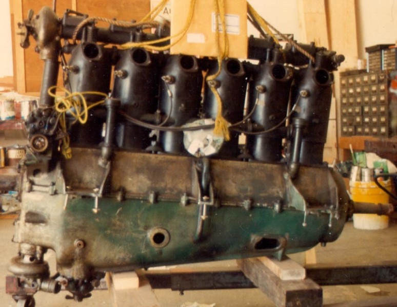
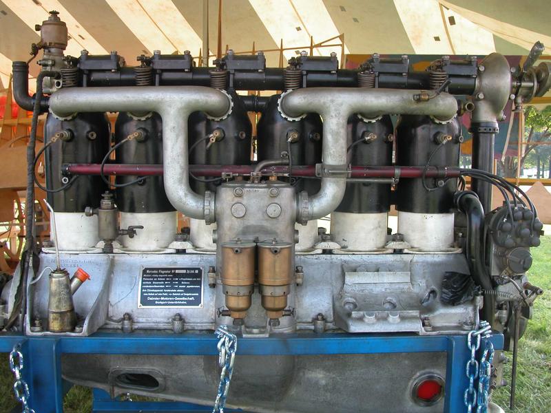
Like most inline engines of that era, it used a large aluminum crankcase as the main structural component, with separate cylinders made from steel bolted onto it. The technology for screwing a threaded cylinder of steel into an aluminum crankcase did not exist at that time. Jackets for cooling water covered the top 2/3 of the cylinder, feeding a radiator via connections at the back of the engine.
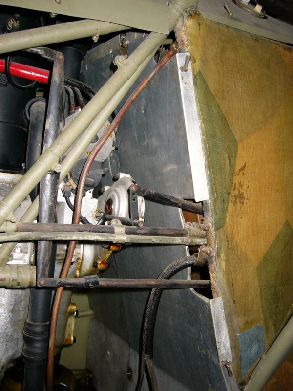
The D.III featured a rather prominent overhead cam operating the single intake and exhaust valves, powered by a shaft running up from the crankshaft at the rear of the engine. Ignition was provided by two sets of spark plugs, one located on either side of the cylinders, each powered by a separate magneto for redundancy. The ignition cables were protected in tubes running down either side of the cylinders. Fuel was fed into the cylinders via pipes on the left side of the engine as viewed from the rear, supplied from a twin-barrel carburetor located just above the crankcase. Both the fuel and oil reservoirs were pressurized by an air pump run off the crank, The only obvious design change from the earlier D.II was to use separate cooling jackets for each cylinder, whereas the D.II used one jacket for every two cylinders
The original D.III was introduced in 1914. It saw widespread use in 1915-1916 examples of the B & C-series of German, two-seat general-purpose biplanes. The D.III did not see use in fighters until 1916 when the fighters grew to need that level of power to reach altitude and combat two seat aircraft of the enemy. By 1917 the D.III was being widely used in fighters, most notably on the famous Albatros D.I & D.II types. Production of these 160hp motors were essentially wound down by May 1917, with only a handful of the 160hp motors continuing to be delivered until October 1917 for use in unarmed trainer aircraft.
D.IIIa
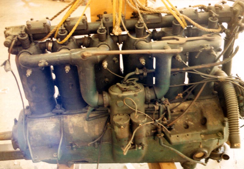
Continued development of the basic design led to the slightly modified 170hp D.IIIa, which took over on the production lines in June 1917. The main alteration was to change the piston profile to have a flat head instead of the former concave version, thereby slightly increasing maximum compression. Other changes were mainly in design details, notably a redesigned crankcase and new carburetor. Many of the accessories were also redesigned or moved around on the engine. One such visual change was to move the narrow upright air pump from the rear to the front of the motor. This model was produced and used from about summer to fall 1917. From early models through the late 170hp motors had rocker arms that operated the valves had square covers positioned directly over the cylinders with the rocker arms exiting through vertical slots cut into the sides of the boxes.
D.IIIaü
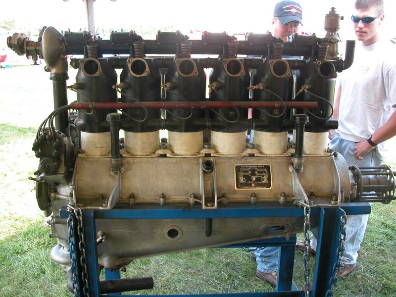
A more "radical" upgrade was the 180/200 hp D.IIIaü, introduced in late 1917, the D.IIIaü was a standardized refinement of the D.III and D.IIIa design and the ü designation was never official. This engine changed the pistons again, this time to a domed profile that further increased the maximum compression the ü was for "über", meaning "overcompressed". Additionally, a new altitude-compensating carburetor was added, which improved performance at higher altitudes. To support operations at these altitudes, water from the radiator was used to heat the air intake and prevent icing in the carburetor. The water pump was also moved from the rear upright tower to the underside of the crank case near the oil pump. The aü model, which included upgraded D.III and D.IIIa engine blocks, was the most prolific German fighter engine of 1918 and designed into most fighter designs from late 1917 on. This included most of the entries in the First Fighter Competition at Adlershof in January 1918, notably the famed Fokker D.VII.
In this version of the engine, the boxes covering the rocker arms that operated the valves were moved rearward and the cylindrical rocker arm shafts protruded forwards through the front surfaces of the boxes, operating the now fully exposed rocker arms with the exposed shaft ends. The newer arrangement were stated as being interchangeable as a set with the complete camshaft, rocker boxes, rocker arms and valve springs, with the D.III's earlier cam drive system design. Also the air pump was now thicker in profile. Late in May 1918 a flat profile dual air pump was developed and seen on many of the up and coming Fokker D.VII types.
Note!!
In British post war evaluations the D.IIIaü 180hp fresh from the factory floor demonstrated 200hp according to the British standards.
D.IIIav
A final version attempting to keep the D.III block competitive was the 200 hp (200-217hp) D.IIIav (or avü in some references), introduced mid-October 1918. The av used slightly longer pistons made of aluminum (possibly a first for a production engine), increasing the compression yet again, while at the same time allowing them to move faster due to the reduced weight. The maximum allowable RPM increased from 1,400 in the earlier models to 1,600 in the av type. This accounted for most of the gains in power. It is unclear if any av's saw service use. The increased use of Benzine in German aviation fuel may have helped this final upgrade of power, the higher octane rating being better suited for the higher compression ratio.
All of the D.III series were generally very similar to other models, with the exception of the piston profile, rocker box covers and carburetor details. It appears that upgrades were available for many of the engines, certainly for the III to IIIa, and IIIa to IIIaü. Many of these earlier type motors were rebuilt and upgraded to the IIIaü standard when worn out or damaged. Confusingly, the "ü" was not an official part of the name. This leads to a number of problems in various references, which often confuse the IIIa with the IIIaü, listing the former as a 180 hp engine.
D.IV & IVa
It should also be noted that there are two D.IV engines, one the 220-240hp eight-cylinder based on the D.III pistons, and the later six-cylinder D.IVa 260hp which was essentially unrelated as it was a bigger over all inline motor. Indeed the Daimler subsidiary of Mercedes was to continue to improve its products and the Mercedes 3 pointed star was to shine in war and peace. It came to stand for fine engineering.
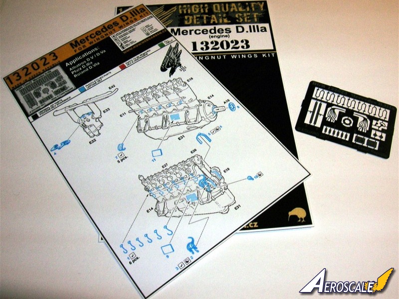
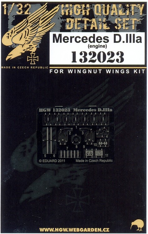
The HGW PE set
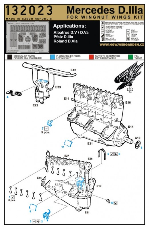
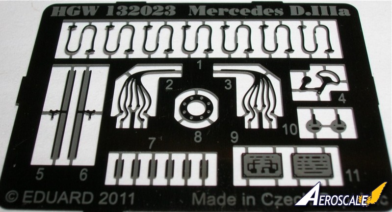
Contains 30 @ nickel coated photoetch items that include:
14 @ Spark plug cable ends to cylinders (2 extras, part #1.
02 @ Magneto harness bands part #5 & 6.
02 @ Sparkplug to magneto harness items part #2 & 3.
06 @ water pipe connections between the cylinders part #7.
02 @ Magneto wire connectors to the starting magneto part #10.
01 @ Circular union boss plate for the forward connections of the upper & lower halves of the crank case part #8.
01 @ Carburetor linkage unit for inflight compensations part #4.
02 @ Datum plates 1 for motor type and 1 for wiring schematics part #9 & 11.
Build Notes
A. The plug cables could use some gel type super glue (Cyano) to thicken the crossections.
B. The for the D.IIIa 170hp carburetor the linkage should have an actuation rod attached running back into the cockpit. In the later 180hp version the actuation rod was done away with and an altitude sensitive version was utilized.
C. The dual magneto connections for the starter magneto need cables to be simulated and run back into the cockpit on the pilot's left. (Painted solder is a good medium here).
D. The Spark plug cable end connections to cylinders should never just be bare metal for operational use. These items like any internal combustion engine had rubber boots to cover / shroud the connections and sparkplugs.
E. The same goes for the sparkplug to magneto harness items. They had similar rubber shrouds. Mostly this was to protect against electrical arching.
Plumbing Colours
The Idflieg document, "Bau und Lieferungsvorschriften für Militärflugzeug"
was amended in May 1917 by Deckblätter Nr.1-67, page 4, Seite 14.
". . .Brown band(s) painted on oil lines every 300 mm (12") with a black arrow indicating the dircetion of flow.
Air pressure lines blue with arrows every 30cm.
Benzin lines white with arrows indication flow direction every 30 cm.
Benzin lines from the tank to fuel pump or directly to the carburetor, white with green rings.
Direction from the fuel pump to the control valve white with red rings.
Direction from the reserve tank or main tank to carburretor, white whith yellow ring.
Direction from the reserve tank to the carburetor is white with blue rings. From the Benzin hand pump white arrows. . ."
When contacting manufacturers and publishers PLEASE mention you saw this review at Aeroscale.
SUMMARY
Highs: This set includes some great details that dress up the basic engines found in the Roden & WNW kits.Lows: The instructions lack some details as to what the parts are. Also you will need to thicken some items to make them look convincing.Verdict: When so many PE companies are excluding 1:32 HGW is forging ahead and giving us some fine details. I do not regret purchasing these items.
About Stephen T. Lawson (JackFlash) FROM: COLORADO, UNITED STATES
I was building Off topic jet age kits at the age of 7. I remember building my first WWI kit way back in 1964-5 at the age of 8-9. Hundreds of 1/72 scale Revell and Airfix kits later my eyes started to change and I wanted to do more detail. With the advent of DML / Dragon and Eduard I sold off my ...
In a similar vein I had an inquiry.
During the last months of the war one about out of every 10 Fokker D. VII airframes went to the front without an engine. There were 3 manufacturers, Fokker, OAW & Albatros. While your stamped info on the prop base appear legitimate, the copper edging was a post war addition. In 1918 each machine went to the front with at least one set of spare parts. Magnetos, propellers and etc. Your best bet is checking with the Belgium aviation museum. They may even have some photos to help you. Wolff was one of at least 4 companies that provided propellers to the Fokker D.VII production. The paddle was the idetifier for the company. Other wise the pitch and length was the same on all props for this type, as it was engine specific. The 160ps = 160hp and was the basic Mercedes Daimler engine for the Fokker D.VII. But was upgraded during the war to 170- 200hp in several variatins in 1918.


Comments