In the aero engine production during WWI the most prolific was Mercedes F1466 & F1466a. No other engine was built and rebuilt more often during the war. Roden has given us 1:32 issue of their Mercedes D.IIIa with PE. It was used on the majority of German aircraft types used for higher altitude operations. Its only equals in the Central Powers were the BMW IIIa and the Austro Daimler 6 at the end of the war.
The Mercedes D.III was based on an earlier development from the company of engineering genius Gottlieb Daimler, the Mercedes D.II, and it featured the same 6-cylinder upper-valve construction. The crankcase was made of aluminum, on top of which were bolted separate steel cylinders and steel cooling jackets fitted over the cylinders. The first version of the Mercedes D.III appeared early in 1914, however it required a series of alterations to perfect it. The Albatros D. type fighters, fitted with the improved Mercedes D.III, were holding superiority of the Western Front. In 1917 the engine was improved yet again: as its compression grew, so did the opportunity to increase its output.
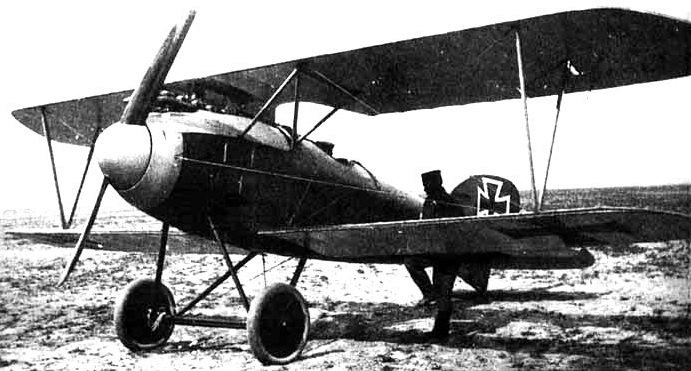
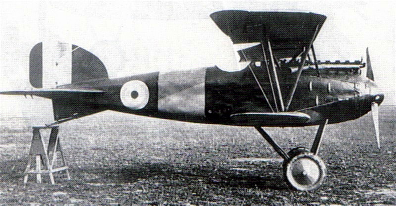
The Mercedes D.IIIa was fitted to the new Albatros D.III - a successful German fighter of 1917. A year later appeared the Mercedes D.IIIaü the 'ü' for 'über' indicated that it was overcompressed. It was visibly different in the shape of the cylinders, and was also fitted with an altitude-compensating carburetor, enabling greater efficiency of the engine at altitude. The Mercedes D.IIIaü was fitted to the Fokker D.VII, which served in the sky of Western Front to the end of the Great War.
Using as a basis the Mercedes D.III, the Austro Daimler 6 was built under license in Austro-Hungary; it resembled its predecessor in both construction and performance.
On the whole, the Mercedes D.III & D.IIIa types may be considered as one of the most successful powerplants of its time. Its great potential, stored up in its basic design, allowed German engine-builders to continually modify and perfect it over a long period, avoiding substantial financial costs on totally new developments in the difficult conditions of the wartime economy, a critical factor for Germany.
The Mercedes D.III -IIIa was installed in a host of different aircraft: the
Albatros D.I - D.Va,
Albatros W.4,
Fokker D.VII,
Albatros C.I - C.III,
Halberstadt CL.II and CL.IV,
Hansa Brandenburg W.12,
Hansa Brandenburg W.29,
Junkers D.I,
Pfalz D.III & IIIa,
Pfalz D.XII and many others.
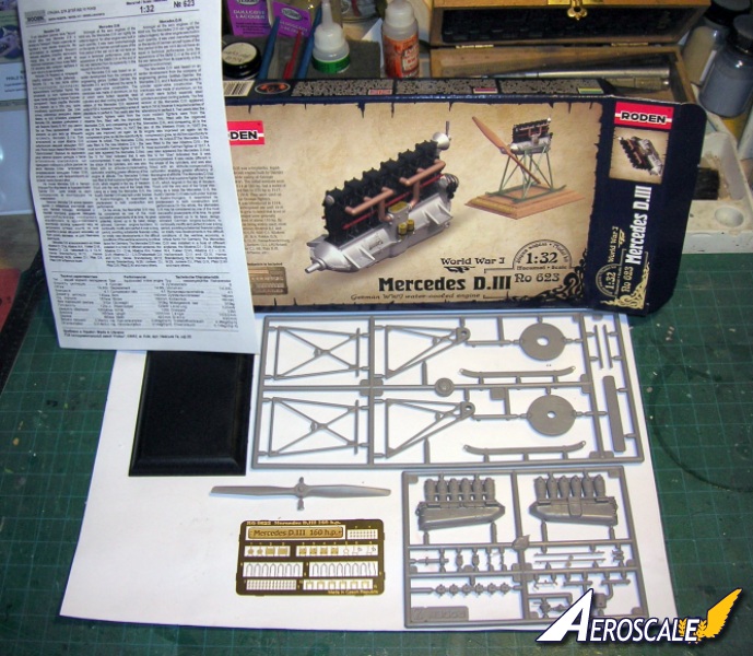
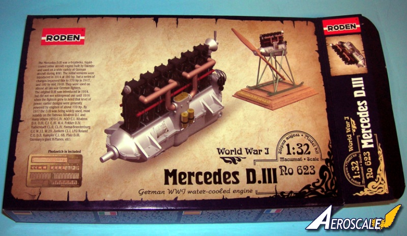
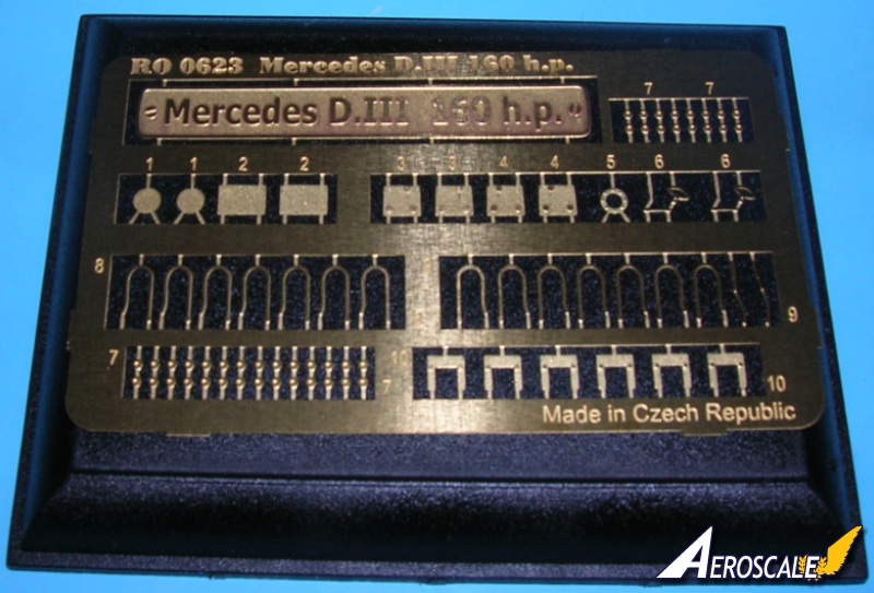
Kit Contents
28 Plastic parts
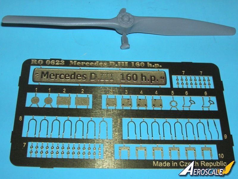
77 Photoetch parts
An excellent modeler once told me that if you detail & treat each assembly like a model unto itself, the whole build will naturally be better than anything that just follows the basic instructions.
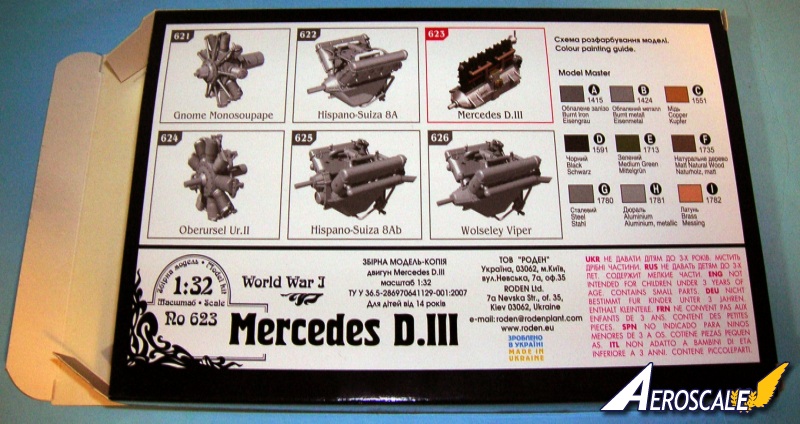
Kit #623 is one of six 1:32 engine sets from Roden. It represents the early Mercedes F1466 D.IIIa motor as it appeared in the Albatros D.III (Johannistahl built machines). The separate sale with inclusion of PE was the first by a mainstream company to do so in 1:32. Roden began selling their large scale motor as separate kits and provided two versions of repair stands to mount them on (One rotary & one inline each). This engine (without PE) was first seen in Rodens Alb. D.I (#614) & D.III (#606) kits. It was also included (somewhat inaccurately) in their Alb. D.III (OAW) (#608). This OAW built type was one of the first to have the later production 170hp D.IIIa motor with some pronounced visual changes.
The early D.IIIa was rated at 170 -175hp is the F1466a Mercedes D.IIIa motor - rated at 170 -175hp variation is almost identical to the D.III 160hp except that ;
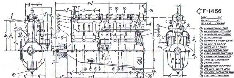
a. Air Pump -- the fuel pressurization air pump is a single upright cylinder model mounted at the front of the engine on top and in front of the first cylinder. It is thin and octagonal from the top view in profile.
b. The concave pistons were replaced with flat pistons that raised the compression. This model was introduced around 1 Feb 1917 for the Albatros D.III. Late in 1917 flat pistons were replaced by domed types. This became the late production D.IIIa 170-180hp motor.
The late D.IIIa was rated at 170 -180hp variation is almost identical to the early D.IIIa, except that;
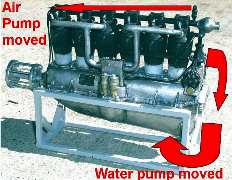
a. Air Pump -- the fuel pressurization air pump is a thicker single cylinder model mounted at the front of the engine on top and at the front of the first cylinder.
b. Late in 1917 flat pistons were replaced by domed types. Domed pistons were the primary method of describing the later 180hp. Being over compressed still by definition makes it an "D.III aü" or ü= uber.
c. The water pump location -- the water pump is moved from the middle of the rear tower to an area down below the crankcase at the bottom of the motor near the oil pump.
As you can see from this, though the kit represents an early production engine it could easily be modified to represent a late production version.
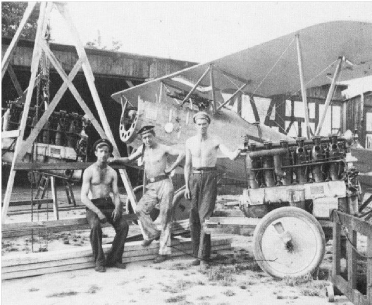
Note: When a motor needed major work it was shipped to one of several repair facilities. For the Germans this was often either at an aviation instruction center or the original parent factory.
It should be noted that the "operational test blocks" for these motors was very substantial wood block and metal tie down strapping with bolts. The framing supplied in the kit represents maintenance supports to work on the motor during overhauls. The motor would never be run up with it in these types of cradles / frames or have a full sized propeller installed while being repaired.
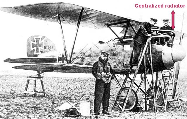
The Mercedes D.III 160hp was outclassed by 1917. The Mercedes D.IIIa 170hp was the standard engine in both of the Albatros (Johannistahl) early built D.III types. Many, many D. IIIa type motors were later rebuilt to the D.IIIaü specs at the airparks as the war progressed. That is why some captured examples had motors with the i.d. designation of D.III 160hp cast into their crankcases. This has caused the misconception that the standard 160hp and 170hp were used later in the war at a time when they had become obsolete. Often these were referred to as 160hp over-compressed engines.
The immediate visual difference in the early Mercedes D.III 160hp / D.IIIa 170hp and its progeny the D.IIIaü 180hp or D.IIIav 200hp are in the rocker boxes above the cylinder jacket heads. On the early D.III and D.IIIa motors the rocker arms (4 Z) are centered on the sides of the rocker box covers. On the D.IIIaü and D.IIIav motor the springs are still centrally located but the box covers are placed further back and the rocker arms are now on the forward leading edge of the same covers.
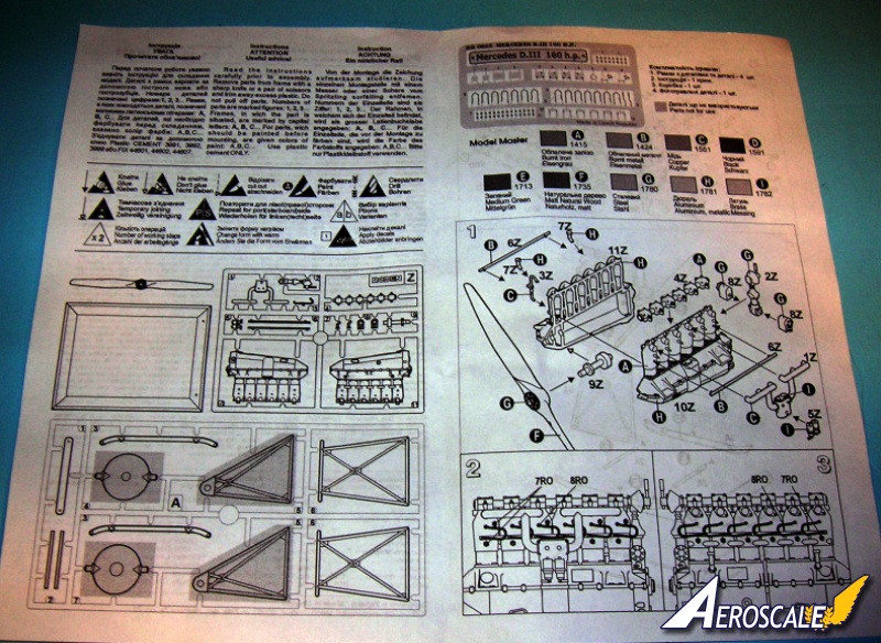
The Build
Step 1. Assemble basic motor plastic parts. The inline motor assembly is specific representation that has pieces for the early Mercedes D.IIIa 170hp (PP 1 5, 6 X 2, 7 X 2 , 8 X 2, 9 11 Z). The upper portions of the cylinders water jackets were the color of blued metal.
Steps 2 & 3. Show the water jacket attachment bolts (7RO X 18) & Sparkplug wires (8RO X 12). These wires tend to be too long and can be trimmed for a better hang from sparkplugs to the conduit pipes (6 Z X 2).
Step s 4 & 5. The overhead rocker boxes (4 Z) from step 1 are detailed with some photoetch that seems superfluous to me. I would leave them off and just add representations of bolt heads in each corner. Also, there are photoetch plates for the motor mount tied down flanges (4RO x 4) and I would rather use some Grandtline nuts and bolt heads to represent these. The photoetch plates work ok if the engine is installed in an engine compartment where the cowling tends to limit close observation. But on a trestle, repair frame or in an aircraft where the cowlings are removed you will want more of a dimensional representation. The Mercedes Daimler (1RO X 2) & Data (2RO X 2) plaques are added only to the pilots left side of the crankcase. Leave the pilots right side plaques for another project. The High altitude carburetor linkage (6RO X 2) were only on late rebuilt model D.IIIa 170hp and all D.IIIaü 180hp motors. If you are doing an early 170hp the carburetor linkage (6RO X 2)dont apply. The end cap for the crank (5RO) goes on as shown. The external oil lines (9RO X 2) are to insure lubrication to the rear of the crank housing.
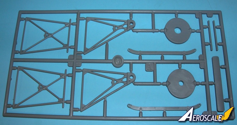
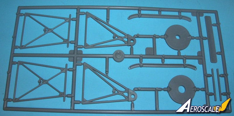
Step 6. This assembles the motor repair stand. The kit has additionally 6 plastic & 1 photoetch parts for an "assembly & repair stand". The stand was used in the shops to:
1. Assembly of new motor.
2. Effect repairs for damaged motors at the factory.
Note: When a motor needed major work it was shipped to one of several repair facilities. For the French this was often either at an aviation instruction center or the original parent factory.
It should be noted that the "operational test blocks" for these motors was very substantial wood block and metal tie down strapping with bolts. The framing supplied in the kit represents maintenance supports to work on the motor during overhauls. The motor would never be run up with it in these types of cradles / frames. And a full sized propeller would not be attached to the motor while on these frames.
I applaud Roden for their attempt at providing a kit with diorama accessories.
Please remember, when contacting retailers or manufacturers, to mention that you saw their products highlighted here - on AEROSCALE
Highs: Nice detailed motor. The inclusion of PE is a good attempt. Lows: Stand is a repair type frame. No prop would ever be attached to the motor on one of these.Verdict: Worth the cost and easy to detail. PE should be standard.
Our Thanks to Roden! This item was provided by them for the purpose of having it reviewed on this KitMaker Network site. If you would like your kit, book, or product reviewed, please contact us.
About Stephen T. Lawson (JackFlash) FROM: COLORADO, UNITED STATES
I was building Off topic jet age kits at the age of 7. I remember building my first WWI kit way back in 1964-5 at the age of 8-9. Hundreds of 1/72 scale Revell and Airfix kits later my eyes started to change and I wanted to do more detail. With the advent of DML / Dragon and Eduard I sold off my ...


Comments