F-16 Fighting Falcon was developed as a result of the Lightweight Fighter Program announced in January 1971. As part of this program two General Dynamics YF-16 prototypes were built and they competed against Northrop?s YF-17 planes. On January 13th 1975 YF-16 has been announced as the winner of the contest, which in the meantime was renamed to Air Combat Fighter (ACF). The first F-16A / Full Scale Development aircraft was flown on December 8th, 1976 and the first operational F-16A was delivered in January 1979 to the 388th Tactical Fighter Wing at Hill Air Force Base, Utah.
Since its first flight Fighting Falcon, also known unofficially as Viper, is constantly modernized and updated. Those modifications however are not clearly reflected in a version number, as only recently the E and F models were introduced and all previous single-seat models were carrying A and C designations (B and D for two-seaters respectively). This is why it is very important to note the block production number, as in case of F-16 it is most important information to properly identify features of the variant.
F-16A/Bs were built in five blocks: 1, 5, 10, 15 and 20. The F-16C/D designation was introduced with block 25. Beginning with Block 30 new engines were installed in Vipers. All previous variants were powered by Pratt & Whitney F100 engines and Block 30 aircraft were first F-16s equipped with General Electric F110 engine. 75% of new Vipers produced for US Air Force were Block 30 GE-powered machines, but remaining 25% still had PE engines - these machines were known as Block 32. After the introduction of Block 30 aircraft to service it became obvious that the air consumption of GE engine, which was significantly higher than this of PE engine, necessitated in redesign of air intake. Beginning with sub-block 30D larger, so called ?big mouth?, air intake was installed. Subsequent production blocks maintained similar designation convention, where block 40 and 50 aircraft were powered by GE engines and featured large intakes, while block 42 and 52 planes were PE-powered and had ?classic? small intakes. Block 40/42 aircraft introduced in 1989 were known also as Night Falcons (unofficially designated F-16CG/DG) because of their enhanced night/all-weather capabilities achieved by installation of LANTIRN pods. One feature only present in Block 40/42 aircraft is a Wide Angle Raster (WAR) HUD capable of displaying sensor imagery. Block 50/52 feature, among other updates, upgraded radar and Improved Performance Engines, the F110-GE-129 for the Block 50 or the F100-PW-229 for the Block 52. But the HUD in Block 50/52 aircraft is the same standard device as in all F-16 prior to Block 40.
In May 1993 deliveries of Block 50D/52D began. These aircraft, unofficially known as F-16CJ/DJ have added capabilities, which allow them to perform Wild Weasel (SEAD - Suppression of Enemy Air Defense and DEAD - Destruction of Enemy Air Defense) missions thanks to a full integration of HARM missile avionics/Launcher Interface Computer (ALIC) and associated systems / pods. All but the earliest Block 50 planes have been upgraded to Block 50D standard.
New Academy kit, while only listing Block 40 and 50 on the box, was earlier advertised as including parts for Block 40, 42, 50 and 52 aircraft. We'll soon see what is actually in the box...
While this article is not meant as a comparison between Tamiya F-16CJ and Academy F-16CG/CJ kits, it's difficult to avoid some comments to this effect. I will however do my best to evaluate Academy product on its own as objectively as possible.
The kit
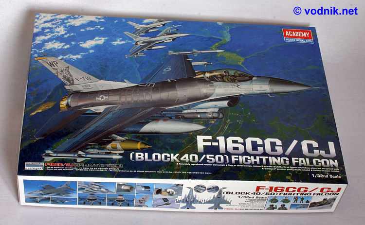
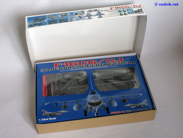
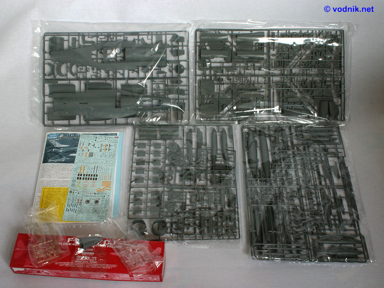
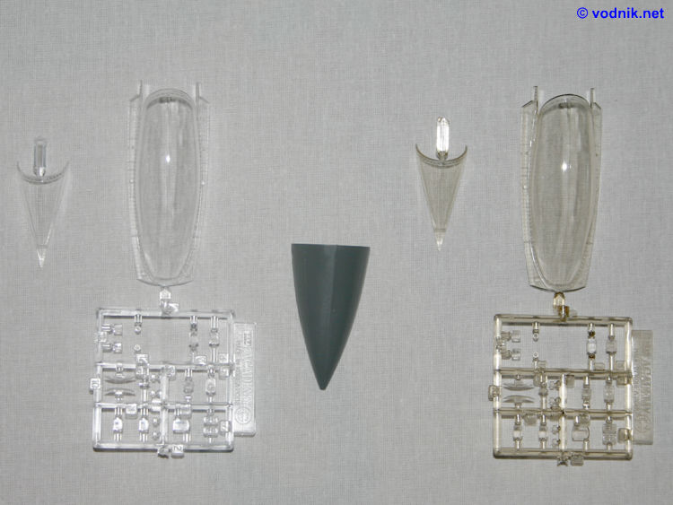
The kit comes in a large box with a decent (not a piece of art) picture of 35th Fighter Squadron "Let's Roll" aircraft on the lid. The box is similar size as Academy's F/A-18C kit box, although about an inch thinner. Underneath two lids (the inner one with clear "windows") is a small card box and dark grey plastic sprues in plastic bags (two sprues per bag). There are four plastic bags in the box with 7 large and one smaller sprues inside them. In the small card box are clear parts in two versions - one of them tinted, and a radome part. On the bottom of the box is a bag with 28 page A-4 size instruction booklet and two quite large decal sheets plus a tiny additional sheet with two colorful badges. No metal parts of any kind are included.
Markings on decal sheets, printed by Cartograf, are provided for six aircraft, but in instructions units are identified only based on the tail marking, so for some aircraft the squadron ID is not given, just the higher level unit number:
1. F-16CG, Block 40E, 89-2013, 8th Fighter Wing (this one is from 35th Fighter Squadron), Kunsan AB, South Korea, September 2004 - with nice multicolor "Let's Roll" emblem,
2. F-16CG, Block 40E, 89-2003, 35th Fighter Squadron, Kunsan AB, South Korea, August 2004,
3. F-16CG, Block 40E, 89-2020, 51th Fighter WIngs, Osan AB, South Korea, September 2004,
4. F-16CJ, Block 50P, 92-3895, 5th Air Force, Misawa AB, Japan, February 2005,
5. F-16CJ, Block 50P, 92-3901, 35th Fighter Wing, Misawa AB, Japan, September 2004,
6. KF-16C, Block 52D, 93-4067, Republic of Korea Air Force (RoKAF).
Additionally included is a whole set of generic grey numbers to create any RoKAF F-16 jet markings.
On decal sheets we also get full set of very well printed stencil decals for the aircraft and all external stores. Print quality is excellent with all markings printed in perfect register. Decal film is very thin and glossy and generally the decals seem to be the true highlight of the kit.
Molding quality is good, although I noticed some flaws. There is minor amount of flash on some parts. There is quite a lot of ejector pin marks and while majority of them will be hidden after assembly, I still found quite a few that will require attention. They are for example on inner sides of engine exhaust (close to the edge of exhaust, so clearly visible from outside), inside air brake halves (only important if you want to position them open), on back sides of all landing gear doors, on NLG wheel and strut, on MLG struts and well components, on AIM-9 missiles and on some small detail parts. I've found only one sink mark on a small detail part and it is easy to fill and eliminate.
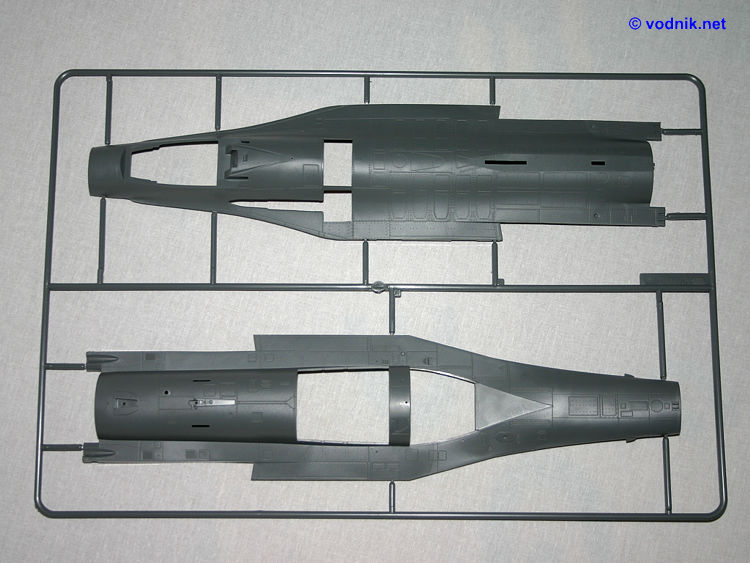
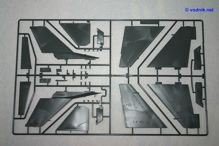
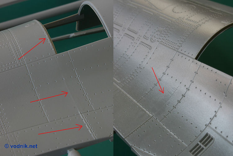
On the upper and lower fuselage halves are quite noticeable seams, which most likely show where the mold is split to allow for the release of two-seat variant in the future. The problem is particularly clearly visible across the upper fuselage part, behind the gun bay. There is a noticeable step where parts of the mold meet and removing it without destroying surrounding details would be impossible, as it goes along the line of rivets. The whole surface of fuselage parts is slightly rough, so sanding and polishing the part in one place (e.g. to remove the mold split seam) will inevitably leave it smoother than surrounding plastic.
The engraved surface details - panel lines and rivets - are generally very nice, albeit shallow, but in some areas lines get soft and almost disappear. Such areas are the sides of the rear lower fuselage, but also the very top of the upper fuselage. Two panel lines on front fuselage on both sides of the glare shield look like scribed by hard without a template - they are soft and uneven. Some rescribing would probably be needed to make sure some of that lines don't disappear under the first coat of primer or paint.
In my kit I noticed one missing part - number B13 (bad luck?...) - a static discharger for the wing trailing edge. It was not in the sprue plastic bag, so it must have been broken off of the sprue before it was put in the bag. Luckily there are three spare parts B13 provided in the kit.
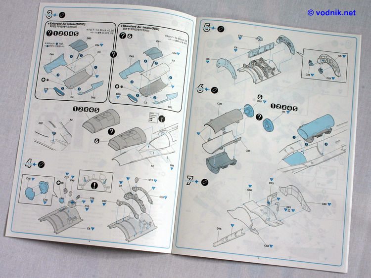
The split of parts in Academy model is quite typical for modern jet kit with two main fuselage parts (upper and lower), wings in two halves (upper and lower) with separate flaperons (the only separate flight control surfaces in the kit), two stabilators (one piece each) and vertical tail in two halves. Additional parts building the main aircraft structure are: air intake (two versions - NSI small mouth intake for Block 42/52 planes and MCID large intake for Block 40/50 aircraft - both composed of three outer parts plus separate intake lip and intake duct parts), fuselage end section and exhaust nozzle (again two versions - for P&W and GE engines - both multipart subassemblies), one piece radome and the end part of the vertical tail base. For the tail base we got two options - standard short tail and long tail with parachute housing (the part representing folded parachute is included). The long tail parts are not used for any of the planes for which we get decals, but are still shown in instructions with a note that for example Hellenic AF use such tail.
The gun bay can be fully open as three panels covering it are separate parts, and the complete Vulcan cannon with ammo drum is included.
No weight is provided or mentioned in instructions - let's hope this model will not be a tail sitter when assembled without it.
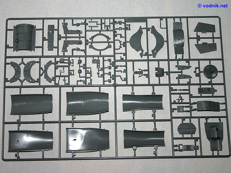
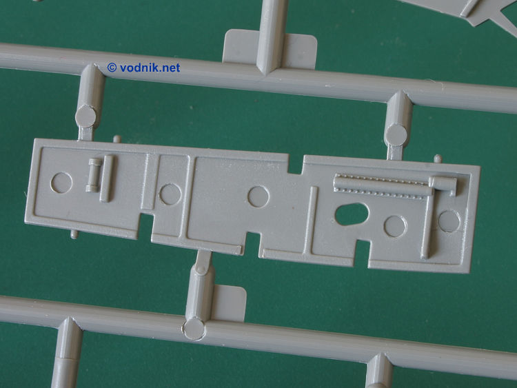
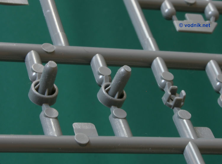
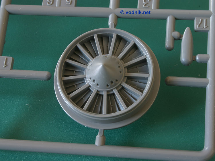
There is no engine provided in the kit, but complete air intake duct is present (made from four parts, so quite a lot of work may be needed to eliminate all seams inside it). The front two section of intake duct are provided in two versions - for MCID and NSI intakes. Also compressor face part is provided in two versions - for F100 and for F110 engines. The compressor face for P&W engine (part C65) looks like it is missing a tip part. By the look of it I would swear that there should be a separate tip part included for the center cone (see photo), but it is not present in the kit and not mentioned in instructions.
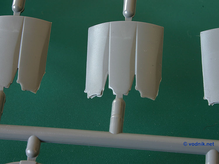
As mentioned earlier two exhausts are provided, both with afterburner section details and with the rearmost fuselage section (four parts for each version). GE F110 nozzle itself is composed of six parts, but for P&W F100 there is ten parts to build two layer nozzle.
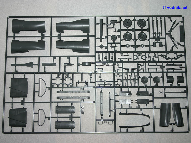
Main cockpit tub structure is in one piece with quite nice side console raised details molded on. Only the back wall of cockpit and two parts with some details for cockpit walls (inner fuselage sides) are separate. Additional parts are provided for main instrument panel and three smaller consoles. All analog instruments have raised details on their faces. For two MFD screens Academy provided multilayer sandwich parts - main instrument panel provides only frames to which two clear rectangular pieces are attached. Behind clear parts attached is another part, this time opaque, with display data decals applied on it. It remains to be seen how this would look like once assembled and painted. To the featureless bottom of cockpit tub attached are rudder pedals provided as one piece (without any mechanism attached to them). The control stick on a separate base is the only part to be attached to cockpit consoles, and the thrust lever is provided to be attached to the cockpit wall. No details are provided for the are behind the ejection seat, just a couple of small details for the canopy actuator parts.
The ACES II ejection seat is composed of eight parts and seems to be reasonably accurate and acceptably detailed, although not particularly impressive in this large scale. Seat belts are molded on and don't look good.
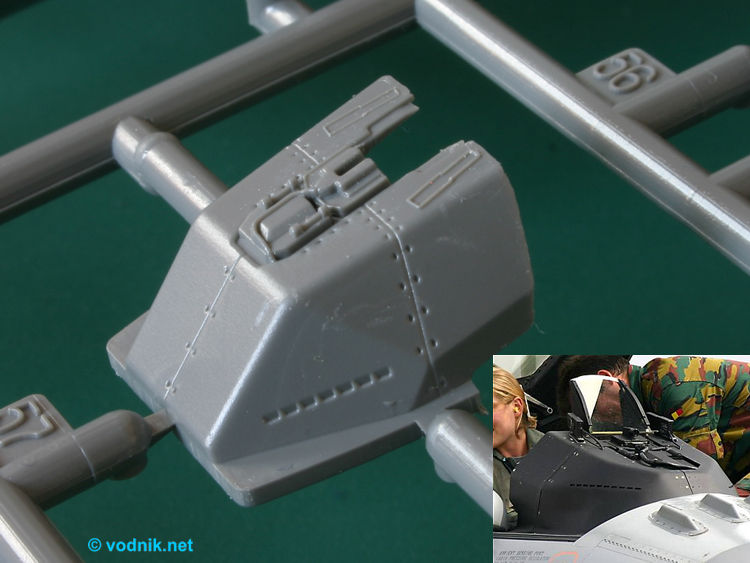
Glare shield is a separate part and two types of HUD are provided - WAR and standard narrow one. Each HUD is composed of a couple of clear and grey plastic parts. Aside from HUD also several other tiny detail parts are attached to the top of glare shield and there are de-fogger vent details molded on glare shield sides (missed by Tamiya).
Two sets of clear canopy parts are provided - one not tinted and one with yellow-brown tint. Canopy parts have mold seams running along them - inevitable to achieve proper bulbous cross-section shape. Obviously they will require some work to remove, but as this is now standard feature in majority of modern jet kits, most modelers should already have some practice in dealing with it. Additional (opaque) parts are provided for bottom frames of the canopy to be glued inside clear part, but they are completely featureless and don't provide any additional details of canopy seal and latches (only a few ejector pin marks). To these frames attached are two separate handles. Canopy can most likely be attached open or closed, although the open position is not actually shown in instructions. On the other hand we get 6 piece boarding ladder in the kit, so it is rather obvious that open canopy configuration is possible. In open position canopy must be glued in place as there is nothing what could hold it in place without glue.
Nose landing gear well walls are molded on one of the air intake duct parts. Aside form some basic shapes of structural elements molded on inside, the NLG well is completely devoid of any details. No surface details, no rivets, no cables, no pipework. As I mentioned earlier no metal parts are provided in the kit, so obviously all landing gear struts are molded in plastic. The NLG strut unit (incl. all actuators) is composed of six parts. The wheel is plastic and molded in one piece (there are three small ejector pin marks on one side). The NLG well door has details molded inside (plus a few shallow ejector pin marks) and we get two versions of this door: one for USAF jets (fitting to the MCID intake parts) and one for RoKAF machine (for NSI intake). Parts look identical on sprues, but the curvature is just very slightly different. Two detail parts for hinge and door actuator are provided and of course two landing lights are also included (each composed of two parts, one of them clear).
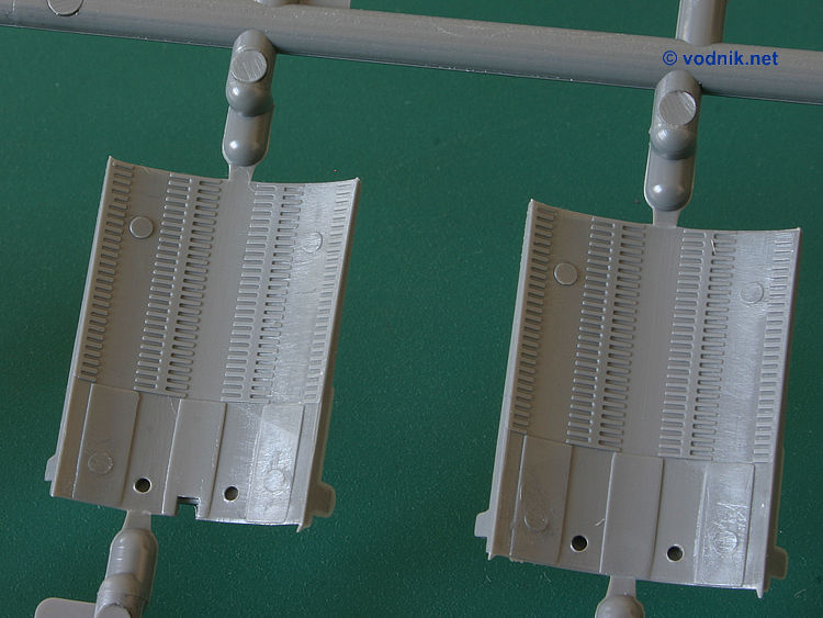
Main landing gear well is better detailed than NLG well, although all cables and pipes are omitted. Six major parts constitute the main well structure and there is quite a lot of rather big ejector pin marks on them. Getting rid of them all can be a really daunting (if not impossible) task, considering how they are located between structural ribbing. Surface details are very limited with only some of the rivets represented. Nice separate parts dress up the well interior. Actual MLG is made of 10 parts (total for both sides) plus two wheels - each in two halves. The level of detail on MLG well doors is the same as on NLG door and also here we get a couple of ejector pin marks. Each door is attached to the fuselage with three small hinge and actuator parts.
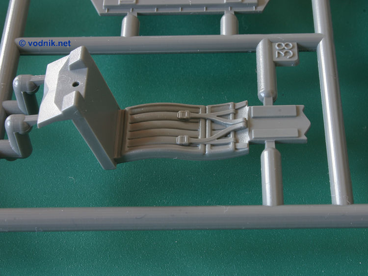
The M61A1 gun is provided complete with the ammunition drum (total of 20 parts, including the gun bay walls) and can be displayed if three separate parts of aircraft skin (representing four real plane panels) are not attached.
The radome can be displayed open or closed (but is not moveable once installed). Six piece radar unit is provided. The radar antenna can be set in any azimuth position, but cannot be moved in elevation.
The speed brakes can also be positioned open or closed and we get actuator detail parts to install inside open brake halves.
I already mentioned before that the only flight control surfaces provided as separate parts are flaperons and for them there is no hinge mechanism provided, so they must be glued in chosen position.
Two types of "bird slicer" IFF system interrogator antennas are provided to be installed in front of a canopy. One type is for USAF CCIP machines, the other type is for RoKAF plane. For RoKAF aircraft we also get a set of ASPJ (Airborne Self-Protection Jammer) antennas.
Finally to add small details to the airframe we get a number of various antennas, static dischargers, Pitot tubes, AoA probes and navigation lights (in clear plastic).
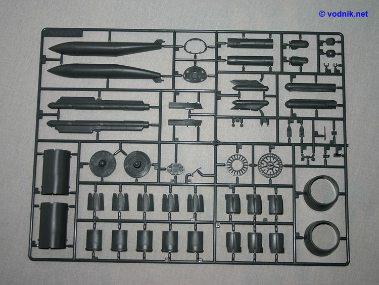
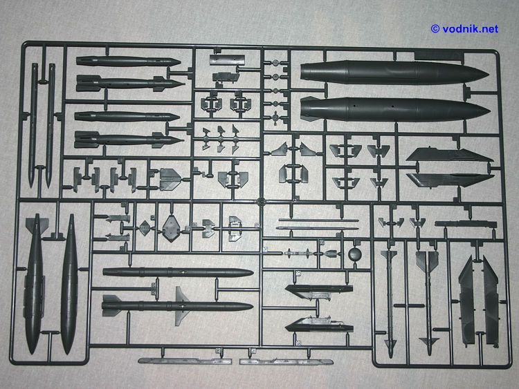
External stores included in the kit are:
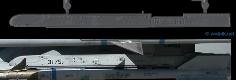
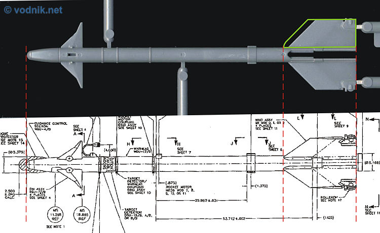
- two AGM-88 HARMs (each composed of six parts) with two LAU-118 launchers (four parts),
- two GBU-31(V)1 JDAMs (four parts each),
- two TERs (four parts)
- four GBU-12 Pavewey II bombs (7 parts),
- AN/ALQ-184(V)1 ECM pod (two parts),
- two AIM-120B AMRAAMs (10 parts) or two AIM-120C AMRAAMs (10) - some parts are common so you cannot build four AMRAAMs,
- two AIM-9L/M Sidewinders (5 parts),
- two AIM-9X Super Sidewinders (7 parts),
- AN/ASQ-213 HTS Pod (2 parts. For some reason two pods are actually provided on sprues - one on sprue E and one on sprue H, with the latter one marked in instructions as "unused part",
- AN/AAQ-14 LANTIRN targeting pod (8 parts) with appropriate pylon in two versions (for MCID and NSI intakes),
- AN/AAQ-13 LANTIRN navigation pod (4 parts) with pylon (again in two versions),
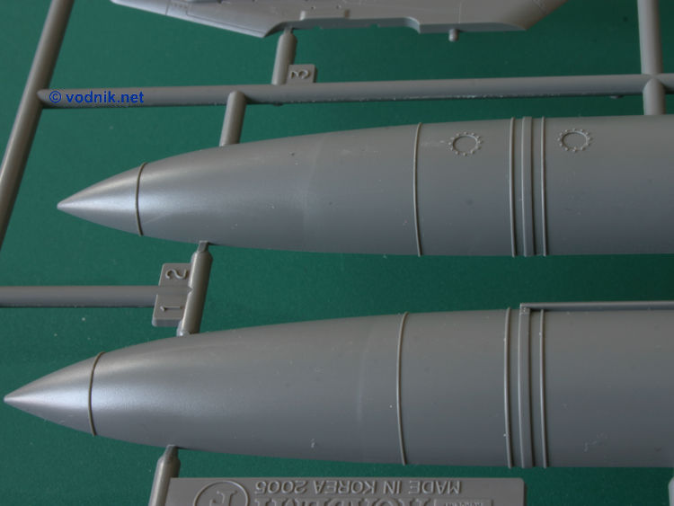
- two 370 gal. wing fuel tanks (3 parts),
- one 300 gal. centerline fuel tank (2 parts).
- two pylons for STA 4 & 6 (three parts),
- two pylons with sway braces for STA 3 & 7 (4 parts),
- two STA 2 & 8 pylons (one part),
- one centerline pylon with sway braces (3 parts),
- one AN/ALE-50 Towed Decoy System pylon,
- four LAU-129 launchers (one part) with nice rail details molded using the slide molding technology.
All stores are well detailed with appropriately raised or engraved details. No clear parts are provided for external stores. Most missiles and bombs have half of their fins molded with one part of fuselage and the other half as separate parts. Only AMRAAMs have all their fins separate to allow for assembling two missile versions using the same fuselage. GBUs have separate laser seeker heads (with ugly ejector pins on the tip of each) and some of the missiles have separate tail tips for better detail definition. All pylons and weapons must be glued to the airplane and small pins and holes help to set them in the right place.
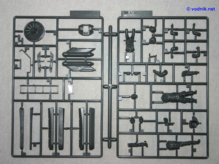
And finally to crew our new plane we get three figures - one sitting pilot with two optional left arms, two right arms and two heads in different positions (unfortunately both heads have their oxygen masks on - it would be nice to have one without a mask); and two standing ground crew members (with two optional heads for one of them).
Parts marked in instructions as "unused" include one complete AN/ASQ-213 pod, three static dischargers and two trapezoidal clear parts, which I cannot identify.
The accuracy
I must admit that I?m not a F-16 expert, so I won't even try to provide detailed analysis of accuracy of Academy Viper kit. I will just list a few features and problems, which attracted my attention. The list below is definitely not complete and it is also possible that I may not be right in some of my observations.
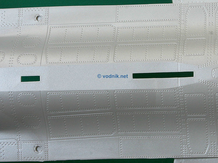
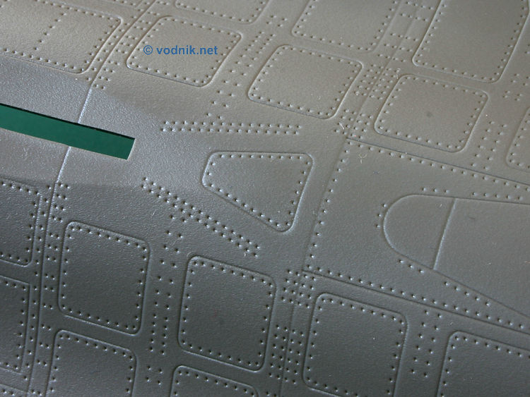
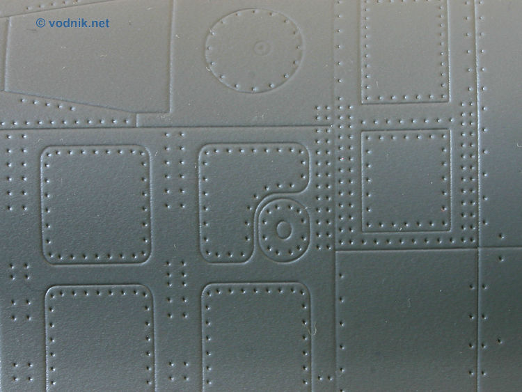
The Academy kit should be very well received by "true rivet counters". There is plenty of rivets to count on airframe and external stores, most of them represented by tiny holes although they are also some raised rivet details e.g. on fuel tanks. This is probably the most noticeable difference between Tamiya and Academy model: Tamiya restricted the number of rivets to those more prominent ignoring many of those barely visible ones, while Academy obviously tried to depict them all. Whether it is a good or bad thing depends on preferences of individual modeler. One area where it is most visible is vertical fin, where Academy filled big central panels with rivets. These rivets are indeed there on the real plane, but they are usually hardly noticeable. In Academy model bolt heads and flush rivets on aircraft skin are represented by exactly the same size pinholes. On the other hand Academy didn't include any rivet details inside landing gear wells (while there is plenty of rivet detail there in Tamiya kit and obviously on real aircraft).
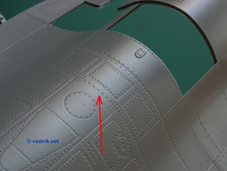
For those who remember that the most well-known error of Tamiya F-16CJ kit were incorrectly reproduced panels on the back of the upper fuselage, on both sides of the tail fin, I have good news - Academy almost nailed this area with correct asymmetrical panels layout. But... unfortunately there are other panels on upper fuselage that are wrong. One such panel is just in front of the tail fin base - trapezoid shaped panel there is correct size for aircraft with strengthening patches attached, but these patches are not included in the kit (what is an inaccuracy for Block 40 machines, like those featured on decal sheet!). There are even two double lines of rivets added on model surface on both sides of this panel - corresponding to lines of rivets visible on strengthening patches in this area. For block 50/52 machines this panel should be oval and smaller.
Another not fully correct panel is to the front and starboard side of the IFR receptacle door. There is one L-shaped panel with smaller oval panel squeezed in a corner of it. The problem is that the smaller panel on Academy model is in the lower right corner of bigger panel, and it is correct only for block 50/52 aircraft, while it should be on upper right corner for all earlier types.
This is just a couple of panel inaccuracies I noticed - unfortunately it is quite likely that there is more. But to put the information in the right perspective - Tamiya F-16CJ model has this two panels mentioned above reproduced accurately for block 30 or earlier machine, but also not accurate for Block 50!
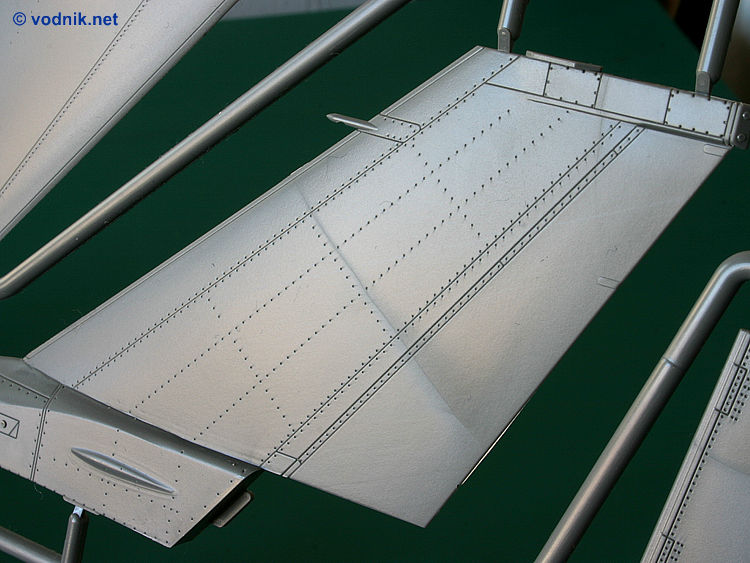
The only good quality scale plans of F-16 I have are those from the Daco "Uncovering the Lockheed Martin F-16 A/B/C/D" book, but they are known to be inaccurate in a few areas. For example on these plans the vertical fin and its base is too large, horizontal stabilator outline is not quite good and some panel lines (e.g. those asymmetrical ones near the fin) are not correct. I compared the model to those plans (scaled up to 1/32) anyway and apart from the mentioned areas, everything fitted quite well. And to see how well horizontal and vertical tail surfaces are portrayed, I compared them to parts from Tamiya model - the size and outline was the basically same (+/- 1mm).
I noticed that on Tamiya model's wing root surfaces, on top and bottom, are three very small bulges - one on upper surface and two on lower surface. I noticed such bulges on various F-16 photos, but on other photos they are clearly not there. I have no idea which aircraft should have them and which should not, but in Academy kit these bulges are not there, what may be inaccurate for at least some of versions depicted.
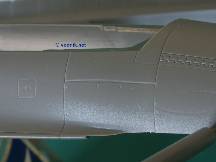
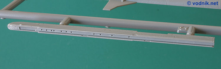
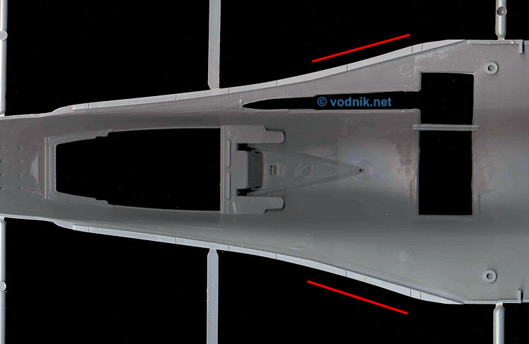
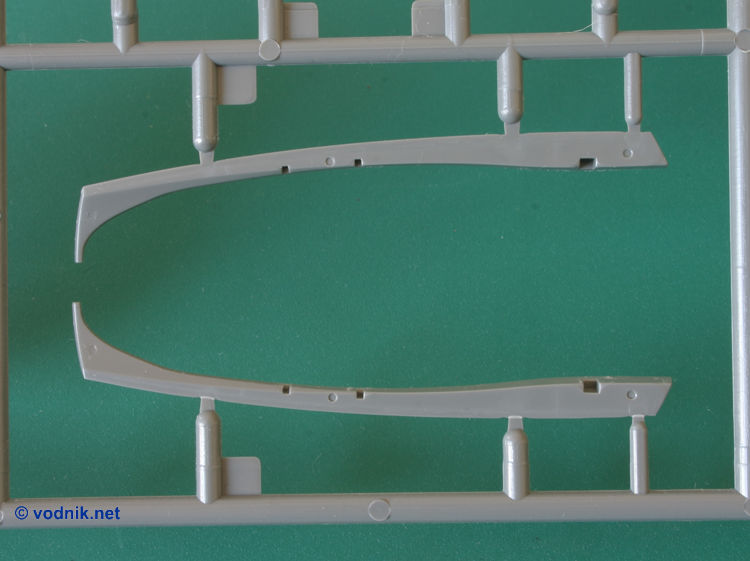
While looking at plans and pictures and comparing them to fuselage parts of Academy kit I realized that there is something slightly wrong in the shape of LERXs. The outline seems to be a little bit too straight-lined in the area behind cockpit. I have shown this part of the model on one of the photos, so you can decide yourself whether you see any problem there.
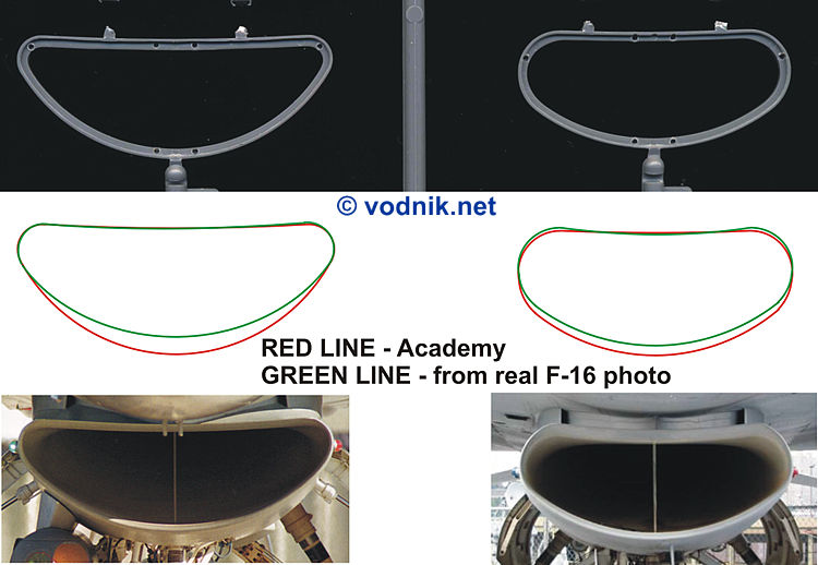
One quite noticeable inaccuracy is in the contour of air intakes. Neither NSI nor MCID intakes look fully right, with the latter being particularly incorrect. Take a look at photos.
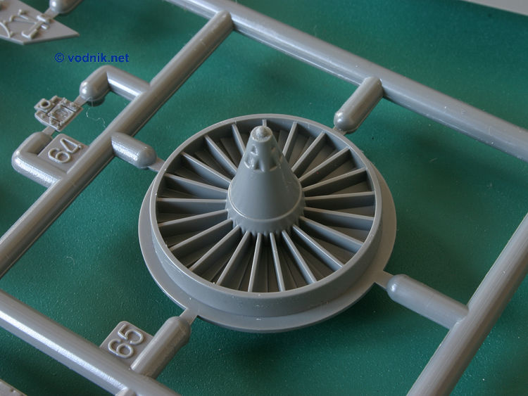
Academy provided just one set of engine fan faces and exhaust nozzles for P&W powered planes and one set for GE powered birds. This is not quite correct, as different versions of GE engines are used in Block 40 and Block 50 Vipers and the same is true for P&W engines in Block 42 and 52 aircraft and there are differences between fan faces (both in GE and P&W engines) and nozzles (only in P&W) between versions. The P&W fan face in the kit looks like acceptable representation of F100-PW-229 engine part (so correct for Block 52), although the tip of the center cone seems to be missing, but the GE fan face does not look good for any GE engine face I was able to find on photos. The center cone diameter seems to be too large for any type. For majority of modelers the flaws in fan face details are of course completely irrelevant, as this part is hardly visible. The engine nozzle of P&W engine is not detailed enough to be certain which version Academy designers planned to depict, but the outline of turkey feathers looks more like in F100-PW-220 parts with two little extended tabs at the end. That would make them not quite accurate for Block 52 aircraft, but as I already wrote nozzles are not detailed enough for it to be any real problem.
On the back of the canopy one part is missing - there should be a bar running across the canopy base behind the ejection seat rails. This part is not included in Academy model, but it looks like it was actually supposed to be there, but someone forgot to include it! There are two open slots molded on canopy lower frame parts D57 and D58 - in the exact spot where mentioned bar should be - but nothing is given to fill these slots...
One accuracy problem, which I have heard about long before the kit was actually released, is the shape of the glare shield. Unfortunately Academy was not paying attention to what modelers say and the part in the kit is as bad as it was on the sample model shown several months earlier. There are well done de-fogger vents (which were missing from Tamiya model) and other details on the surface of the part, but the overall contour of the shield is just wrong.
The layout of instruments and raised details on all cockpit panels is quite accurate, but the control stick does not look that good as it is too flat and lacks some details.
Details of ejection seat are generally accurate, if somewhat simplified and molded on seat belts look rather bad. All in all the cockpit is nice, but it could be much better in this scale.
External stores are very well done. Some features are nicer and more accurate than in Tamiya model - for example weld seams on fuel tanks are represented as raised lines and AMRAAM missiles have more accurate diameter (those in Tamiya kit are just slightly too thick). I would love to say that LAU-129 launchers are much better in Academy kit with their very nice rail details molded on (slide molding), but unfortunately the profile of the nose of the launcher is not correct. Some details of JDAM bomb are also more accurate than in Japanese kit.
One missile that is undoubtedly inaccurate is, surprisingly, well known and documented AIM-9L Sidewinder! Tail fins are noticeably too short what makes the rear of the missile look odd.
VERDICT
The kit is a mixed bag. The price of Academy big Viper is about 70% of the price of Tamiya kit (using prices at Lucky Model for comparison), so it is not surprising that it does not offer exactly the same quality. There are some molding and tooling quality and engineering issues visible in Academy model, like some poorly defined panel lines, ejector pin marks or the ugly seam running across the fuselage, but in other places there are beautifully rendered details present. Also while some areas were evidently carefully researched and are very accurate, in other places some noticeable inaccuracies are present. It is not quite possible to fully accurately depict any of advertised Block versions. Some of incorrect and missing features are:
- for block 40 and 42 planes there are no strengthening patches on the aircraft skin,
- for block 50/52 the shape of panel in front of the tail fin is incorrect,
- PE engine nozzle is more accurate for Block 42 (F100-PW-220), but fan face is more accurate for Block 52 (F100-PW-229).
These are minor problems, but they show that Academy took some shortcuts in the kit.
Generally if you are not an accuracy freak and don't mind some minor surface blemishes on your model (what effectively means you are one of 95% of all modelers...), then for you the Academy model is a good choice. For acceptable price it offers great selection of external stores, excellent "aftermarket quality" decals and quite good overall level of details. It should be easy to build and will definitely look great when finished. Inclusion of three figures is definitely also a plus.
If however you care for accuracy in your models and expect very high manufacturing quality from models in this price range, then you may be disappointed and for you the investment of extra money in hi-tech Tamiya Viper may be a good idea.
Recommended with reservations!
Many thanks to Raymond Chung of Lucky Model for the review sample!