

1⁄48Finnish Buffalo
10
Comments
Introduction
In the 1970s Tamiya released a modern 1/48 model of the tragic Brewster Buffalo. It was an amazing model for the era, detailed, good fit, decals for USN, USMC and RAAF. As modelers became more discriminating the flaws of the kit began to stand out. Classic Airframes has stepped in with modern new models, not only of the aforementioned versions, but the only successful Buffalo, those flown by Finland.
History
Builders of carriages and coaches, Brewster diversified into airplanes. Brewster's XF2A-1 prototype first flew in December 1937. The F2A-1 Buffalo was a very modern aircraft at the time but flawed. An improved version was needed and 44 of the original 54 were denavalized, declared surplus, and sold to Finland as the Brewster Model 239.
Over the Pacific in 1942 with the Americans, Australians, British and Dutch, the Brewsters combat performance was summed up by a Marine pilot after the Battle Of Midway, who told his superiors that any pilot assigned to a Buffalo should be considered lost the moment he left the ground! However, from 1941 through 1944 the 44 Finnish Buffalos shot down 496 Soviet and German aircraft, loosing only 19 Brewsters, an incredible kill to loss ratio of 26:1! The top-scoring Brewster pilot was 75 kill ace Hans Wind, 39 kills he claimed in B.239s, 26 of his kills were flying BW-393. Fifty-six kill ace Eino Luukkanen scored seven more kills in BW-393. BW-393 is credited with a total of 41 kills, the most victorious airframe in history!
The Kit and Instructions
Classic Airframes is praised by Buffalo aficionados for the research and attention to detail they put into making these accurate models, e.g., the 1930s era U.S. aircraft design of washout of the lower wingtips, for example.
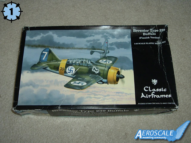
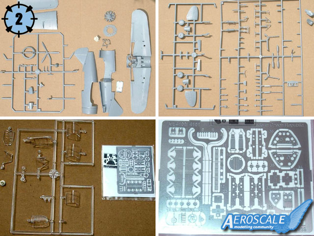
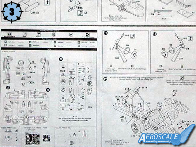
Packing is a flimsy top opening box with nice box art (that is the condition of the box when it arrived - see picture 1). The box is fully packed with 4 plastic sprues, a photo-etch fret and a film set, 4 resin parts, and a black & white color and marking guide for the generous decal sheet (picture 2). Though the instruction sheet is crisply illustrated, some steps are ambiguous (picture 3). The part sprue illustration has pencil check marks confirming the parts are in the box. Those pieces not for this particular Buffalo are shown Xed out. You will be left with spare canopies, USN seat, tail cone, floatation gear, and other odds and ends (anyone need these?). Bombs and P/E racks are available with the note that no photographs show Finnish Buffalos affixed with them. Classic Airframes advises in most steps to dry-fit and check alignments, and ensure previous gluing is dry before proceeding to the next part - for a reason.
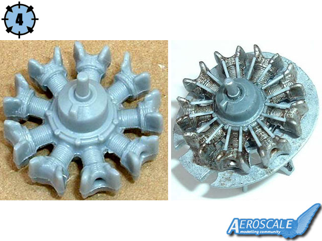
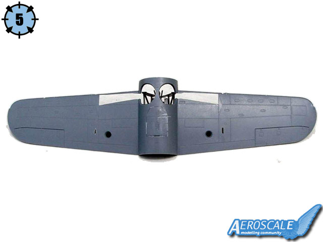
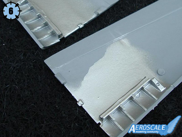
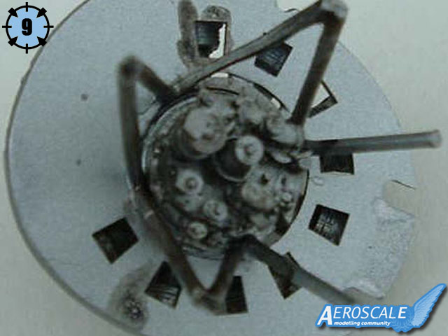
The plastic parts are almost flash-free, heavy & thick, blemish-free with shallow recessed panel lines. The rivets on the landing gear are a bit soft. The surface is very smooth and won't need any additional work. This is my first limited-run kit and I understand this is unusual. The detail parts are nicely done with an exception: the Wright 1820G-5 9-cylinder radial engine looks good but the pushrods will have to be made out of stretched sprue or wire. It is marred by a gapping hole where the plastic did not flow, fortunately not visible (picture 4). Twenty steps guide you to a paintable model. You start with the single-piece bottom wing-fuselage bottom, deciding if you want the window on the bottom of the fuselage or the metal plating it was replaced by. I chose the latter and was worried by the fit of these first two parts (picture 5)! Next, glue the resin upper wing structure (visible in the landing gear well) onto the top wing halves (picture 6). Spring ahead to step 19 and fill the starboard landing gear light as B.239s only had one. Now is also a good time to open up the wing gun shell ejection ports.
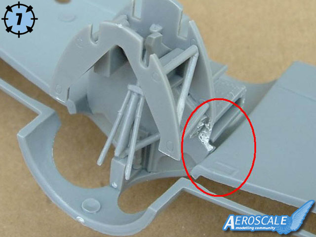
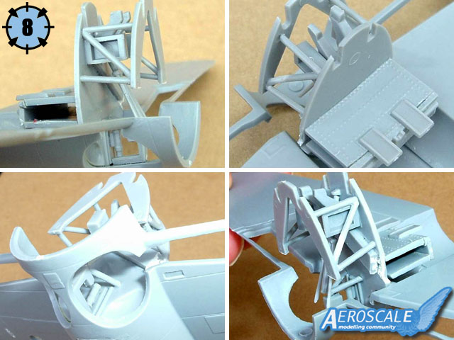
Next you build a complete interior from the engine to cockpit. These mount into the wing-bottom fuselage piece. Then the fuselage is glued around it. Here are major fit problems. The mounts for the engine, landing gear retraction apparatus and nose guns attach to the bulkheads and firewall, but there are no holes, only molded attachment points. The mounting tubes have no pins in the end to mount into holes you might drill. None of the parts have male/female attachment points. All the mounts are scale-thin and thus fragile. Part D5, the spent cartridge chute interferes with mounting the top wing. (pictures 7 and 8). Step 4a builds the cockpit floor. Read carefully as you must cut a piece off. I cut the wrong part. Step 5 is assembling the engine and resin accessory to the firewall. The engine and engine mount is much smaller than the firewall hole it mounts through (picture 9). Dry-fit and check alignments!
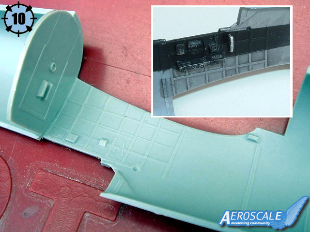
C.A.s sequence is to partially assemble the cockpit rear bulkhead and decking into the right fuselage half, then mount it to the completed wing assembly (containing the nose gun and landing gear retraction system), and insert the engine. Dry-fit and check alignments! This was very cumbersome for me. C.A. molded fine structural detail into the fuselage cockpit areas, and alignment grooves for the firewall and three bulkheads. The problem is that these fine grooves are useless for actually seating the parts! Thank goodness for superglue! Dry-fit and check alignments! Twenty-two plastic, P/E and film parts comprise the extensively detailed cockpit sidewalls. Not all pieces have guides molded into the fuselage to show where the pieces actually mount. The P/E throttle and mixture levels are so small (not quite 1mm) they are virtually usless. Consider replacing them with wire or plastic rod (pictures 10 and 11). Jump ahead to step 20: mounting the antenna mast (D42). There is a faint outline scribed near the top front of the right fuselage half as a mounting guide, consider drilling it out slightly.
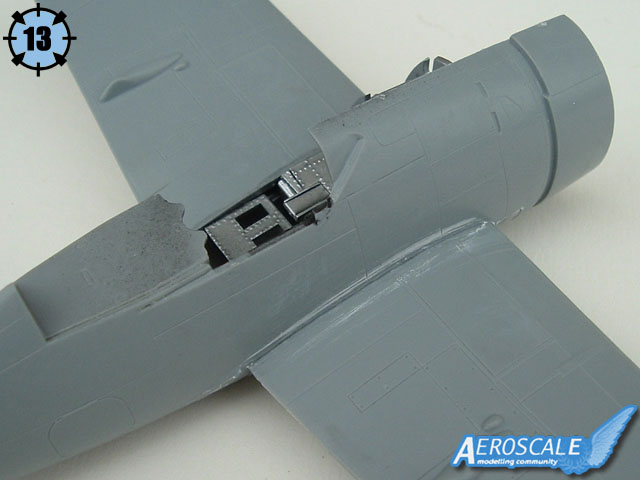
Step 10 was very frustrating. Mount the P/E seatbelts to the seat and add the control stick (which seems far too tall) and a side handle - all straight forward. The bad part is mounting the beautiful instrument panel and rudder pedal/center consol assembly. There is nothing in the fuselage to hint at where to affix these. The panel is too small to fit to the fuselage contour (maybe it did not in real life) and the rudder has only the tiny tube to affix to the fuselage side (picture 12). When the fuselage halves are mated (step 11), my panel and rudder pedals are off-center. Also, it is not clear where parts D34 and D35 go. I thought they were the gun sight, but now think it is the compass. The engine seems to set far too deep within the cowl. Test-fit the tail wheel into the opening on each half; I did not and was sorry later. Dry-fit and check alignments!
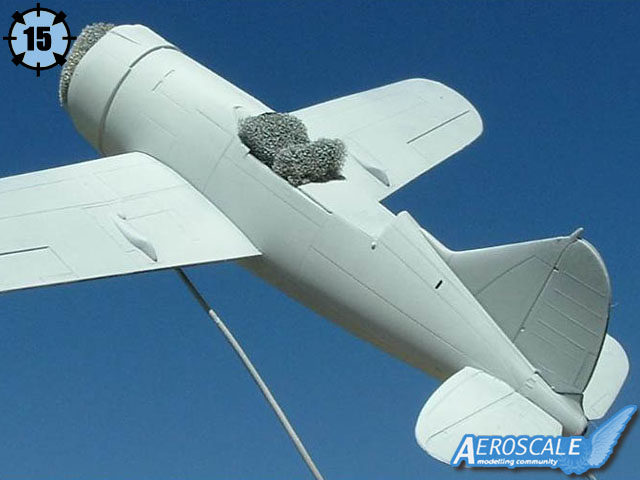
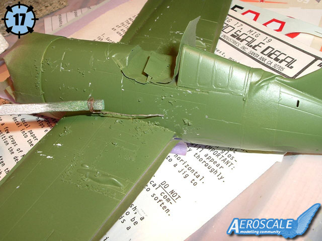
The fuselage halves and wing joints all needed much filler. But the shock and disappointment was the cowl ring of step 14. It was about 2-3mm wider than the fuselage cowl. I had to insert a styrene strip to spread the bottom fuselage to make it fit the cowl ring and then much filling and reshaping was needed. The superglue filler is the dark line along seams (pictures 13 and 14). There is a step between fuselage halves on the belly. Parts A8, nose gun bulges, do not mate well to the cowl nor to the muzzle openings. Parts D36 and D37, rollover bar halves, sit too high for the canopy. These parts should also mate to the top of the triangular pilots head armor atop the seat. Dry-fit and check alignments or the seat will be askew! The stabilizers have tabs for slots in the fuselage, but the slots needed reaming out and the tabs are far too small (pictures 15).
Ditto for mounting main wheels to their landing gear axles in steps 17 & 18. Find a reference for fitting the brake line, the illustration is unclear. While these lines are provided as P/E, clipping them off the fret left several minute burrs. Fashioning them of wire might be a better choice. The gear is mounted in step 19. The butt of the gear strut has a subtle pin that is to mount on a footer with a shallow hole molded in the gear well. Like the stabilizer-fuselage fit, these are too faint to be useful. The gear retraction rods connect to the retraction mechanism go inside the fuselage wheel wells, the retraction rods butting up against each other. It took a great deal of fiddle time to get these four ends of the gear to mesh up symmetrically. This step also is time to mount the solid exhaust stacks. I drilled mine out and then mounted them, it looks convincing but you might like to further drill through the cowling. These stacks look odd compared to photos of B.239s, which seem to have the stacks mounted higher and protruding from a notch in the cowl.
Step 20 is mounting the resin Revi gunsight (E4), canopy, prop and spinner, wing gun barrels, antenna mast, pitot tube and navigation lights. The clear parts are injected and look good. If you mount the Revi where it should be then the windscreen (F4) does not fit. If you did not shave the rollover bar top of (D36 and D37), the rear birdcage (F3) will not seat to the fuselage. Dry-fit and check alignments, because my canopy (F5) will not match up to the front or rear parts, and only sets halfway upon the canopy rails. Antenna mast (D42) is so scale-thin that all my TLC did not prevent it from breaking into three pieces! There is a faint outline scribed into the fuselage as its mounting guide, I really hope you already opened it up! The pitot tube is very thick, but the navigation lights are beautiful little pieces and fit like a glove. They protrude from the wingtips slightly outward, I do not know if this is accurate. There is even the relief tube vent on the lower fuselage under the port wing!
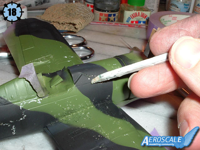
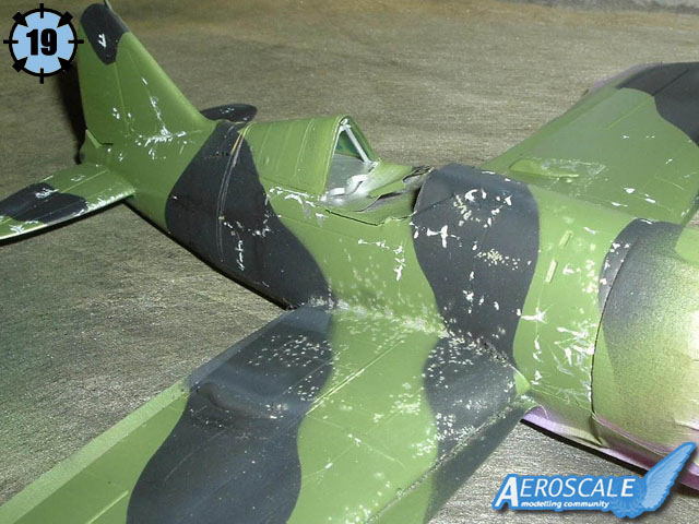
Painting
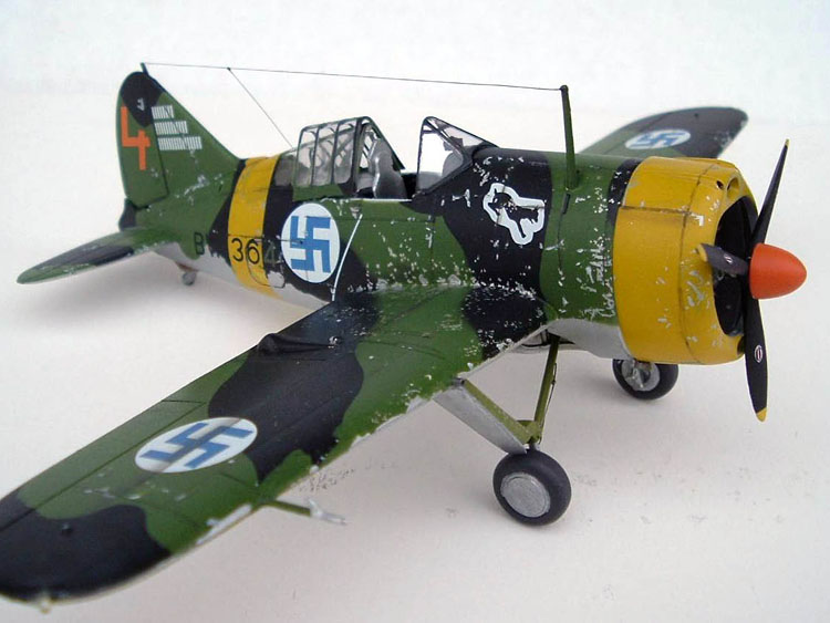
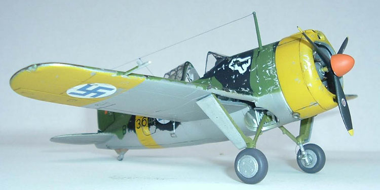
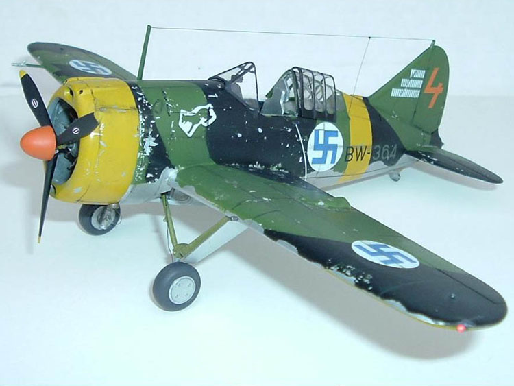
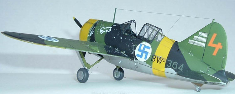
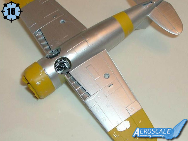
Throughout the instructions are notes about the colors to use, inside and out. F.S. numbers are used. Please refer to my article Salt Weathering for more informations about the painting process for this model (pictures 16 to 19).
Decals
These were the highlight of my build! Decals for nine different aircraft allow you to choose from as-delivered Brewsters in overall aluminum lacquer, olive and black camouflaged fighters of 1941-44, and even post-war markings (picture 20). They lifted free from the paper in seconds, never curled nor tore (I even dipped them directly into my setting solutions!), and conformed to every nook and cranny! Numbers are provided that you may build any serial number. I was befuddled at first with the serial number being in different colors until I realized they were painted olive over the black camouflage, and black over the olive! Classic Airframes R&D department even produced the fascinating victory markings used by Finnish ace Eino Luukkanen--beer bottle emblems!
Conclusion
This was my first complete limited-run model. While this model reminds me why I preferTamiyaGawa-engineered models, if you can build the average model of the 1970's and 80's, you can build it. Fitting was troublesome with almost every step. Superglue and filler is a must. Except for the engine sinkhole, molding is beautiful with minimal mold lines. Detail is exceptional. Potential for super-detailing the area housing the fuselage guns, engine accessories and gear retraction wells are beautiful. The decals and marking guide are great.
This built into a great looking model of the spunky Buffalo with which Finland gored swaths through the swarms of Stalin's hordes.


About the Author

FROM: TENNESSEE, UNITED STATES
I'm a professional pilot with a degree in art. My first model was an AMT semi dump truck. Then Monogram's Lunar Lander right after the lunar landing. Next, Revell's 1/32 Bf-109G...cried havoc and released the dogs of modeling! My interests--if built before 1900, or after 1955, then I proba...
Comments

Nice one Fred!
I'll definitely read your detailed construction notes when I tackle this little beast myself! It might have been your first short-run kit, but the result is a beauty!
Jean-Luc - Great job (as ever!) editing the photos.
All the best
Rowan
JAN 19, 2007 - 09:32 PM

Indeed! I deluged him with a plethora of pictures and he melding them together wonderfully!
I invite all of you who have built this kit to add your comments concerning your builds, if you experienced the same troubles that I did. Together, we can advise future modelers of this kit as to whether my problems were due to the kit, or due to me!
BTW, some extra photos can be seen on this page of the FUMS-Build forum:
https://aeroscale.kitmaker.net/forums/80786&page=6
JAN 20, 2007 - 03:29 AM


Another great addition to Aeroscale. This will come in handy when I break my kit off the shelf. Thanks
JAN 20, 2007 - 04:27 PM

Hi Fred!
talking about FUMS, do you have a list of the completed entries for that Campaign? I would like to make a Portfolio dedicated to the Finnish War. Maybe you or Eetu could write a nice historical background to go with the pictures?
Jean-Luc
JAN 20, 2007 - 04:37 PM

Having "attempted" to build this kit, it would have been a much easier process if I'd had Freds review before hand.
As for the review, everything is spot on in my opinion. I ended up building the Tamiya Buffalo because of time constraints on the FUMS campaign and supplementing parts of the CA kit such as engine cowling, rear fuselage tail assembly, etc. My two main complaints with the CA Buffalo kit are:
1. The plastic is beautiful but seems very "soft" or almost "rubbery". Experience building Tamiya, Academy, and Hasegawa kits has left me with a sense of just how much to cut, how hard to sand, and how much the plastic will "bend". The CA Buffalo kit is totally different to me. I found that when triming parts I often took off a bit too much because my hobby knife wanted to "dig" into the plastic more than usual. Is it just me or has anyone else ever experienced thie?
2. The directions leave the builder guessing at many stages. Drawings are often incomplete and it seems in a few steps the directions leave out crutial information on how to correctly install parts.
That said, I would not hesitate to build another CA Buffalo kit in the future. Now that I have a good review to guid me ( FRED ) I am not as intimidated by the process. Overall the kit is well done and given time and patience it will produce a beautiful result. As for CA kits in general, well I am ready to start another CA kit this week, the F5A Freedom Fighter in 1/48 scale.
JAN 21, 2007 - 01:15 AM

Hi gang
i still have not read Freds article ... he knows why. But as he asked me, here is my experience:
First let me state that this is one of the better CA kits ... one of the most overrated manufacturers IMO (if I see for what other manufacturers get bashed and smashed .... but I digress)
The kit is in the typical Special Hobby - CA Quality and looks good in the box (the kits done by Sword have a much harder and shinier plastic e.g. the F-5 or Bf 109 A). The wing(s) go together well and even the resin parts fit quite well. I added the Griffon ailerons but left out the landing flaps.
I built the cockpit-engine assembly into the right fuselage half (and arranged myself some tricky assembly for the rh side cockpit wall, which I should have mounted first). Then I glued the wing to the rh fuselage and made some adjustments to make it fit (the left fuselage side was also dryfit in this stage) Then I painted the interior and mountet the rest of the cockpit stuff.
 Closing the fuselage was a bit tricky and I had to sand the engine bulkhead and the rear bulkhead several times to make all fit to a bearable degree. Still the whole assembly needed some pressure to minimize further filling and sanding. I matched all lines but kept a 1mm gap where the left wing meets the fuselage. I am sure this was because I was a bit sloppy when glueing the right fuselage. I used "Pattex Stabilit Express" a fast curing 2k Epoxi to glue everything together.
 Now I removed the fin and replaced it with the Griffon parts. Then I added the tail end of the kit and the elevators from the Griffon set. Now some filling and sanding was required, but it was not very extensive as I did a good job aligning everything (though I had to reglue the u/c legs as they were off). I added some cockpit parts and attached the canopy (I was in a hurry as i wanted to get the thing done ... so I bet there are some smears and dust inside.
I masked the canopy with Bare Metal foil and the whole thing was primed with Citadel Black primer (first class product BTW). then I sprayed half a bottle Alclad alu on and sealed it with clear .... that is where I am now, but I do not expect many problems to come.
pix when it is done
best wishes
Steffen
Now I removed the fin and replaced it with the Griffon parts. Then I added the tail end of the kit and the elevators from the Griffon set. Now some filling and sanding was required, but it was not very extensive as I did a good job aligning everything (though I had to reglue the u/c legs as they were off). I added some cockpit parts and attached the canopy (I was in a hurry as i wanted to get the thing done ... so I bet there are some smears and dust inside.
I masked the canopy with Bare Metal foil and the whole thing was primed with Citadel Black primer (first class product BTW). then I sprayed half a bottle Alclad alu on and sealed it with clear .... that is where I am now, but I do not expect many problems to come.
pix when it is done
best wishes
Steffen
Closing the fuselage was a bit tricky and I had to sand the engine bulkhead and the rear bulkhead several times to make all fit to a bearable degree. Still the whole assembly needed some pressure to minimize further filling and sanding. I matched all lines but kept a 1mm gap where the left wing meets the fuselage. I am sure this was because I was a bit sloppy when glueing the right fuselage. I used "Pattex Stabilit Express" a fast curing 2k Epoxi to glue everything together.
Now I removed the fin and replaced it with the Griffon parts. Then I added the tail end of the kit and the elevators from the Griffon set. Now some filling and sanding was required, but it was not very extensive as I did a good job aligning everything (though I had to reglue the u/c legs as they were off). I added some cockpit parts and attached the canopy (I was in a hurry as i wanted to get the thing done ... so I bet there are some smears and dust inside.
I masked the canopy with Bare Metal foil and the whole thing was primed with Citadel Black primer (first class product BTW). then I sprayed half a bottle Alclad alu on and sealed it with clear .... that is where I am now, but I do not expect many problems to come.
pix when it is done
best wishes
Steffen
JAN 21, 2007 - 04:14 AM
 cheers
Steffen
cheers
Steffen
Great article Fred,
My experience building the CA Buffalo mirror yours, if there is one piece of advice which Classic Airframes gives over and over and over is to dry fit the assemblies prior to gluing... this is for obvious reasons. Overall, a good little kit.
Frank
JAN 24, 2007 - 09:49 AM
Copyright ©2021 by Fred Rick Boucher. Images also by copyright holder unless otherwise noted. The views and opinions expressed herein are solely the views and opinions of the authors and/or contributors to this Web site and do not necessarily represent the views and/or opinions of AeroScale, KitMaker Network, or Silver Star Enterrpises. Images also by copyright holder unless otherwise noted. Opinions expressed are those of the author(s) and not necessarily those of AeroScale. All rights reserved. Originally published on: 2007-01-20 00:00:00. Unique Reads: 22931

WEB HOSTING BY


Copyright ©2021 AeroScale and Kitmaker Network, a subsidiary of Silver Star Enterprises
All Rights Reserved. Please read our Conditions of Use and Privacy Policy.
All Rights Reserved. Please read our Conditions of Use and Privacy Policy.