

1⁄35Focke-Wulf Fw 190 D-9 - Part 3
...
Post a Comment
AH WOODY, HAND ME THAT PAPER PATTERN, EH?
See Photo 3-G. Hokay, yep. . . we read from left to right, but I forgot. So letter "a" is on the far right. Now I'll discuss the additions to the engine compartment to enhance the RevellUSA kit engine, hopefully to look more like the real thing, along with several other points I'll mention. But keep in mind what I said above about how each piece needed to be portable, removable, so I could connected the parts together in the engine compartment and then be able to remove them individually, once again.I have previously mentioned about using basswood and wooden dowel rods of various diameter thicknesses to fabricate pieces for this model. From email with my friends in the UK and Europe, I've gotten the impression that basswood is not readibly available in all parts of Europe. In the USA, basswood is a relatively inexpensive hobby material like balsa wood only much better to work with, than the too soft and unstable balsa wood. Basswood is stronger, like carving a piece of inexpensive pine. And basswood is easy to carve, sand and paint. Dr. Frank Spahr, DDS., my good friend in Deutschland says that boxwood is readily available in Europe. And boxwood is one of the best kinds of wood for hobbiests. It's is considered a premium high quality wood here in the USA and is somewhat expensive. But hopefully, it is available in Europe and not as expensive as here in the USA. If you can't find basswood, then boxwood is even better.
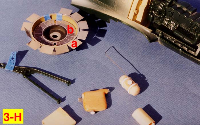
We're still at Photo 3-G: Letter "a" and letter "d" are just pieces of manila card stock; paper that has a little heft, a little more thickness to it than bond paper, or printer paper would have. These two paper shapes were cut and taped together to be patterns. I used these temporary shapes to check if they were near the correct size in scale to fit in their proper location on and around the kit engine, and still leave room for all the other elements that would go into the engine compartment. The Squadron Signal Walk Around book on the Dora was essential for this project. I could not have even attempted it without that valuable reference of a full scale restored FW 190 D-9. So if the paper pattern part seemed to fit correctly then I used that shape to help me with creating/carving the scratchbuilt part. Letter "b" shows the scratchbuilt coolant tank (yellow in color, on the real aircraft and on my model as well). Even though I'd made the paper pattern (letter "a"), I still had to make this part twice as the first one was too big in diameter and a fraction too long from front to back. The coolant tank was a sawed section of wooden dowel rod that had been sanded to the rounded contour on both ends. The white straps were pieces of very thin styrene plastic strips attached with super glue. The coolant tank opening/lid was made from a piece of gray styrene tubing. The top or lid of the tubing opening was covered with a square piece of white sheet styrene and glued to the tubing with Tenax 7R liquid glue. The next day when the bond was good and solid, I sanded off the edges of the sheet styrene "square" so that is conformed to the top of the gray tubing. Letter "c" is the oil tank that was carved from basswood using the paper pattern (letter "d") as a guide. The full scale "real" oil tank is somewhat unique in that the port side tubular section of the engine mount passes right through the oil tank. Perhaps you can see a small part of the gray plastic tubing sticking out the right side of that basswood oil tank. Letter "e" is the kit port side engine mount. I had to lengthen the area of both engine mounts where they connected into the fire wall so that the engine would be in the exact correct location for the forward engine cowl ring/flaps to be lined up properly. Letter "f" is the kit cowl ring from the old Hasegawa kit that I used. The silver colored PE engine cowl flaps are attached with blue low tack masking tape. (Remember? Dry fit, dry fit, dry fit, . . . zzzzzz) The PE cowl flaps are also from the old Hasegawa kit. Photo 3-H is another view of the same pieces. Letter "a" shows the old Hasegawa PE cowl flaps again, and letter "b" shows the old Hasegawa kit PE part, the insert which was a portion of the engine forward radiator screen, that would be positioned right behind the prop spinner. Photo 3-J shows a different view of the same old Hasegawa kit pieces.
RATA TAT TAT, . . . A RESIN PAIR
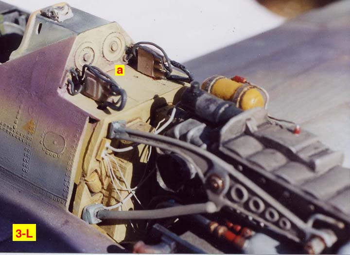
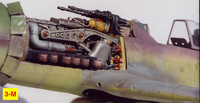
Photo 3-K shows the two fuselage MG 131 machine guns in resin that were part of the Verlinden detail set. Hopefully, you can see the color difference between the detail set's tan resin and the added white sheet styrene pieces that were glued onto the bottom of the resin machine guns. The added white styrene pieces were necessary. And for the same reason that was mentioned above. I return to that "theme" once again. The height and forward reach of those two gun barrels has to be just in the exact position so they would protrude from the opening in the top part of the engine cowling, the portion of the engine cowling that was stationary.As before, I would need to be able to dryfit it all together and then be able to take it all apart again to make adjustments. Plus, the white styrene pieces glued onto the machine guns, the portion that was hanging down, had to fit perfectly over the top of each machine gun's magazines located directly below in the resin firewall. I made those "descending" styrene pieces longer than necessary, and then sanded each one to the correct length after a lot of trial and error, while the dryfitting process continued.Major amounts of discipline were required here and a continual self reminder that "to get what you want, to achieve something of value in this life, you'll have to work your tail off to achieve it." I strived to keep in mind that nothing worthwhile comes easy. Hind sight is 20-20 . . . . revisited: If only I'd have put that basic truth in practice when I was 30 years of age. Yeh, yeh. "If, Ands, and buts, . . . were candies and nuts, what a sweet world this would be", right? Look at Photo 3-L and 3-M. At letter "a" in the 3-L photo you see the port and starboard electrical boxes that sat outside both machine guns. These boxes were also resin pieces from the Verlinden detail set. The dark gray wiring is solder wire, again. Perhaps if you look closely at photos 3-L and 3-K you will notice a variety of dark gray/light gray and metalic shades painted on the generator, (the generator is on top of the engine, to the immediate left of the yellow coolant tank in photo 3-L) engine oil tank, the engine mounts, and at different places on the engine block. Some of the details have a bluish cast to them; some have a small amount of white added to the bluish gray, or white added to the metalic engine oil tank to dull the sheen of that surface. I wanted to bring this different way of thinking and different way of painting aircraft model parts to your attention in an attempt to explain another aspect of how I conceive of model building that many other aircraft modeler builders would not agree with. They would definitely think my approach was wrong. (I'm referring to the painting of details, down in the interiors of a model, such as the wheel wells, the cockpit, inside the access panels, inside the wing machine gun bays, etc.)
SUNLIGHT: SHOULD THE ASPECT OF LIGHT AND SHADOW MATTER?
For one thing the color photos in the Squadron Signal book show the tonal differences in the engine compartment. And secondly, I feel a slight variation of tone with the colors, make the engine more interesting to look at. I feel this approach gives the engine compartment more eye appeal, and hopefully gives it more of a look and feel of realism. Also as I painted these details, I tried to keep in mind the point I made in Part II of this article: How the play of sunlight would have affected the highlights and shadows in the real aircraft: in this case, in the engine compartment. To state my opinion another way, WWII Luftwaffe regulations might have stated that a Dora's interior cockpit was painted RLM 02 Gray or perhaps RLM 77 Primer. Knowing this, some modelers paint the entire cockpit floor and side walls RLM Gray. So that would be historically accurate as to the color selection. But in my opinion when a person looks down into a model with RLM Gray painted into the cockpit, that same cockpit doesn't look as realistic as painting the cockpit with the awareness of sunlight creating highlights and shadows. But you understand this is just my opinion!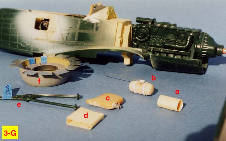


About the Author


FROM: KANSAS, UNITED STATES
I am primarily a figure painter and have been painting figures about 3 years now; still consider myself a novice. However, I started building models in 1965 and as a retired newspaper artist, I now have time to build models all the time, just for the fun of it and as a way to express my creative inn...
Comments
Copyright ©2021 by Rick Brownlee. Images also by copyright holder unless otherwise noted. The views and opinions expressed herein are solely the views and opinions of the authors and/or contributors to this Web site and do not necessarily represent the views and/or opinions of AeroScale, KitMaker Network, or Silver Star Enterrpises. Images also by copyright holder unless otherwise noted. Opinions expressed are those of the author(s) and not necessarily those of AeroScale. All rights reserved. Originally published on: 2007-01-20 00:00:00. Unique Reads: 9076

WEB HOSTING BY


Copyright ©2021 AeroScale and Kitmaker Network, a subsidiary of Silver Star Enterprises
All Rights Reserved. Please read our Conditions of Use and Privacy Policy.
All Rights Reserved. Please read our Conditions of Use and Privacy Policy.