

1⁄35MH-60G Pave Hawk
12
Comments
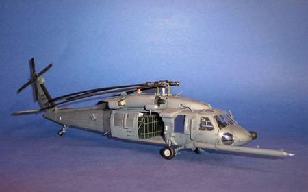
Here is the latest addition to my Helicopter collection, the MH-60G. This 1/48th Pave Hawk was made by Italeri, kit no.# 2612. I won’t go into the kit's detail as this is a build article. For a in box look, I have a review of this kit - MH-60G Pave Hawk. In addition to the kit, I also used Eduard's MH-60G Pave Hawk interior - item # 49 330. First I’d like to thank Merlin (Rowan Baylis) for sending the Eduard photo etch set to me and giving me the chance to review it.
This Pave Hawk is based on an earlier version of a Search and Rescue MH-60G. The newer MH/HH 60’s are being updated using the RWR, repositioned navigation lights, Plume detectors, Flir turrent mounted on center of nose, Chaff/Flare dispensers on sponsors and two each along the tail boom and the removal of the HF antenna.
Construction
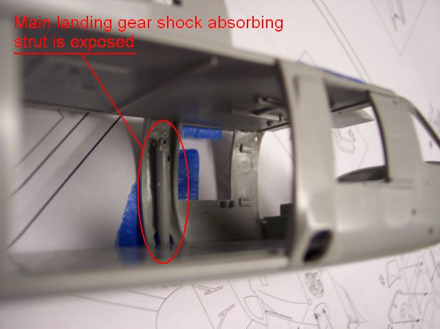
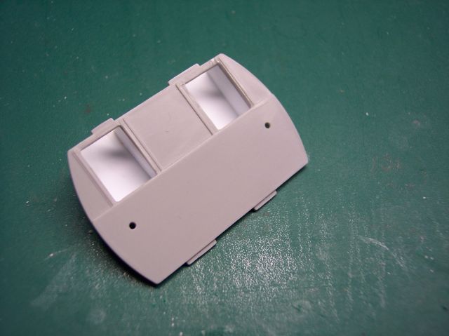
Before I start building my kits, I dry fit most parts to see what is missing and to find any of the fit problems. One of the things I did notice was that there was no side wall interior detail. Seeing this I noticed that the main shock absorbing strut is visible, (figure 1). Using a contour gauge, I was able to make a pattern for the new walls using 0.3mm Evergreen plastic sheet and 0.3 rod. If you plan on using the photo etch set, you're going to need to remove the mini gun and side armor mounts, (figure 2). Building the walls wasn’t as easy as I first thought, but with some patience they were worth the time, (figures 3 and 4). You will need to install the main landing gear, parts 19a and 20a at this point - you’ll never get them in once you build in the interior walls.The rear cargo wall, part 40b will need to be drilled out to glue in the internal fuel cell bladder. I also cut and boxed in the openings. Either way you really don’t see it (figure 5).
Moving on to the interior fuel cell bladder, you’ll have to file and sand off the molded on straps, (figure 6). The Eduard straps and come-alongs are very convincing, so don’t let this step scare you from doing it, it’s worth it. You’ll see the results further down.
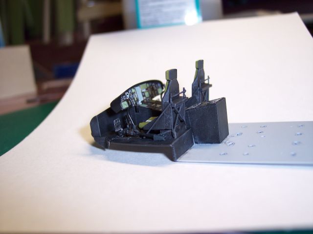
Moving on to the cockpit, figure 7), you’ll have to remove some of the molded in detail and replace with the photo etch detail. The instrument panels, parts 4, 5, 6 and 17 were not installed during this step due to the fact that they are pre-painted. Doing so will make it easier for you to paint the interior without masking the parts or even causing them damage. The pilots' seats were furthered detailed using 0.4 and 0.5mm rod.
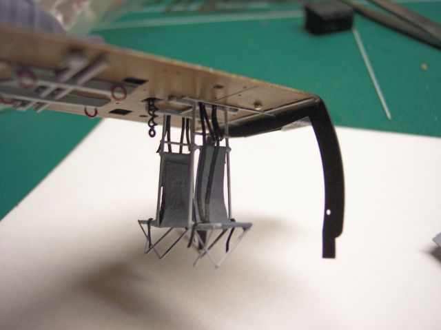
The kits cargo area lacks most of it’s interior detail, and without it looks pretty empty. So I decided to spruce it up by building the gunners' seats and the fast rope supports brackets. The gunners' seats, (figure 8) were made from 0.4 rod and the legs are 0.3 rod. The cable supports were made from stretched sprue. The seats' harnesses were made from masking tape and foil. I also scribed in the sound proofing along the cargo ceiling to further detail the ceiling some, (figure 8a).
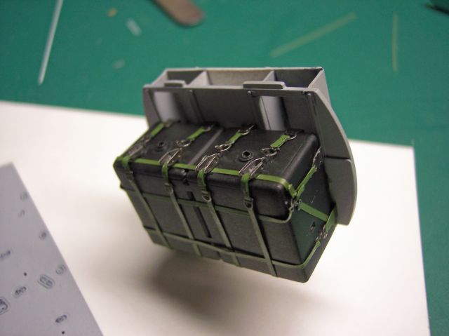
Going back to the fuel cell bladder, I painted it with Model Masters Aircraft Interior Black, and the straps were painted with Model Masters Medium Green. Once everything dried, they were installed following the steps in the instruction sheet, (figure 9).
Returning to the cockpit, it was painted with Model Masters Flat Black, dry brushed with Tamiya’s NATO black. The cargo bay walls, seats and floor were painted with Model Master Dark Ghost Gray. Once the paints dried I installed the remaining instrument panels, parts 4, 5, 6, and 17.
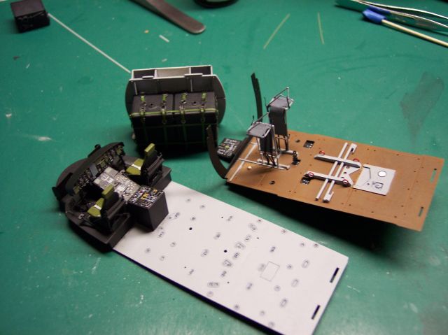
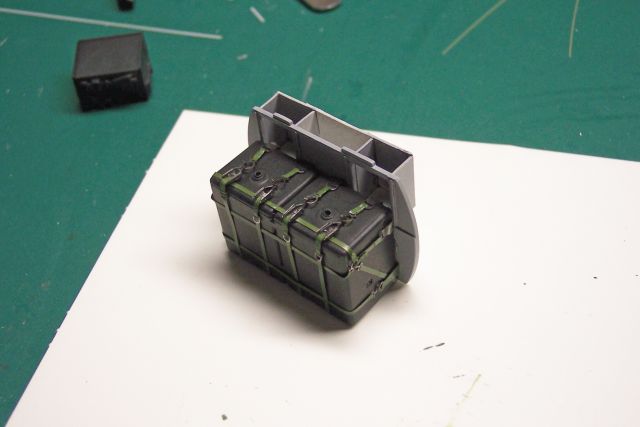
The cargo ceiling was painted with Polly Scales Rust lightened with Flat White. The gunners' seat and fast rope support brackets were glued on (figure 11), and the fuel cell bladder was installed on to the rear cargo wall (figure 12) In (figure 13) it shows all of the interior painted. At this stage I still needed to add more detail in the cargo area).
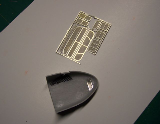
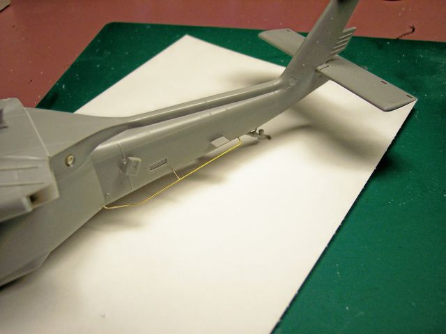
In (figure 14) I cut out the molded in screens in the hydraulics bay cover and replace it with a plastic screen mesh and a piece of photo etch from the spare parts box. The photo etch grills are for NASCAR bumper ducts, and can be used for many applications. You can get from Slixx.com at the coat around $11.00 dollars. The HF ‘’Towel Rack’’ antenna was made from 0.5 brass rod, and the APU exhaust was drilled out and a drilled out rod was added in place, (figure 15).
Step 3 of the kits instructions has you installing the cockpit/cargo interior into the fuselage halves. During this step I did not install the tail rotor, part no.# 34b. I did however install the tail rotor retaining ring, part no.# 14b. I also did the same for the main rotor assembly, only installing part no.# 17b and 15b.
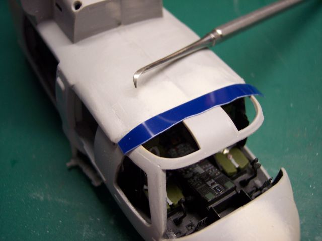
Steps 4 & 5 involve installing the glass, another procedure I usually do last. I also left of the re-fueling probe, parts no.# 33a, 34a, and 35a. I will install the re-fueling probe just before I start to paint. This will make it easier to handle and paint during the rest of the construction.
Once the two fuselage halves were joined together, I noticed that it needed some putty along the roof line, nose bay and at the bottom of the fuselage. After the putty cured and sanded, it needed to be re-scribed. This was achieved using Dymo Tape and a Scribing tool, (figure 16).
In steps 7 & 8 you’ll have to pay close attention to the assembly for the parts of HIRSS, part numbers 49, 50, 51, 52, 53, 54, 55 and 56.
Now that I’m finished with the main assembly I’ll go back and install the parts that were skipped over with the exception of the glass and both rotor assemblies.


About the Author


Comments

on the HH 60 the model shows the center consoul extends into the cabin area
is that the way its supose to be
i know on the UH-60 L it stops even with the storage boxes ont the back of the pilots seat
MAY 14, 2006 - 09:29 PM
Yes, that is where the controls for the extra radios, chaff/flare launchers, and some other mission/type specific equipment for the MH/HH models are housed. You can see the extended console below.
 Here is an HH-60G full walk-around as well.
Here is an HH-60G full walk-around as well.MAY 14, 2006 - 09:36 PM

Joe, congrats man on the fine build and excellent well written article. Almost makes me want to give choppers a try! cheers Kevin
MAY 15, 2006 - 12:26 AM

Gee.... Joe, that's a very nice article.....
Thanks for writing it.
MAY 15, 2006 - 04:27 AM

Hi Joe!
Great feature and awesome model! The interior detail is as always top class!
Jean-Luc
MAY 15, 2006 - 10:09 AM

great build and all, but, just so you know, the pitot tubes are on backwards.
JUN 30, 2006 - 12:34 AM

Nice build Joe but the only thing that bothers me , is that you would hardly ever see a USAF 60 with the blades folded. The blades have to be
manually folded. The reason I know I'm a ex H-3 / H-53 / MH-60G crew
chief. In fact retired.
JUL 14, 2006 - 05:49 AM

Thanks all for the complements, it was a great little kit to build. I have plans on doing a few more now that Mike Grant has a new decal sheet out on the 60B series.
Paul thanks
not sure why that happened, must have been one of those late night oversights. Hey we all make mistakes and over look something from time to time. I was able to remove them with out damage and place them in the right direction.
Hey Don,
Thanks
.here is a sentence out of a MH-60G Pave Hawk book, Im sure with out doubt they are, in fact most of the pics Ive seen were just as you said. See I was inspired by (2) photos of a Pave Hawk rolling out of a C-5 Galaxy, but mostly I like to folds back the blades on the Helicopters to save space on the shelves. Im also working on a 1/35 Pave Hawk which is about 20% started, I plan to fold her up as well.
JUL 14, 2006 - 09:41 AM
Copyright ©2021 by Joe Szczygielski. Images also by copyright holder unless otherwise noted. The views and opinions expressed herein are solely the views and opinions of the authors and/or contributors to this Web site and do not necessarily represent the views and/or opinions of AeroScale, KitMaker Network, or Silver Star Enterrpises. Images also by copyright holder unless otherwise noted. Opinions expressed are those of the author(s) and not necessarily those of AeroScale. All rights reserved. Originally published on: 2006-05-15 00:00:00. Unique Reads: 23837

WEB HOSTING BY


Copyright ©2021 AeroScale and Kitmaker Network, a subsidiary of Silver Star Enterprises
All Rights Reserved. Please read our Conditions of Use and Privacy Policy.
All Rights Reserved. Please read our Conditions of Use and Privacy Policy.