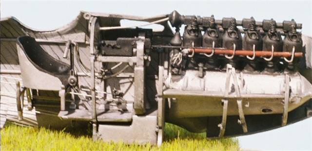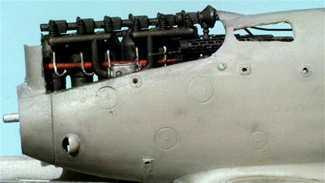
I added an oil tank from a cylindrical section for sprue with a sprue slice as a cap. This is located on the pilot's right side of the engine compartment back on the rear portion of the engine bearer shelf.
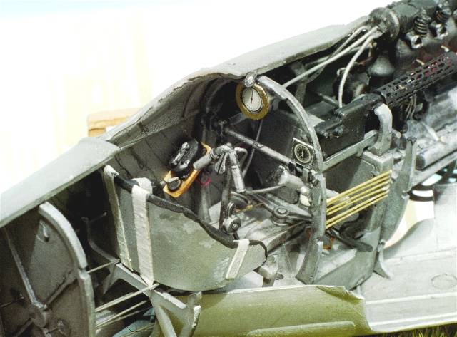
Here is a list of "other items that I added to the cockpit.
1. tachometer gauge face and bezel.
2. main fuel tank gauge face.
3. air pump gauge. / "Manometer."
4. 2 lap and 2 shoulder harness / webings and 4 PE buckles.
5. floor mounted compass gauge face and bezel.
6. 2 foot stirrups to the rudder bar.
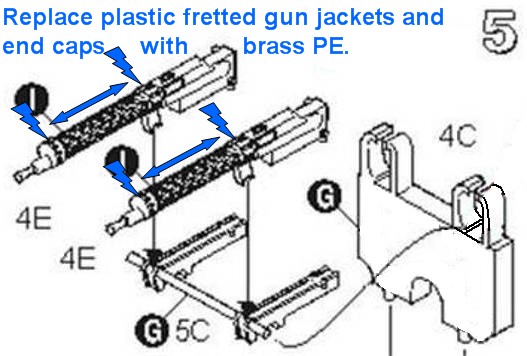
7. Synchronizer cables from engine to gun breaches.
8. 2 Bowden cables from control coloumn to the guns.
9. 2 rudder , 4 elevator cables.
10. brass conduit pipes for the electrical wiring from the instrument cluster on the pilot's right.
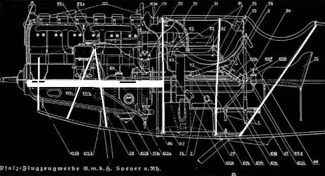
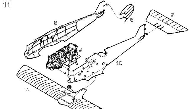
Step 11.) Now glue the fuselage halves (1 & 2 C ) together and allow to dry. To get the fuselage to close up you will have to clip off the decompression handle on the upper rear tower of the engine. This was removable anyway on the real machine ( it unscrewed.)
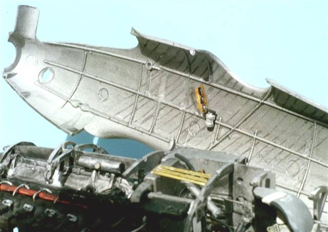
Then erase all union seams. Add the rudder and horizontal tail unit assemblies. Careful sanding helps the horizontal tail unit ( 3 C ) fit properly. I used gap filling super glue (semi gelatin) to fill joint seams between all plastic parts joined to the fuselage. Note that canting control surfaces tends to give the piece a more natural look seen in period images of the real aircraft. The kit rigging control horns ( 9 G & 2 E X 2 ) can be used per the instructions. Add the lower wing ( 1 A ) at this time.
Concerning the lower wing ( 1 A ) attachment. I had to trim about 1/16 of an inch from the trailing end and had only minor sanding to finish. The fit is near perfect. BUT you may remember I had to cut down the fuel spout (5 Z ) and the engine carburetors ( 6 G ). Had I left these items alone I would have run into some serious fit problems with the lower wing and fuselage at this point. Images to be posted .