

Early Aviation
Discuss World War I and the early years of aviation thru 1934.
Discuss World War I and the early years of aviation thru 1934.
Hosted by Jim Starkweather
1/32 Roden Pfalz D.III the build.
redalb2253

Joined: June 02, 2006
KitMaker: 235 posts
AeroScale: 60 posts

Posted: Wednesday, September 05, 2007 - 08:37 AM UTC
I know what you mean about the Battleaxe DVII I have that lump of plastic myself I put it up and probably will mess with it later, The DVIII isn't as bad as the DVII just a few pieces to rebuild on that kit.
JackFlash
Joined: January 25, 2004
KitMaker: 11,669 posts
AeroScale: 11,011 posts
Posted: Wednesday, September 05, 2007 - 12:27 PM UTC
Quoted Text
The information provided on this build is fantastic. Keep the pictures coming.
As you requested. The following are images taken after the addition of gauge faces, bezels, simulated conduit, temporary placement of fretted gun jackets, more plumbing, lap and shoulder harness' and buckles.


JackFlash
Joined: January 25, 2004
KitMaker: 11,669 posts
AeroScale: 11,011 posts
Posted: Wednesday, September 05, 2007 - 12:34 PM UTC
JackFlash
Joined: January 25, 2004
KitMaker: 11,669 posts
AeroScale: 11,011 posts
Posted: Wednesday, September 05, 2007 - 12:38 PM UTC
Lap and shoulder harness webings are from masking tape the buckles are Tom's Modelworks brass.


Rittersbach
Joined: August 16, 2007
KitMaker: 83 posts
AeroScale: 80 posts
Posted: Wednesday, September 05, 2007 - 01:27 PM UTC
Lovely detail Stephen, where oh where would you be without your optivisor.

JackFlash
Joined: January 25, 2004
KitMaker: 11,669 posts
AeroScale: 11,011 posts
Posted: Wednesday, September 05, 2007 - 03:32 PM UTC
Probably doing 1/1 scale only. 

Kitboy

Joined: July 20, 2006
KitMaker: 258 posts
AeroScale: 256 posts

Posted: Wednesday, September 05, 2007 - 09:55 PM UTC
I just keep starring at these pictures and think about the effort put into the build.
Greetings, Nico
Greetings, Nico
JackFlash
Joined: January 25, 2004
KitMaker: 11,669 posts
AeroScale: 11,011 posts
Posted: Wednesday, September 05, 2007 - 10:02 PM UTC
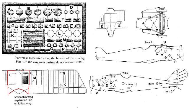
Note the top wing as we are moving that way. The original aircraft had a three piece top wing. the center section housed the radiator and the gravity tank. To represent this you will have to scribe the lines between these areas on both upper and lower surfaces. On the Tom's Modelworks direction he notes this but I have added a red border to the center section area.
Also you will want to sribe a box outline to represent the underside of top wing to represent the gravity tank in this same area.
Also you will want to sribe a box outline to represent the underside of top wing to represent the gravity tank in this same area.
JackFlash
Joined: January 25, 2004
KitMaker: 11,669 posts
AeroScale: 11,011 posts
Posted: Sunday, September 09, 2007 - 01:25 PM UTC
Quoted Text
I just keep starring at these pictures and think about the effort put into the build. Greetings, Nico
Thanks Nico, coming from you that is a fine compliment. The overall silbergraü was a bit hard for me to accept. Even though it was historically correct, I was afraid in a smaller scale than the original it would look too plain and possibly lose definition for the overall work details.

But it turned out excellent for the details if I kept them in basic colours of black, white brass,rubber, wood and leather. I think that the silbergraü interior painting sets off these colours to good advantage.

The work is easier for me because I have that parts yard for WWI kits and an army of "Tinker Gnomes" in my basement.

Then there is my twin. . .

JackFlash
Joined: January 25, 2004
KitMaker: 11,669 posts
AeroScale: 11,011 posts
Posted: Sunday, September 09, 2007 - 01:45 PM UTC
Remembering that the top wing came in three pieces on the original, we must now deal with the minor leading edge issue. The leading edge of the top ( 2 A) wing from about the radiator over to the pilot's right side of the top wing has a minor flaw. Possibly because of the single wing molding method. Plunging it into warm water and gently bending the edge into place fixes it completely. I have had to do this even on 1/48 scale kits so its not a big deal.
Step 12.) Top wing ( 2 A) details show the aileron control actuators ( 6 E ) and the radiator filler tower (13 G ). In most cases a shutter system was employed on the D.III and D.IIIa airframes. This was to either dissipate or retain heat in the radiator. Depending on the weather conditions during a given patrol or flight. I decided to erase the molded in detail except for the rails the shutter is attached toand use the Tom's brass. In truth you only gain a bit of depth but I like it.

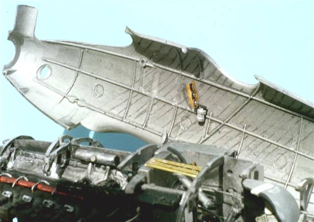
Step 13.) Brings the fuselage and wings together. It should be noted that most circular engine access panels need to be flush to the surface but not completely erased. For the top wing( (2 A ) I generally paint the undersurface of the top wing and the upper surface of the lower wing (1 A ) at this point before assembly and rigging. It depends on what you are comfortable with. I chose also to pin the wings and struts together. This is done by drilling corresponding holes then insert and glue brass pins in the hole sockets to unify wings and struts. Note if the cabane ( 9 E X 2 ) or wing struts ( 1 E X 2 ) ends enter the wing at an angle drill your insert holes accordingly.
Step 12.) Top wing ( 2 A) details show the aileron control actuators ( 6 E ) and the radiator filler tower (13 G ). In most cases a shutter system was employed on the D.III and D.IIIa airframes. This was to either dissipate or retain heat in the radiator. Depending on the weather conditions during a given patrol or flight. I decided to erase the molded in detail except for the rails the shutter is attached toand use the Tom's brass. In truth you only gain a bit of depth but I like it.
Step 13.) Brings the fuselage and wings together. It should be noted that most circular engine access panels need to be flush to the surface but not completely erased. For the top wing( (2 A ) I generally paint the undersurface of the top wing and the upper surface of the lower wing (1 A ) at this point before assembly and rigging. It depends on what you are comfortable with. I chose also to pin the wings and struts together. This is done by drilling corresponding holes then insert and glue brass pins in the hole sockets to unify wings and struts. Note if the cabane ( 9 E X 2 ) or wing struts ( 1 E X 2 ) ends enter the wing at an angle drill your insert holes accordingly.
JackFlash
Joined: January 25, 2004
KitMaker: 11,669 posts
AeroScale: 11,011 posts
Posted: Sunday, September 09, 2007 - 08:06 PM UTC

JackFlash
Joined: January 25, 2004
KitMaker: 11,669 posts
AeroScale: 11,011 posts
Posted: Sunday, September 09, 2007 - 08:11 PM UTC
The top wing went on without a hitch. Will shoot images tomorrow.
JackFlash
Joined: January 25, 2004
KitMaker: 11,669 posts
AeroScale: 11,011 posts
Posted: Tuesday, September 11, 2007 - 11:26 PM UTC
Ok the good news is that the build is almost complete. Decals and a touch up are scheduled for the next couple of days. But first more images to fill up the roll of film and they will be going out for processing later today.
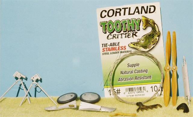
My only substitution for the kit parts were my landing gear legs are made from extruded brass ( oval crossection) . No matter what kit, I just don't trust plastic undercarriages.
The rigging in 1/32 scale, is done using some unique 10 lbs. fishing line. Essentially it is twisted wire sheathed in thin plastic. For fish that like to chew or saw through the line. More on that later. The control cables and landing gear rigging are done in a smaller fine wire.
JackFlash
Joined: January 25, 2004
KitMaker: 11,669 posts
AeroScale: 11,011 posts
Posted: Wednesday, September 12, 2007 - 01:22 PM UTC
Here is the beginning of the rigging.
JackFlash
Joined: January 25, 2004
KitMaker: 11,669 posts
AeroScale: 11,011 posts
Posted: Wednesday, September 12, 2007 - 01:30 PM UTC
Here are some of the parts that needed to be installed two days ago. Note the fishing line I mentioned earlier.
JackFlash
Joined: January 25, 2004
KitMaker: 11,669 posts
AeroScale: 11,011 posts
Posted: Wednesday, September 12, 2007 - 01:39 PM UTC
Now the build is almost completed. Next the decals, the aileron actuation balances and a final touch up.
JackFlash
Joined: January 25, 2004
KitMaker: 11,669 posts
AeroScale: 11,011 posts
Posted: Wednesday, September 12, 2007 - 01:48 PM UTC
The unfiltered light tends to wash out some of the details. But there is not any weathering or texturing applied yet to the areas that will need shadows.


SuccorPhysh
Joined: June 24, 2007
KitMaker: 82 posts
AeroScale: 81 posts
Posted: Wednesday, September 12, 2007 - 03:15 PM UTC
Outstanding work.
JackFlash
Joined: January 25, 2004
KitMaker: 11,669 posts
AeroScale: 11,011 posts
Posted: Thursday, September 13, 2007 - 04:43 AM UTC
Quoted Text
Outstanding work.
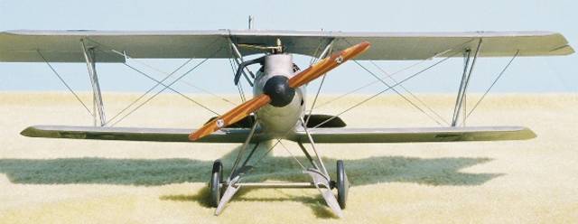
Thank you sir. I also had a request for a more detailed shot of the painted kit propeller.
JackFlash
Joined: January 25, 2004
KitMaker: 11,669 posts
AeroScale: 11,011 posts
Posted: Saturday, September 15, 2007 - 03:06 PM UTC
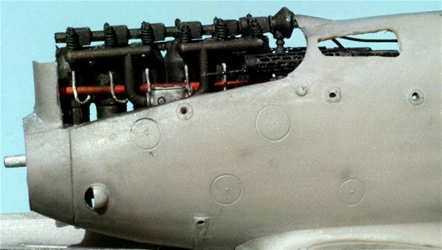
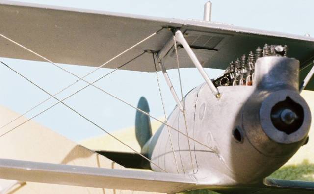
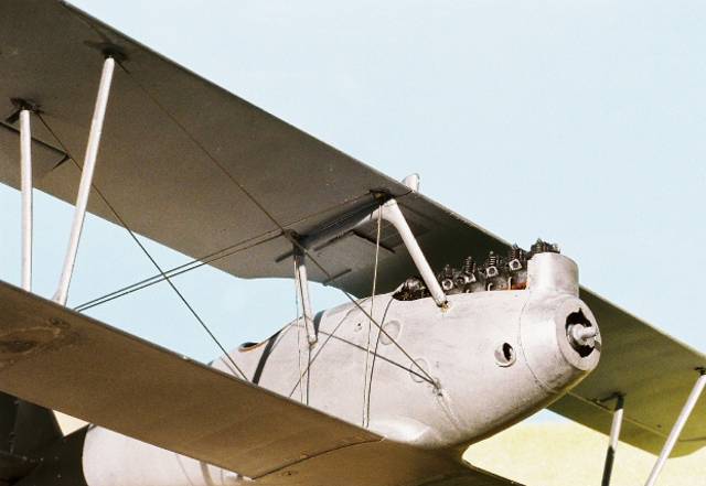
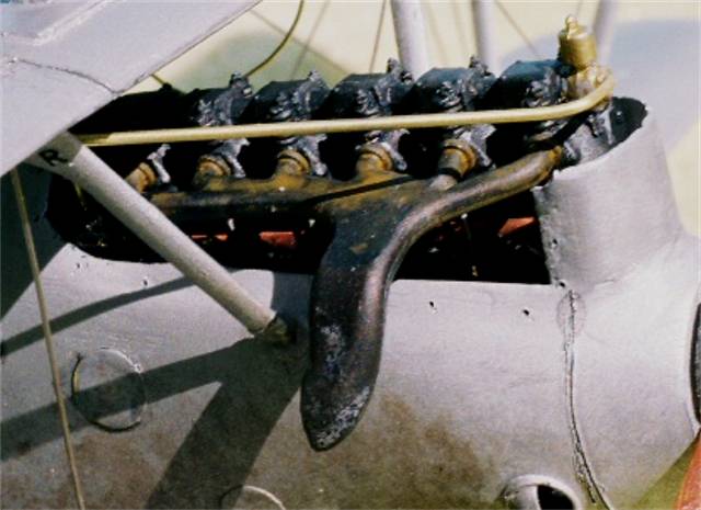
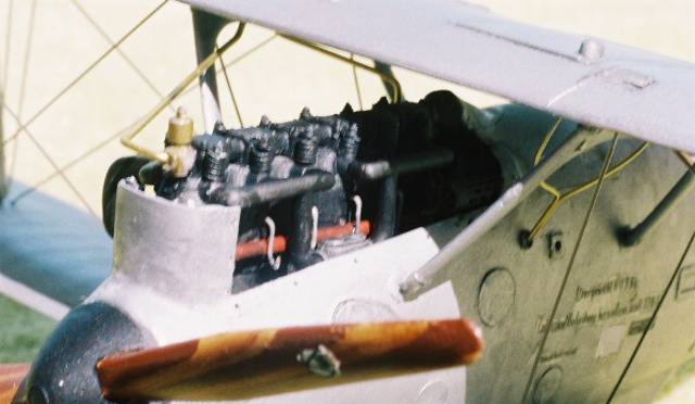
Step 14.) Assembles with water / coolant plumbing (12, 16 & 19 G ) and engine exhaust manifold (4 G ). The common exhaust is seen here but there were several manufacturers. There was even an early version where the exhaust horn was ahead of the #1 cylinder.
Step 15.) Is the installation of the fuel lines( 8 G ) for the reserve / gravity tank.
Step 16 .) The weakest part of a Vee strut landing gear assembly in plastic is the side to side twist. In many kits this usually causes the plastic gear legs to eventually dislocate or break. But with the Roden kit I use the kit landing gear legs (18, 26 G ) and the exposed axle ends (16 F ) with the appropriate diameter blackened brass rod. I use upholstery thread to wrap around the lower legs of the landing gear with the axle, to simulate the bungee shock chords. This looks like the original and actually secures the axle in place with one drop of cyanoacrylate glue. Finish any rigging now.
Step 17.) Add the tail skid ( 3 F ) . I personally like scratch- building my kit propellers from light and dark woods. I have also learned to paint the laminations with convincing effect. Most f the Pfalz fighters were equipped with the light and dark laminated propellers. Carefully check the aircraft profile your modeling to choose the right propeller. Roden offers two possibilities with this kit. The company determined the paddle profile of the propeller (it was their trade mark) while the engine application determined its pitch and length. So about five profiles could be seen on the D.III, but with the same pitch because of the factorys installation of the Mercedes D IIIa 170hp motor. Now I modify and add the tail skid ( 3 F ) After the final clear coat of your model dries thoroughly attach your windscreen with white glue.
JackFlash
Joined: January 25, 2004
KitMaker: 11,669 posts
AeroScale: 11,011 posts
Posted: Saturday, September 15, 2007 - 03:25 PM UTC
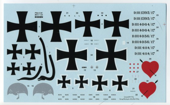
Kit decals: These decals are very easy to work with and seem very resilient. With care repositioning or adjustments are not a problem. I did use Sol & set solutions and cut very close to the colored areas. If you do so, care must be taken at this point to use a SHARP razor knife blade. ( Xacto #11). I like my decals to look like they are painted on. And the removal of the clear border aids in that.
For the average modeler without sol or set you may want to use a little diluted white (poly) school glue (50% water -50% glue), for better decal adhesion. Before applying water to the decals you may find that cutting the smallest bits (even with a sharp knife) actually lifts the decal from the paper. Yet, they do seem to stick well with either the sol & set or the diluted glue.
JackFlash
Joined: January 25, 2004
KitMaker: 11,669 posts
AeroScale: 11,011 posts
Posted: Sunday, September 16, 2007 - 07:23 AM UTC
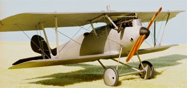
Final images taken today. I wrap this up in a couple of days.
JackFlash
Joined: January 25, 2004
KitMaker: 11,669 posts
AeroScale: 11,011 posts
Posted: Monday, September 17, 2007 - 09:32 AM UTC
Greetings all: Here is a bit of a teaser.
JackFlash
Joined: January 25, 2004
KitMaker: 11,669 posts
AeroScale: 11,011 posts
Posted: Monday, September 17, 2007 - 01:39 PM UTC
Greetings all;
By the count of hits we are getting I am guessing you are enjoying this thread. But all good things must. . . well you know. Over the next two days I'll be uploading the last images and putting finishing touches on the front page "Review." I posted the link for this thread off to Roden and have gotten a very nice e-mail from them with their admiration.
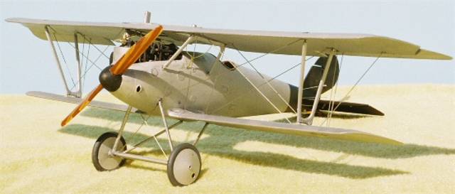
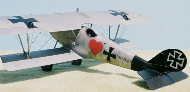
Here I will discuss a bit about finish. Now we have a thread on this subject here at the Early Aviation title, but people don't always use the search engine. So for this build I'll touch on this subject. For this specific scheme I don't have too many concerns. I portrayed it as it might have looked at the end of its service career in Jasta 16b. Greg VanWyngarden believes it was later assigned to a Jastaschule (fighter school) where it was photographed.
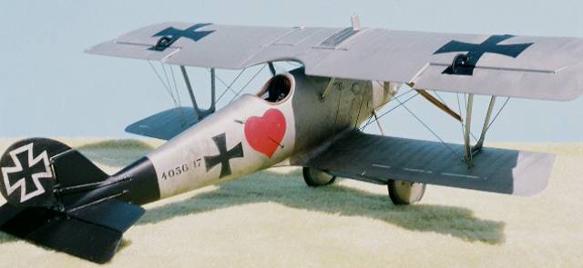
The exhaust stains follow the path down the fuselage right side where it drops under the fuselage at the lower wing's trailing edge and wraps around the belly and up around the pilots left side. Usually after each patrol this was cleaned up by the ground crew but it tended to stain the surface of the silbergraü - aluminum dope finish. It has been recorded that these finishes were either sprayed or brush painted at the factory.
Also I have tried to show the difference between the fabric coverings on various areas of the airframe. For instance the top wing center section and fuselage are wood covered then fabric covered. The wings are wood framing with the fabric spanning the open bays in between the ribs. While some like a cleaner model I like the look of the originals and usually that is where my mind is at during the build process.
German propellers were usually altering laminations and either clear or dark varnishes were applied. These high gloss items tended to go to a more semi gloss but never a flat finish.
Generally speaking part of the aircraft package that went to the front were spare parts for components that tended to need repair or replacement on a regular basis. Propellers , magnetos , pumps and etc. These were all tagged with the aircraft serial number. Larger components that were damaged and needed to be repaced where manufactured or added from spares at the Flugpark (air depot) level.
Ailerons, elevators and rudders were all done at the locat Jasta level. Often times even engine repairs were carried out there as well.
By the count of hits we are getting I am guessing you are enjoying this thread. But all good things must. . . well you know. Over the next two days I'll be uploading the last images and putting finishing touches on the front page "Review." I posted the link for this thread off to Roden and have gotten a very nice e-mail from them with their admiration.
Here I will discuss a bit about finish. Now we have a thread on this subject here at the Early Aviation title, but people don't always use the search engine. So for this build I'll touch on this subject. For this specific scheme I don't have too many concerns. I portrayed it as it might have looked at the end of its service career in Jasta 16b. Greg VanWyngarden believes it was later assigned to a Jastaschule (fighter school) where it was photographed.
The exhaust stains follow the path down the fuselage right side where it drops under the fuselage at the lower wing's trailing edge and wraps around the belly and up around the pilots left side. Usually after each patrol this was cleaned up by the ground crew but it tended to stain the surface of the silbergraü - aluminum dope finish. It has been recorded that these finishes were either sprayed or brush painted at the factory.
Also I have tried to show the difference between the fabric coverings on various areas of the airframe. For instance the top wing center section and fuselage are wood covered then fabric covered. The wings are wood framing with the fabric spanning the open bays in between the ribs. While some like a cleaner model I like the look of the originals and usually that is where my mind is at during the build process.
German propellers were usually altering laminations and either clear or dark varnishes were applied. These high gloss items tended to go to a more semi gloss but never a flat finish.
Generally speaking part of the aircraft package that went to the front were spare parts for components that tended to need repair or replacement on a regular basis. Propellers , magnetos , pumps and etc. These were all tagged with the aircraft serial number. Larger components that were damaged and needed to be repaced where manufactured or added from spares at the Flugpark (air depot) level.
Ailerons, elevators and rudders were all done at the locat Jasta level. Often times even engine repairs were carried out there as well.
JackFlash
Joined: January 25, 2004
KitMaker: 11,669 posts
AeroScale: 11,011 posts
Posted: Monday, September 17, 2007 - 07:20 PM UTC
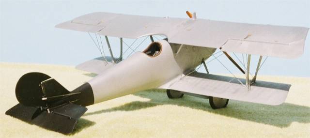
Here is the engine. The cowling panels were cut away and a lip area added to the fuselage. This was blended in and attachment holes added. To be accurate I should simulate snap twist fittings.
 |

WEB HOSTING BY


Copyright ©2021 AeroScale and Kitmaker Network, a subsidiary of Silver Star Enterprises
All Rights Reserved. Please read our Conditions of Use and Privacy Policy.
All Rights Reserved. Please read our Conditions of Use and Privacy Policy.