World War II
Discuss WWII and the era directly before and after the war from 1935-1949.
Hosted by Rowan Baylis
1/72 MPM Bristol Blenheim mk.I
Emeritus
_VISITCOMMUNITY
Uusimaa, Finland
Joined: March 30, 2004
KitMaker: 2,845 posts
AeroScale: 1,564 posts
Posted: Saturday, July 12, 2008 - 02:00 AM UTC
Great progress this time. I've even started laying down some paint on this bird!

As I got the engine components done, I started painting on them.
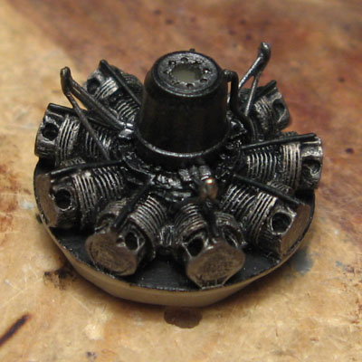
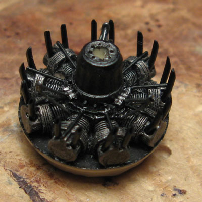
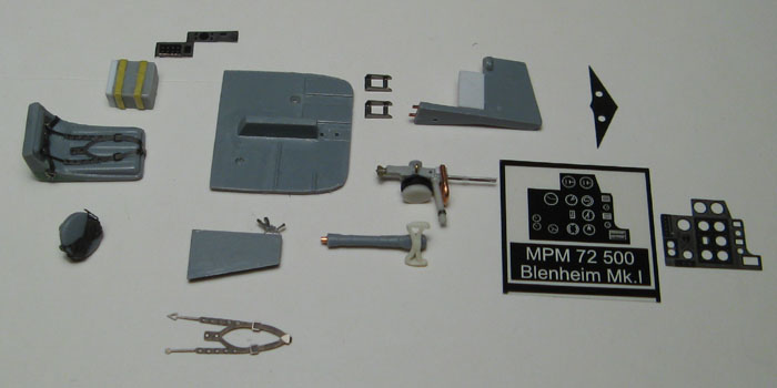
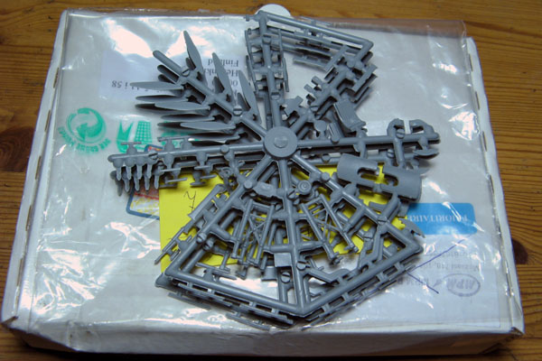
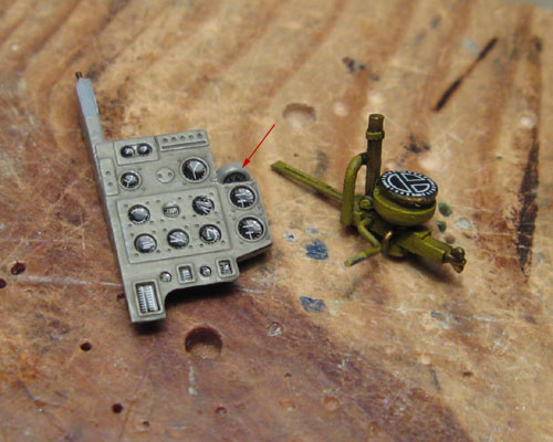
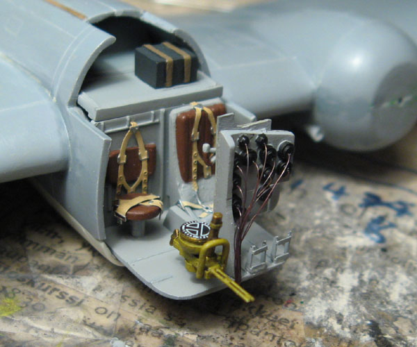
Here's the parts for one engine (excluding parts going to the exterior of the cowling):

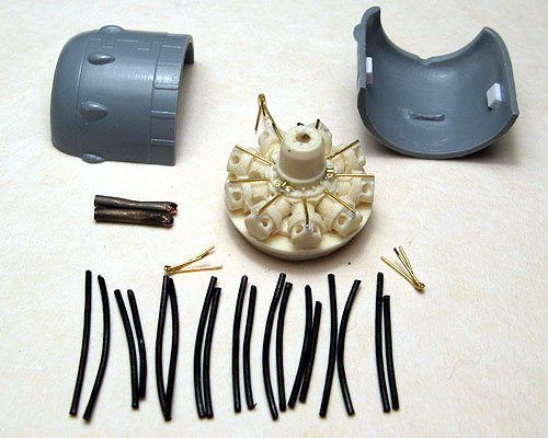
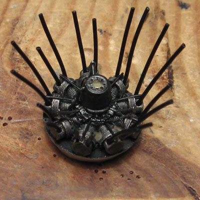
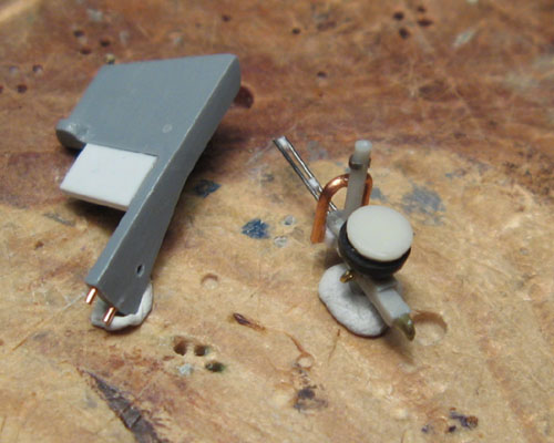
The 18 black tubes are the exhaust pipes that will go between the engine cylinders and the exhaust collector ring. That's cord from a broken computer mouse with the wires inside removed. The idea is that they should line up correctly when just glued to the holes drilled at a slight outward angle in the engine cylinders and trimmed to the right length.
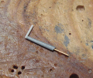
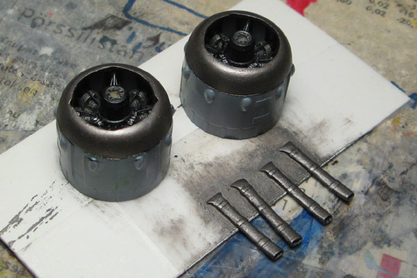
The two air intake pipes are steel tubing from some electrical parts, annealed over a lighter flame to ease bending to the right shape. The resulting scorched color looked so nice I decided no to paint the pipes at all.
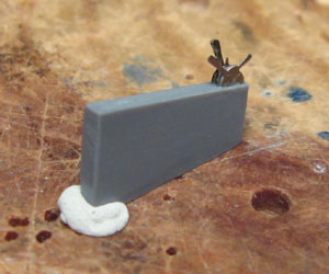
The three triangular exhaust collector ring supports were quite tricky to make, even though I made the decision to make them from two pieces of brass wire instead of the realistic three. That turned out to be a good choice, as even these simplified ones were quite tedious and hard to make, individually dryfit and trim to the right length. Now I have them all marked so I'll know which one goes to which engine and which place.


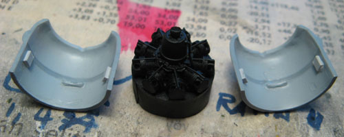
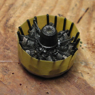
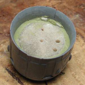
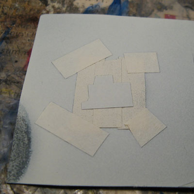
The engines received a black primer coat and the insides of the cowlings a light grey, some mr. surfacer 1000, which happens to be quite similar to the light grey interior paint on the real thing.
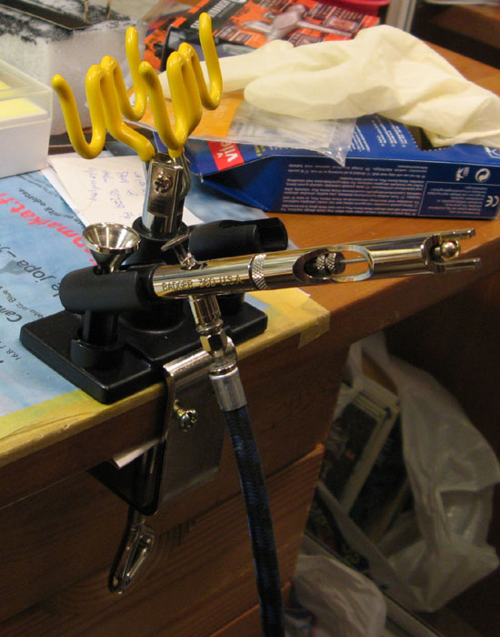
Obviously, the black from a spray can didn't cover all the nooks and crannies of the engines, so I finished the priming with my airbrush to avoid filling up all the lovely details.

And now for something completely different...
A blast from the past.

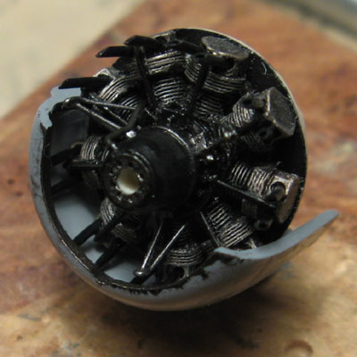
For drybrushing the engines, I dug out some humbrol enamels, as they dry slower and their metallics' smaller pigment size is better suited for this smaller scale.
That smell of paint and mineral spirits was quite nostalgic. The drawback: I have to wait around the usual six hourse before I can continue with the details.


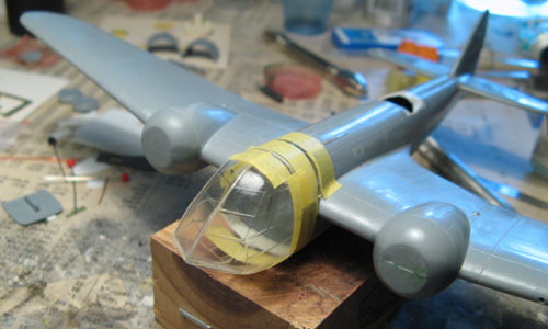
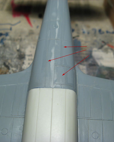
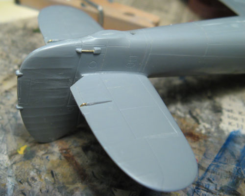
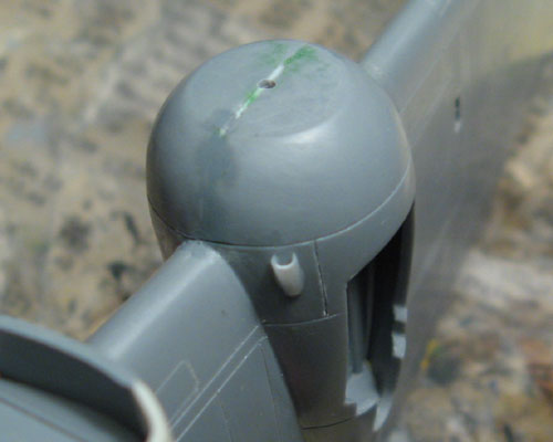
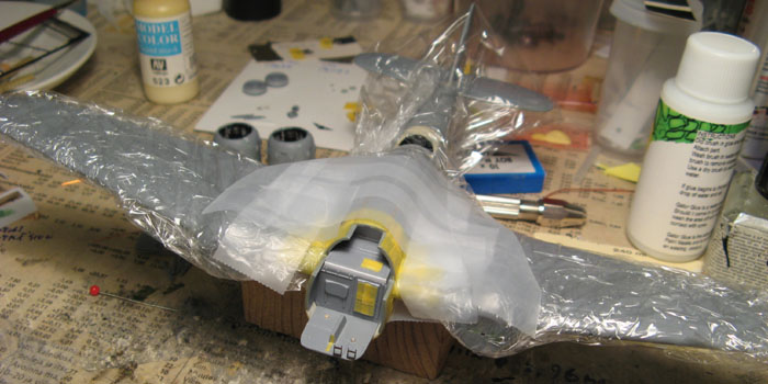
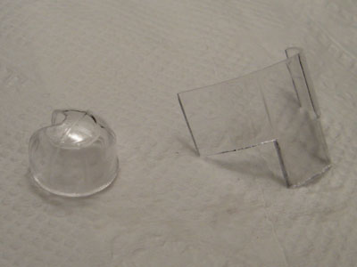
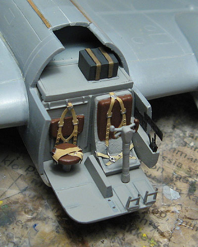
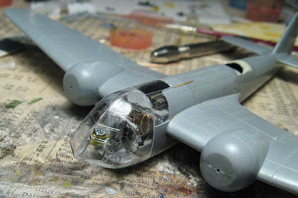
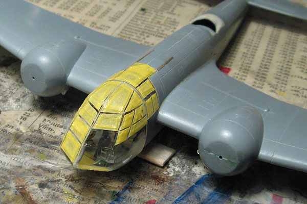
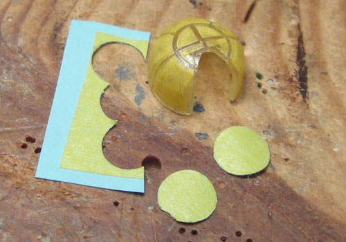
This was another small victory. I managed to get the cockpit glazing to fit without steps in the seam with the fuselage. The only was to sand the gluing surfaces going down in the middle of the glazing, quite a daunting task at first, but it wasn't that tricky in the end. The main concern was to keep the meeting edges straight, take care not to scratch the parts and keep from sanding too much.
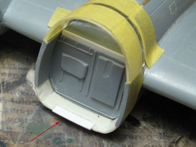
With the glazing fitting nicely, I glued a strip of styrene to the bottom edge of the fuselage opening to help gluing on the glazing straight and to reinforce the seam.


Next I'll go back to the engines.
My next update should be just around the corner.
Emeritus
_VISITCOMMUNITY
Uusimaa, Finland
Joined: March 30, 2004
KitMaker: 2,845 posts
AeroScale: 1,564 posts
Posted: Wednesday, July 16, 2008 - 03:16 AM UTC
I got the engines done.

Here's one with the exhaust collector ring supports installed:

I also tried out the new Citadel washes on the engines, in this case the dark brown / mud wash, the actual name of which escapes me now. Seems like these are everything GW's earlier inks were not. Quite superb. The color density is just right, they flow well and don't stick immediately leaving ugly stains and spots like the inks.

Then it was time to attach the exhaust pipes themselves.
I tried a method recommended by a fellow modeler. Instead of styrene rod, solder wire or other material requiring careful trimming and shaping, I used flexible electrical cord from a broken PC mouse, with the copper wire inside removed.
Each cylinder got two pipes.

I then measured the approximate length required and used masking tape to help cutting the pipes to the right length.


This is how they would fit within the cowling.


The last thing I did before assembling the cowlings was trimming the back sides of the pipes to make them line up snuggly and convincingly.


With the small blocks of styrene glued inside the cowlings, putting them together with the engines went smoothly. After the glue had dried, I secured the somewhat loosely fitting engines by stuffing milliput to the seams.

Notice the cowling flaps?
Although I had plans to replace the overly thick cowling flaps with scratch-built items, I decided not to go for it, as I have the campaign deadline looming ahead, and the flap detail in the kit parts was pretty nice. So I simply thinned the edges with a knife and some sandpaper.

Until next time.
dcandal
_VISITCOMMUNITY
Buenos Aires, Argentina
Joined: September 07, 2006
KitMaker: 918 posts
AeroScale: 688 posts
Posted: Wednesday, July 16, 2008 - 02:24 PM UTC
A wonderful job you are making
Emeritus
_VISITCOMMUNITY
Uusimaa, Finland
Joined: March 30, 2004
KitMaker: 2,845 posts
AeroScale: 1,564 posts
Posted: Tuesday, July 29, 2008 - 01:18 AM UTC
Thanks.

Some more slowish progress this time:


The underside was missing a few panel lines and the incendiary / recon camera bay door, which scribed there.


And here's the trim tab actuator rods glued in.
Emeritus
_VISITCOMMUNITY
Uusimaa, Finland
Joined: March 30, 2004
KitMaker: 2,845 posts
AeroScale: 1,564 posts
Posted: Thursday, July 31, 2008 - 02:08 AM UTC

The kit pitot tube required some work because of the mold-misalignment. The actual pitot head couldn't be cleaned up properly, so I replaced it with stretched sprue. The other end needed a few swipes from a file to fix gluing surface. I wasn't thrilled of the idea of a simple butt-joint, so I drilled a hole to the end and glued in a length of brass rod to make a more robust joint.


Talking of brass rod, here's some glued to the control surfaces to make trim tab actuators etc.


Spending a moment working on cockpit components, I sliced off the blob of plastic representing the throttle quadrant and made a better-looking part from left-over PE parts.

While casually glancing through my references, I noticed that there is an intake scoop in the engine nacelles that I wasn't aware of (I later learned belong to the heating system used in Finnish-built & improved Blenheims). Seems MPM missed them too - understandable as they likely designed the kit to represent an original British example - the kit parts didn't include them.

The two scoops were easily fashioned from styrene rod and glued in place with liquid cement.

That's it for this update. Until next time.
chukw1
_VISITCOMMUNITY
California, United States
Joined: November 28, 2007
KitMaker: 817 posts
AeroScale: 729 posts
Posted: Friday, August 01, 2008 - 03:53 AM UTC
Continuing excellence! It's shaping up quite nicely, and your attention to minute detail matches the care you've given to larger components. Cheers!

chuk
Emeritus
_VISITCOMMUNITY
Uusimaa, Finland
Joined: March 30, 2004
KitMaker: 2,845 posts
AeroScale: 1,564 posts
Posted: Saturday, August 02, 2008 - 07:50 AM UTC

Quoted Text

Continuing excellence! It's shaping up quite nicely, and your attention to minute detail matches the care you've given to larger components. Cheers!

chuk


Thanks, much appreciated.
Glad you like it.
Same goes for your helldiver build. Simply amazing detailing and craftsmanship inside and out.
Can't wait to see it finished.

I hope to get the cockpit interior finished soon and move over to the main landing gear.
Emeritus
_VISITCOMMUNITY
Uusimaa, Finland
Joined: March 30, 2004
KitMaker: 2,845 posts
AeroScale: 1,564 posts
Posted: Tuesday, August 05, 2008 - 02:56 AM UTC
Now I think it's about time to call this cockpit done and ready for painting.


Yes, you saw correctly, I just had to cobble together a wimperis bombsight from various left-overs, styrene rod as well as brass & copper wire...

It's far from perfect or accurate, but it should give an idea of a bombsight and fill the bombardier's side of the cockpit when finished.

Okay, to be perfectly honest, the cockpit's **almost** done, as I'm still not sure whether to add a folding forward seat for the bombardier, as seen in a photo here.
The problem is that my references don't seem to have any specific information whether these Finnish-built blenheims had these folding seats or not. In one book I'm using, there's a photo of a Mk.I blenheim's cockpit from above, clearly showing the seat. In the caption it only says it's one of the aircraft bought from England, and the cockpit differing slightly from the ones built in Finland, nothing more.
All the photos of domestically built Blenheims seem to be from the outside. I guess I'll take another good look at them for the seat.

Almost forgot, there's one more detail I just have to add to the cockpit.
That's the air conditioning. In this plane, it's just a pipe going from the tip of the nose to the triangular PE part attached inside the canopy. No mention of this in the instructions either. Being such quite a prominent detail, I think this is a must-have.


That's all folks for this update.
guitarlute101
_VISITCOMMUNITY
West Virginia, United States
Joined: December 18, 2006
KitMaker: 1,121 posts
AeroScale: 1,063 posts
Posted: Tuesday, August 05, 2008 - 04:29 AM UTC


Excellent work. Can't wait to see more.

Mark
Emeritus
_VISITCOMMUNITY
Uusimaa, Finland
Joined: March 30, 2004
KitMaker: 2,845 posts
AeroScale: 1,564 posts
Posted: Tuesday, August 05, 2008 - 07:36 AM UTC
Want some more?
Well, not exactly progress, but look what the postman brought today:

The replacement parts from MPM arrived. I humbly asked for three copies of the main landing gear parts, and they sent me three whole sprues. Now that's what I call customer support!

These are indeed much better moulded than the sprue in my sample. No scratch-building the landing gear!
(and a healthy pile of parts to the spares box too)
jaypee
_VISITCOMMUNITY
Scotland, United Kingdom
Joined: February 07, 2008
KitMaker: 1,699 posts
AeroScale: 1,384 posts
Posted: Tuesday, August 05, 2008 - 09:21 AM UTC
Funny last week Eduard sent me 3 copies of RFC crew because one of the heads was missing.
Enough for a whole wing!
Gotta love Czech customer support. I think I'll move there.
Just shows how cheap it must be to turn out injection mould parts once you got the toolings.
lampie
#029
_VISITCOMMUNITY
England - East Midlands, United Kingdom
Joined: December 23, 2005
KitMaker: 6,249 posts
AeroScale: 3,270 posts
Posted: Tuesday, August 05, 2008 - 11:19 AM UTC
Hi Eetu!
Its good to see your continued progress on this, and now with the help of MPM too!
Great customer service!
I emailed them once asking about a spare part, and recieved a reply almost straight away,although they werent able to help in that instance.
I see that theres a Blenheim IV just gone on show at the Aviation Museum Of Central Finland in Tikkakoski. I dont suppose thats in Helsinki, as I think I have a day off there in December?
What markings will your Blenhiem be wearing?
Nige
Emeritus
_VISITCOMMUNITY
Uusimaa, Finland
Joined: March 30, 2004
KitMaker: 2,845 posts
AeroScale: 1,564 posts
Posted: Tuesday, August 05, 2008 - 11:47 PM UTC

Quoted Text

Hi Eetu!
Its good to see your continued progress on this, and now with the help of MPM too!
Great customer service!
I emailed them once asking about a spare part, and recieved a reply almost straight away,although they werent able to help in that instance.
I see that theres a Blenheim IV just gone on show at the Aviation Museum Of Central Finland in Tikkakoski. I dont suppose thats in Helsinki, as I think I have a day off there in December?
What markings will your Blenhiem be wearing?
Nige


Thanks.
I'll hopefully get the cockpit and landing gear together soon so I can start painting this thing.

You're correct, the Aviation museum of central Finland isn't located in Helsinki.
Check out their website for driving instructions and such: http://www.k-silmailumuseo.fi/?action=etusivu
Indeed, the newly restored Blenheim mk.IV, BL-200 has just recently been set up for display in the museum.
There's a blog about the restoration project. It can be found here:
[urlhttp://www.ilmasotakoulunkilta.fi/IlmaSK/ilmaskmma.nsf/sp?Open&cid=Content9993D[/url]
The blog is also available in English, link is on the top of the page on the right.
Now they seem to have the entire blog for downloading as a single PDF file, but it seems to be the finnish version, at least for now.

On the markings, I'm thinking about doing BL-158, as there's some good photos of it in my references. The resin bomb bay limits my choices to the Finnish-manufactured II-series. BL-157 is another tempting choice, as it happens to be the plane in the box top photo.
Emeritus
_VISITCOMMUNITY
Uusimaa, Finland
Joined: March 30, 2004
KitMaker: 2,845 posts
AeroScale: 1,564 posts
Posted: Monday, August 11, 2008 - 02:11 AM UTC
I'm painting now.

Now I've primed the interior components and other detail parts, excluding the landing gear, which I'm still working on.
I won't bore you with pics of primed parts on cocktail stick and taped to pieces of cardboard, but here's the cockpit, masked and ready for priming:

Even though I could have primed the whole airframe at the same time, I went this way. I'll later prime the whole thing with the canopy in place and masked, as Mr surfacer is close enough for the insides of the canopy frames.
In case you're wondering, that's ordinary plastic wrap (cling film) I used for the majority of the airframe.


Instead of the painting the instrument panel, I've recently started to paint the back side of the acetate instruments. The only possible pitfall is the possibility of accidentally painting the wrong side. Triple check, then check again twice before painting.

I also started preparing the clear parts by dipping the rear cockpit glazing and the rear turret dome in future.


I think it'll be best to dip the main cockpit greenhouse when the two halves are the triangular PE part and ventilation tube are finished, dryffited and ready to be attached inside.

To close this update, say hello to my little new friend (airbrush holder, not the airbrush):

I really don't know how I managed so far without an airbrush holder. It sure eases airbrushing when you have a proper holder on your desk.

Next time you'll see some painted interior components.
AirLedge
_VISITCOMMUNITY
Cork, Ireland
Joined: July 26, 2007
KitMaker: 292 posts
AeroScale: 265 posts
Posted: Tuesday, August 12, 2008 - 06:18 AM UTC
Nice build. Gotta get me one of those holders ...
magnusf
_VISITCOMMUNITY
Stockholm, Sweden
Joined: May 02, 2006
KitMaker: 1,953 posts
AeroScale: 1,902 posts
Posted: Tuesday, August 12, 2008 - 07:14 PM UTC
Still keeping an eye on you Eetu even if I haven't been very active at the building table myself lately! Nice scratch work, that sight is awesome and your work on the engines is top class.


Magnus
Emeritus
_VISITCOMMUNITY
Uusimaa, Finland
Joined: March 30, 2004
KitMaker: 2,845 posts
AeroScale: 1,564 posts
Posted: Friday, August 15, 2008 - 01:51 AM UTC
Thanks for the compliments.

I got the cockpit together now!

I may add some wear, grime and dust, but basically it's done now.

Of course, it's still missing the instrument panel and bombsight, which are ready to be installed as I'm writing this.
Here's them still on the loose.

For the instrument panel, I mixed medium sea grey (which I used for the rest of the cockpit) with 50% vallejo's iraqi sand to make a more beige color.
The instrument panels in the Finnish-built aircraft were slightly different than the British, but I didn't try any modifications on this one.
To finish them off, I applied future to the instruments to simulate glass and added a segment of some left-over flight instrument decal to represent the compass (pointed by the arrow). The bombsight also received a decal.

Next I'll figure out how to pull of the ventilation tube, then put together the greenhouse canopy.
Emeritus
_VISITCOMMUNITY
Uusimaa, Finland
Joined: March 30, 2004
KitMaker: 2,845 posts
AeroScale: 1,564 posts
Posted: Saturday, August 16, 2008 - 03:01 AM UTC
Okay, now the cockpit's done:

Notice that the wiring of the instruments is not accurate, in reality they would go under a panel in the side. I ran them under the floor because I reasoned the cockpit glazing halves are best assembled on their own, then attached to the airframe. And even if I glued in the left half first, the wires would be extremely tricky to install properly anyway.

Talking of inaccuracies, my choice of blanking off the cockpit with styrene sheet turned out to be a wrong one. In the real thing the cockpit was open to the rear, and the semicircular raised area in the shelf part was supposed to represent half of the "wing tub", a void space going through the whole wing in the fuselage.
Well, at least it helps keep the dust out of the cockpit in the finished model.
lampie
#029
_VISITCOMMUNITY
England - East Midlands, United Kingdom
Joined: December 23, 2005
KitMaker: 6,249 posts
AeroScale: 3,270 posts
Posted: Saturday, August 16, 2008 - 03:45 AM UTC
Your making a great job of this Eetu.
Im really enjoying watching the progress
Nige
Emeritus
_VISITCOMMUNITY
Uusimaa, Finland
Joined: March 30, 2004
KitMaker: 2,845 posts
AeroScale: 1,564 posts
Posted: Saturday, August 23, 2008 - 04:21 AM UTC
Glad to hear people are enjoying.

Now it's finally starting to come together.
.
.
.
*Drum roll*
.
.
.
We have an enclosed cockpit!


Careful preparation really paid off when gluing the canopy parts. As I was mainly using normal styrene cement (revell's liquid one, with the needle applicator, if it's of use for anyone) to ensure good bonds, I took the time to mask the clear window portions of the parts prior to bringing out the glue.
After gluing the halves of the main glazing toghether, I gave it a dip in floor wax. Although the parts didn't have much room for further improvement, it gave them some extra shine and clarity.
After letting the future coating dry, I attached the air conditioning tube made from styrene rod to the inside tip of the glazing using gator glue. I made the decision of not using the triangular PE part that was meant to be glued inside the canopy. It just didn't want to fit (I don't know if it's because the glazing halves were sanded or not), and if I managed to get it fit, gluing it in place would have been tricky and the risk of getting glue stains on the clear windows very high.

No big surprises when attaching the canopy. Thanks to my cutting, filing and sanding earlier, the rear portion was a drop-fit. The main glazing initially sat too low. It was caused by the strip of styrene I had glued to the lower edge of the bomb bay, and solved by filing it down until the fit was fine. After masking up again, I used the same styrene cement (on styrene to styrene) and gator glue (for styrene to resin) for gluing. Of course, the gluing surfaces had to be lightly sanded prior to gluing to remove future so styrene cement could work properly.

Next I'll mask the glazing before attaching the engine nacelles. Then the airframe's done and ready for priming.


PS.
Almost forgot this. I need your opinions on this one. How would you do this grille detailing on the intake scoops that go the cowlings?
They were moulded solid in the kit so I opened them up.

Here's what I'm looking for:


Left-over PE came to my mind first, but precisely cutting slots into tiny parts would be all but impossible. Also, only the "half-thickness" PE would be thin enough, or so I presume. And there's less of that stuff around on frets.
How about paper? I think it would be easier to cut, and it could be hardened by applying superglue.
What do you think?
chukw1
_VISITCOMMUNITY
California, United States
Joined: November 28, 2007
KitMaker: 817 posts
AeroScale: 729 posts
Posted: Saturday, August 23, 2008 - 04:48 AM UTC
I'm working on the transparencies of the Helldiver now and can empathize. For me it's the wiggliest part of a build- no room for error! Your chisel-nosed bird is shaping up so nicely- it's hard to believe it's 1/72. Cheers!

chuk
Murdo
_VISITCOMMUNITY
Scotland, United Kingdom
Joined: May 25, 2005
KitMaker: 2,218 posts
AeroScale: 211 posts
Posted: Saturday, August 23, 2008 - 12:24 PM UTC

Quoted Text

I tried a method recommended by a fellow modeler. Instead of styrene rod, solder wire or other material requiring careful trimming and shaping, I used flexible electrical cord from a broken PC mouse, with the copper wire inside removed.


May I humbly ask how you removed the internal wire without damaging the external plastic sir?

Emeritus
_VISITCOMMUNITY
Uusimaa, Finland
Joined: March 30, 2004
KitMaker: 2,845 posts
AeroScale: 1,564 posts
Posted: Saturday, August 23, 2008 - 11:42 PM UTC

Quoted Text


Quoted Text

I tried a method recommended by a fellow modeler. Instead of styrene rod, solder wire or other material requiring careful trimming and shaping, I used flexible electrical cord from a broken PC mouse, with the copper wire inside removed.


May I humbly ask how you removed the internal wire without damaging the external plastic sir?


Sure. Basically by peeling a bit of the plastic shell at one end and pulling out the innards with pliers or tweezers.
Shorter pieces were easier to do, so I cut the cord into smaller pieces first.
Emeritus
_VISITCOMMUNITY
Uusimaa, Finland
Joined: March 30, 2004
KitMaker: 2,845 posts
AeroScale: 1,564 posts
Posted: Sunday, August 24, 2008 - 07:25 PM UTC
Masking is fun. Masking is fun. Masking is fun...


And the fun continues with the turret.

Next I'll paint the cowling rings, mask them and attach the cowlings to the wings. Then it's about time for priming.
Emeritus
_VISITCOMMUNITY
Uusimaa, Finland
Joined: March 30, 2004
KitMaker: 2,845 posts
AeroScale: 1,564 posts
Posted: Friday, August 29, 2008 - 03:06 AM UTC
Another hour or so I spent masking the turret dome.

A perforator was a great help in masking the curved parts. Luckily, the one I found around the house was just the right size.


I reasoned the exhaust collector rings would be tricky to mask and paint if the cowling were attached, so I painted them at this point.
I masked out the rest of the cowling, sprayed a black primer and then drybrushed with two burnt metallic mixes with a black wash in between. Quite a nice shade I think, if a little fresh and clean. But those shouldn't be too hard to blacken some more later if needed I suppose.

That's it for now, more updates coming soon (enough).