_GOTOBOTTOM
Rotary Wing
Discuss helicopters and other rotary wing aircraft from any era.
1:32 MBB BO 105 Stretch
grubbyfingers
_VISITCOMMUNITY
Victoria, Australia
Joined: September 07, 2007
KitMaker: 404 posts
AeroScale: 339 posts
Posted: Monday, March 17, 2008 - 12:28 PM UTC
Hi Guys,

I'm back again. I have actually started another build, stretching a Revell BO 105 into a 105CBS.

Here we go ...

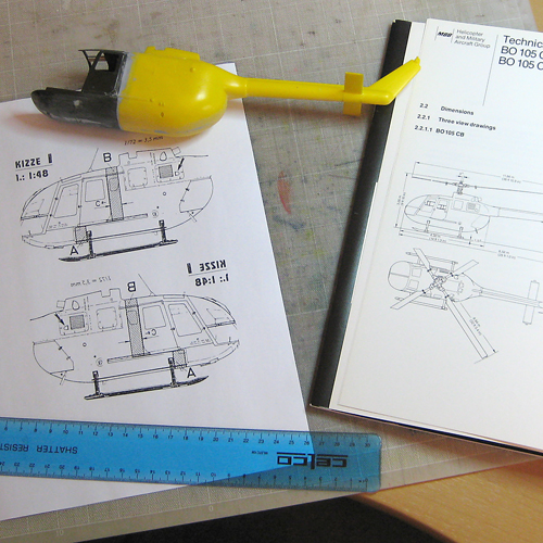
1:32 MBB BO105CBS Build


Here’s a how I built an MBB BO 105CBS from a couple of Revell 1:32 scale kits. This would work just as well for any of the 1:72 or 1:48 kits around, I just like ‘em big.

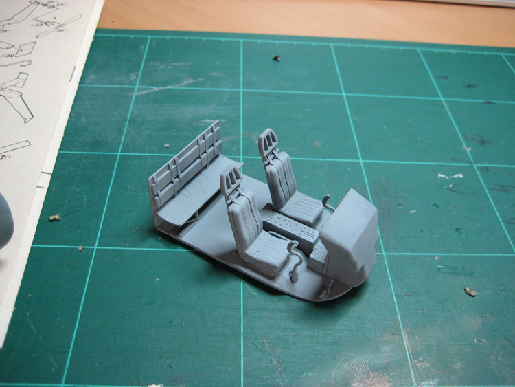
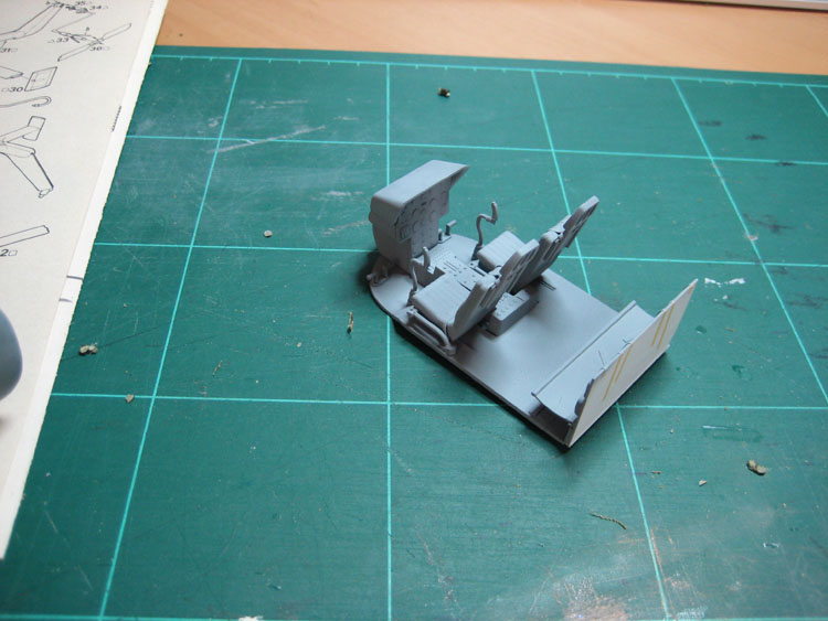
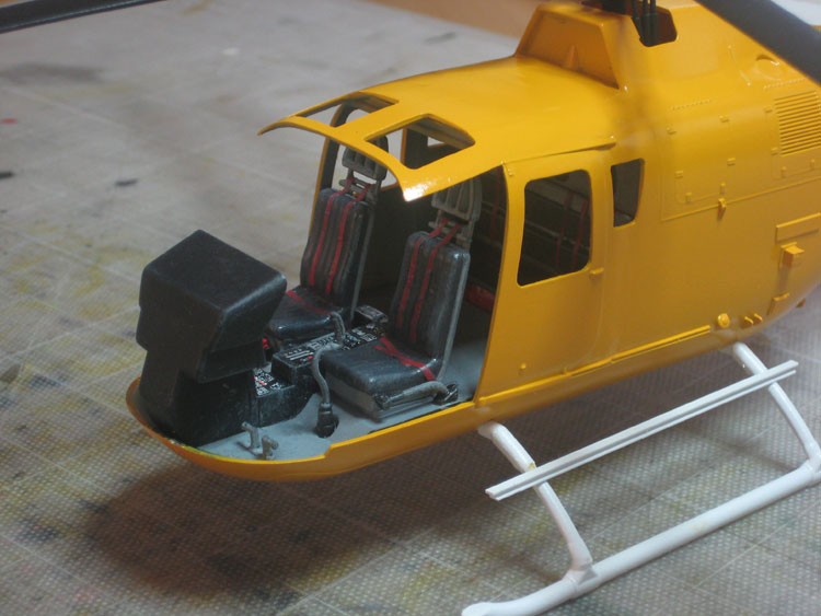
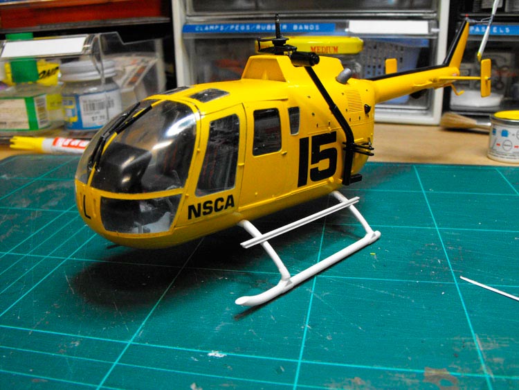
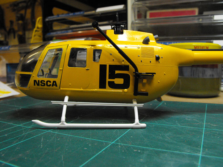
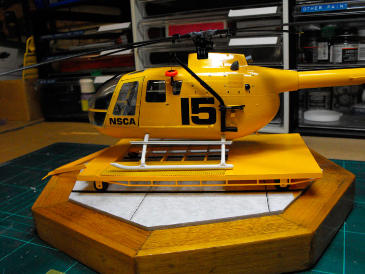
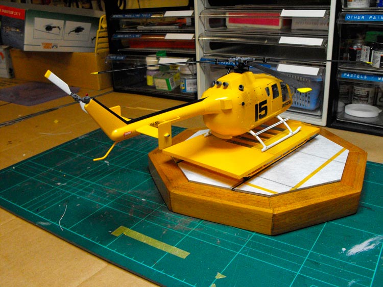
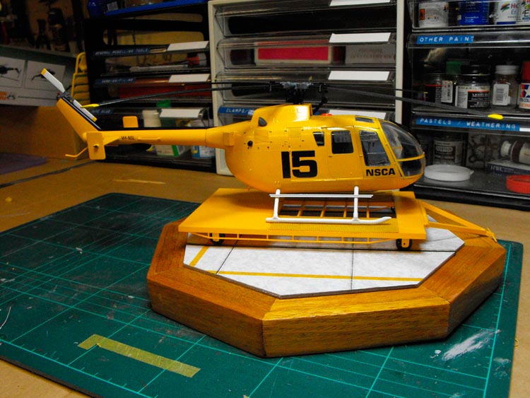
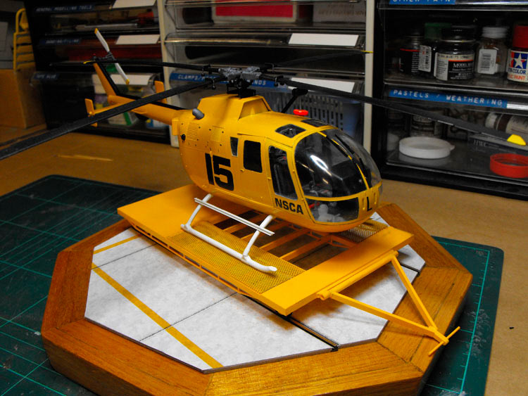
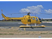
All the Revell and Italeri 1:32 BO 105 kits are for the standard short fuselage version. The donor kits for this bash were the Revell ADAC triple-pack that has the 105, a BK 117 and a n EC 135, and the standalone Revell BO 105 PAH anti-tanker. The 105CBS version has an additional 8 inches length in the cabin. This was done so it could take the larger American rescue litters. There are some detail differences, which I will cover later, and a few additions to make the particular subject I am modelling here. This project is a BO 105CBS, c/n: S-615, VH-NSL, that was operated by the National Safety Council Australia (Victorian Division) (NSCA) in the mid 1980s. It was not ever used in the rescue role, so the internal fitout was quite basic, just the rear seats, no stretchers, no medical gear. It was, however, fitted with an external rescue winch.

Stretching the Fuselage

This looks to be a fairly easy excersize as far as fuselage stretches go, but it is my first attempt, so let’s see what happens! You need to add about 7.8mm to the fuselage length and the fuselage is constant in section where the stretch occurs. This extension was done on the full size chopper in the simplest way possible. The extension below the floor was made ahead of the landing gear, so the landing gear attachments stayed standard. Above the floor the extension was made at the rear end of the cabin, again changing as little as possible. An extra rear window was added in the extension and this third window is the easiest way to pick the difference between the stretched and standard airframes.

You could probably do this stretch with an insert made from plastic card, but that sounds like too much work!

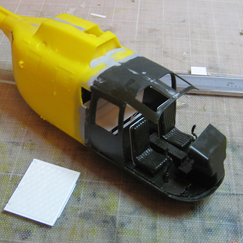
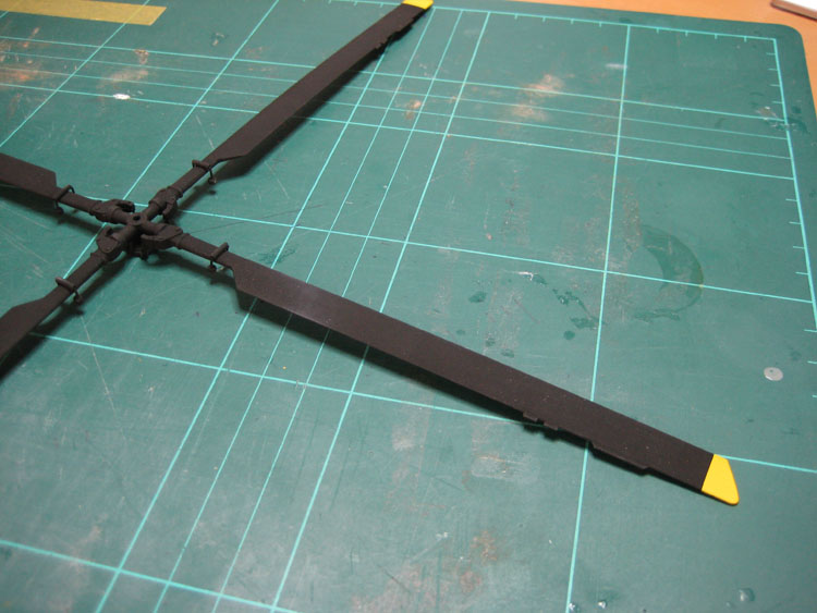
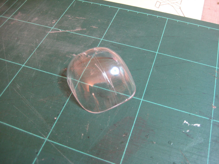
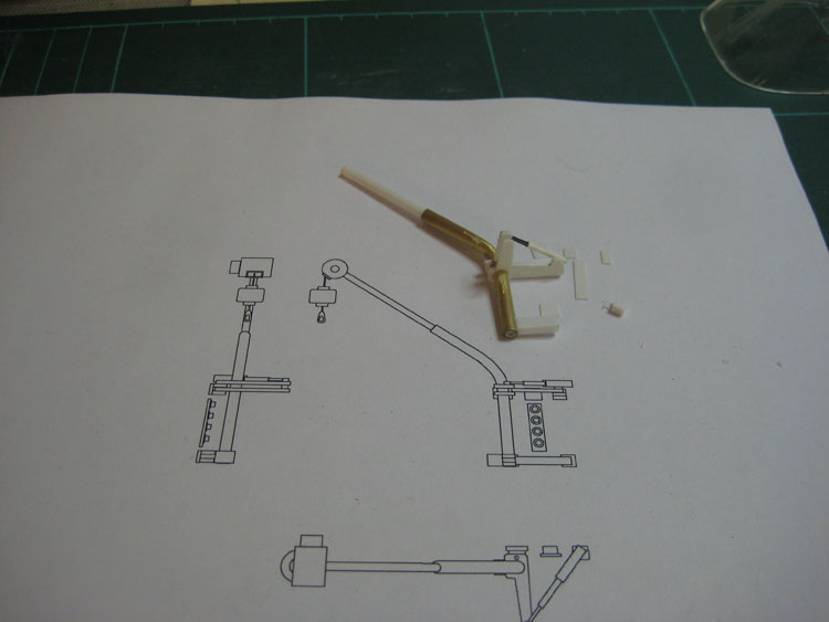
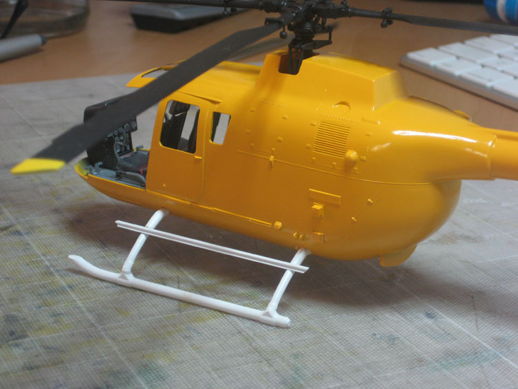
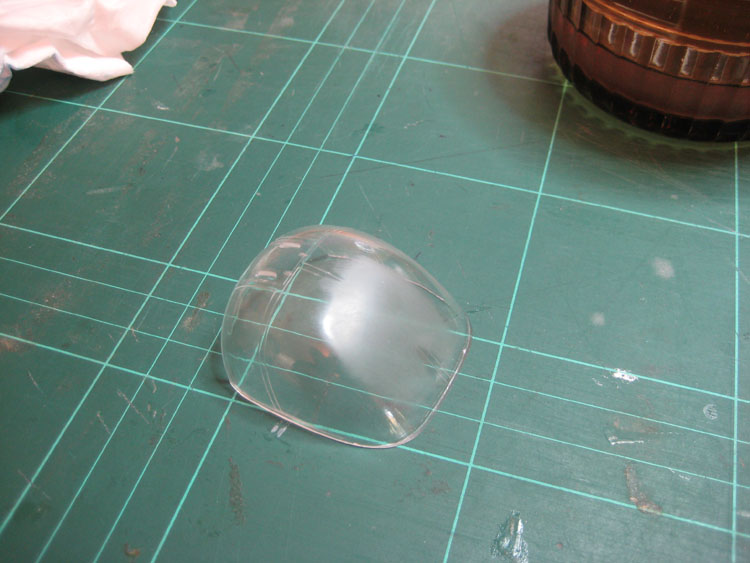
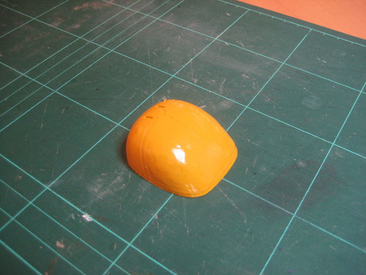
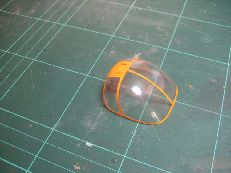
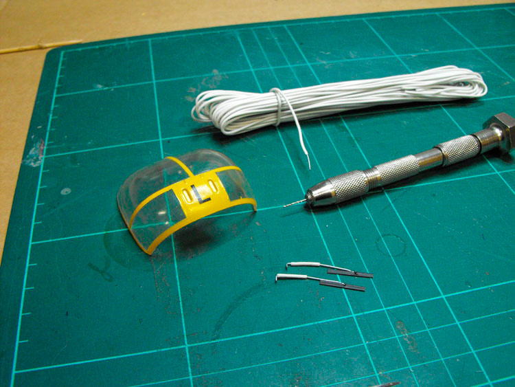
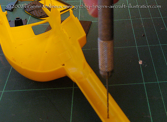
With the large, single piece, nose transparency, it is possible to finish the fuselage first and then slide the interior in afterward. This is a huge advantage as you don’t need to finalise the interior first-up and you can also do the meaty work on the fuselage, even the painting, without fear of damaging a delicate interior. For this reason, and because it was my first stretch, I tackled the fuselage first. As per the instructions, I drilled out the holes for the “grab-handle” antennae on the tail boom.


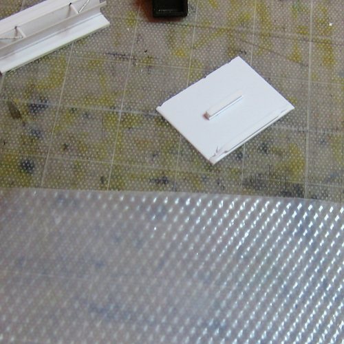
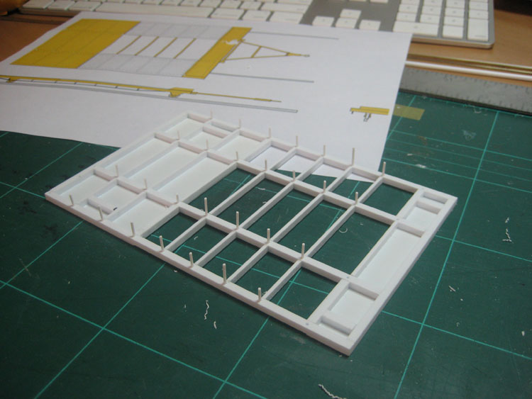
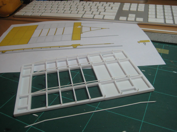
The gearbox bulkhead and floor can go in and I also glued in the rear cabin bulkhead. The PAH rear bulkhead had some nice quilted detail, but a hole at the bottom, so I doubled it up with a spare bulkhead to blank off the hole and give even more stiffness. As an extra precaution I added some plastic card to the fuselage join to make it all good and solid for when I started cutting. I did this to both fuselages.


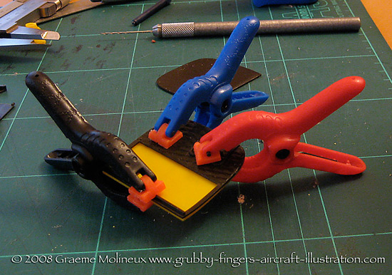
The fuselage halves are now glued together, clamped up and left to cure.


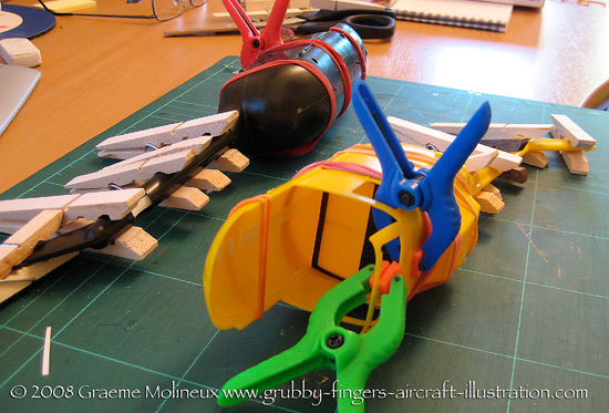
Now comes the interesting part - the cut-and-shut. Deep breath and away we go ...
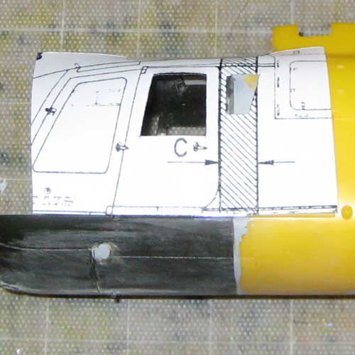
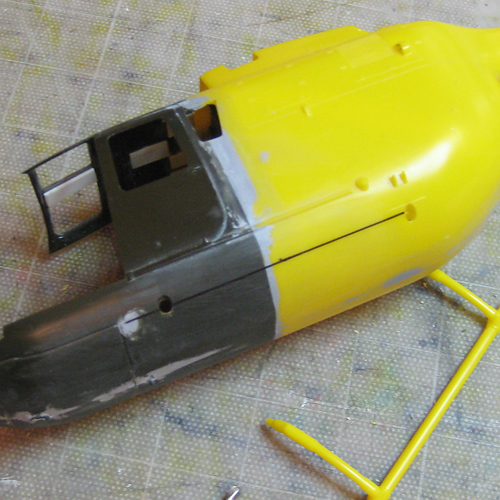
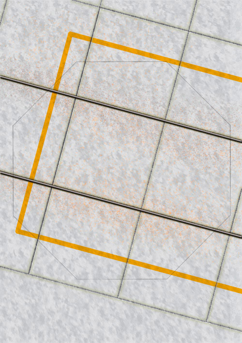
With my two fuselages assembled and thoroughly cured I set about marking up the cut. I decided to simplify the stretch even further. Rather than cut and shut two sections, as per the original, above and below the floor, I made a single cut right through one section of the fuselage and re-drilled the front landing skid mounting holes. This way I am just trying to butt two cylinders together rather than trying to align several loose pieces. I’ll keep the rear cabin doors shut to ease the process further.
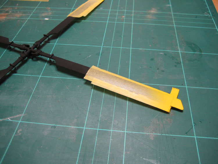
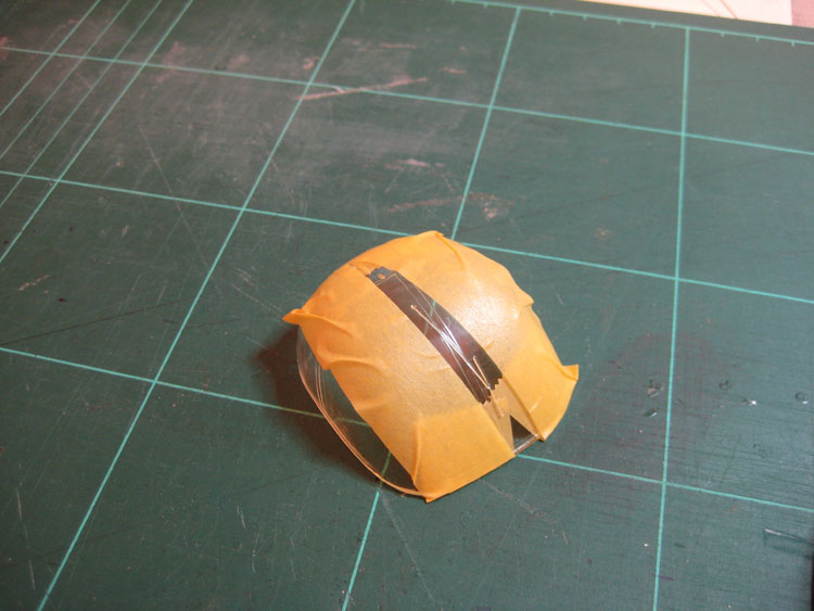
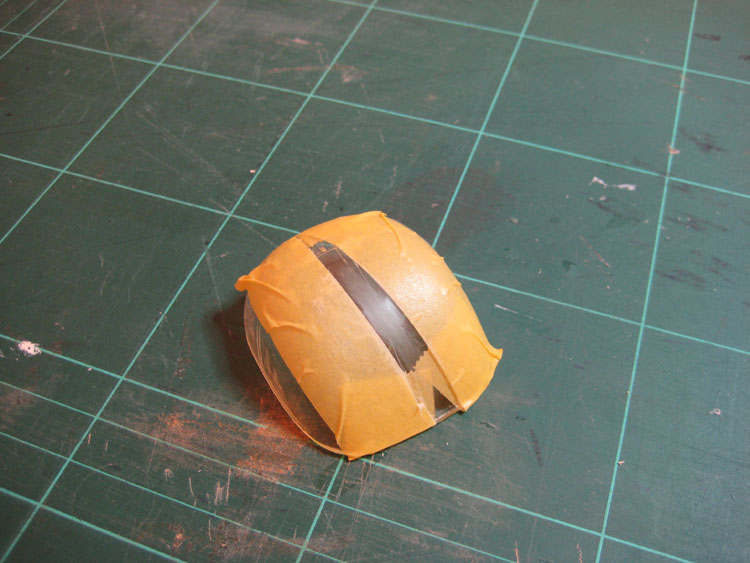
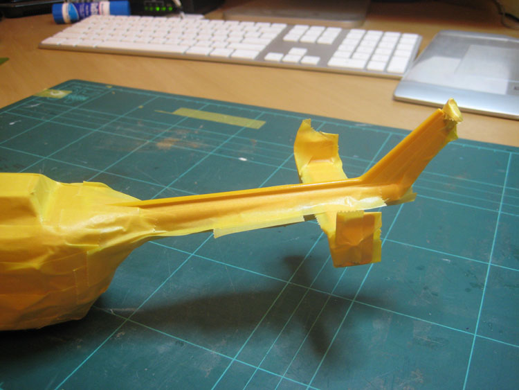
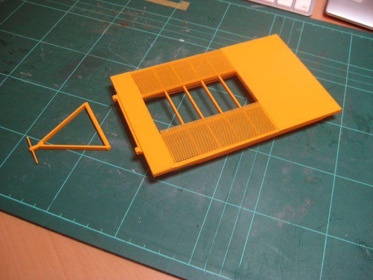
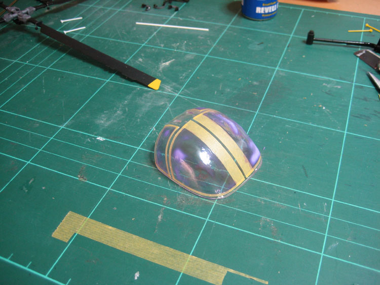
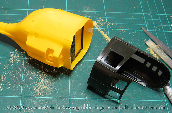
I ran masking tape next to the line to act as a cutting guide and to protect the bits I was going to keep. And I cut ...

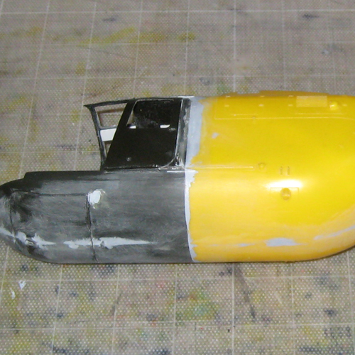
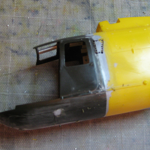
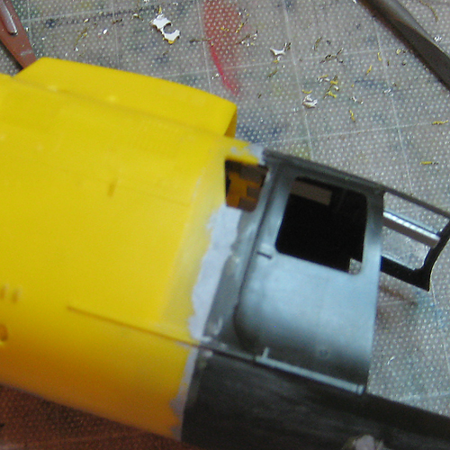
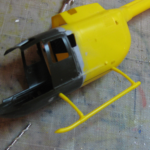
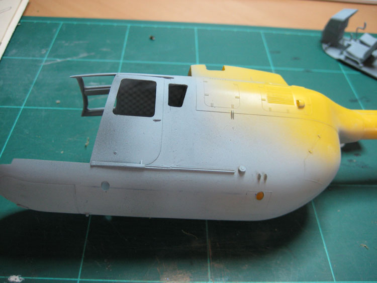
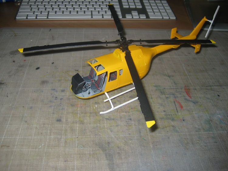
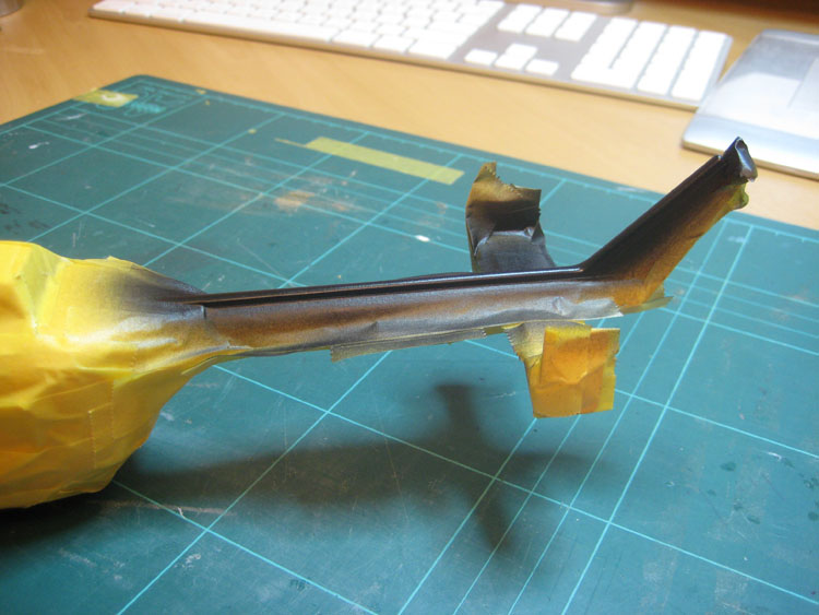
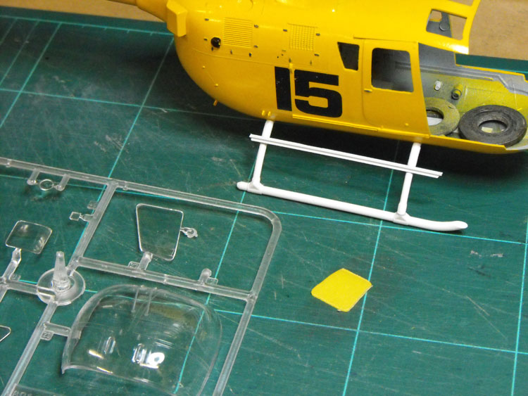
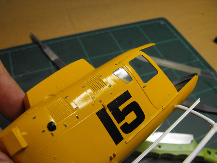
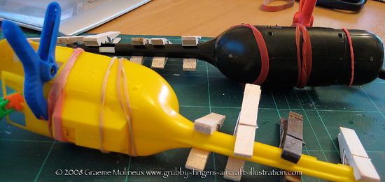
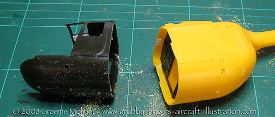
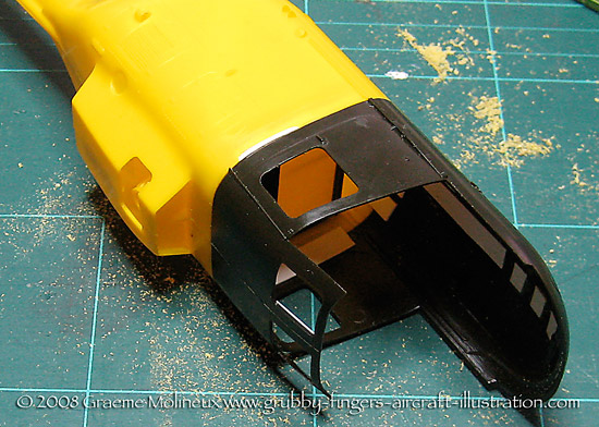
Once the cutting was finished I started breathing again. You can see the overlap between the fuselage sections. The green fuselage was cut immediately in front of the engine nacelle, and the yellow was cut 8mm forward of that line.


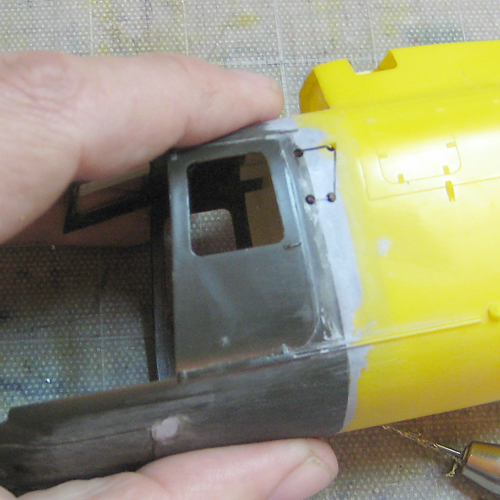
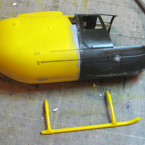
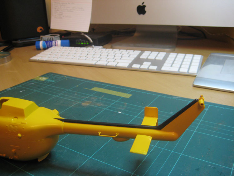
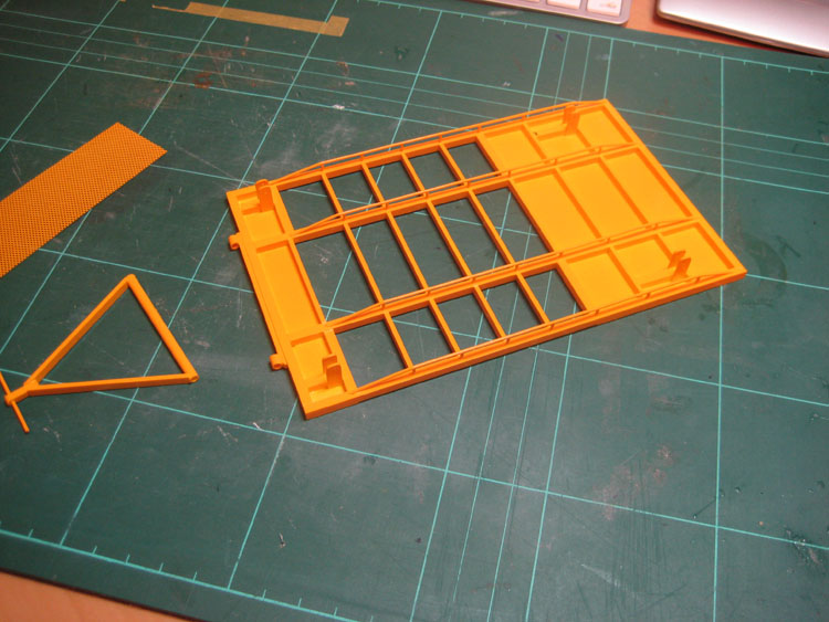
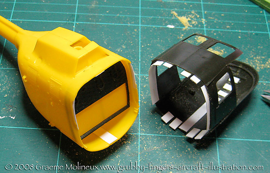
Now the front and rear sections are brought together and glued. I added some thin plastic strip to strengthen the join and cover the hole from what was left of the door window on the yellow section. I also sanded down what was left of the main side doors on the rear section as it was raised.


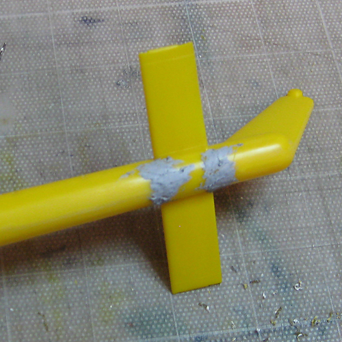
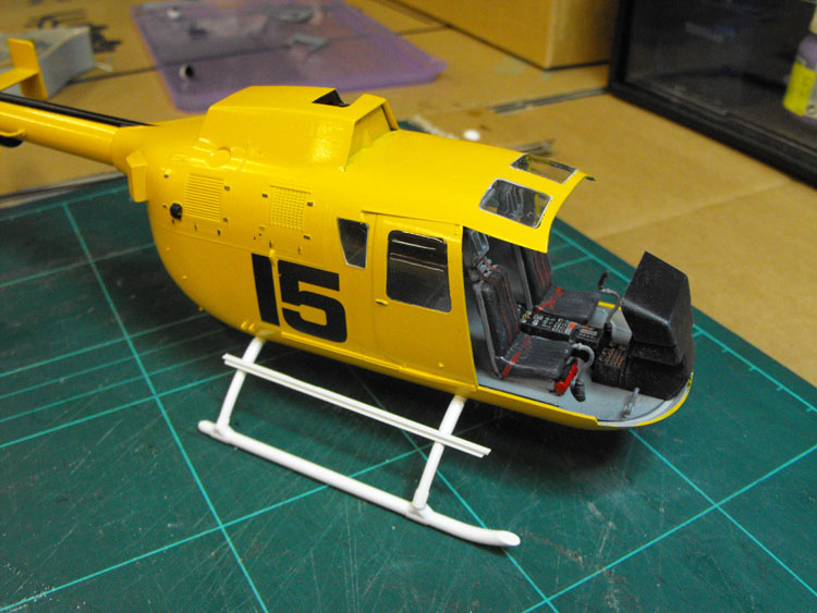
Next steps will be bogging up the join, attaching the tailplane and cleaning it all up. I'll probably start on the interior in the mean time too.
empeter
_VISITCOMMUNITY
Texas, United States
Joined: November 27, 2005
KitMaker: 10 posts
AeroScale: 7 posts
Posted: Monday, March 17, 2008 - 06:09 PM UTC
I have plans to make a Bo-105 CBS in the future, but I was going to make he same cuts as the actual aircraft. I like your method better. I'm in the middle of an HKP-9 build and will be watching your build closely.
CombatKrieg
_VISITCOMMUNITY
Singapore / 新加坡
Joined: January 19, 2008
KitMaker: 517 posts
AeroScale: 62 posts
Posted: Thursday, April 10, 2008 - 10:53 PM UTC
Nice! How's things so far?
Removed by original poster on 09/09/08 - 05:03:10 (GMT).
grubbyfingers
_VISITCOMMUNITY
Victoria, Australia
Joined: September 07, 2007
KitMaker: 404 posts
AeroScale: 339 posts
Posted: Monday, September 08, 2008 - 06:13 PM UTC
Hi Guys!

I've picked up the BO105 again ...

When I left off, I had cut and shut the fuselage. Overall I am quite happy with how that went. Nothing ventured, nothing gained!

A suitable amount of Tamiya putty was then added to the join and sanded back smooth.


The main visual cue to telling the CBS from the standard length CB or the PAH is the extra window at the rear of the cabin. By enlarging a set of plans to the right scale I was able to create a template that was stuck on the side of the fuselage in the correct position.


The window position was then traced off and the corners drilled out ...


... and the spaces between drilled out too.

[

A scalpel was then used to carefully cut between the holes ...


... and the resulting hole filed smooth with jewellers' files.


This was done for both sides.

With the fuselage being longer, the forward hole for the landing skid cross member was in the wrong place. The original forward hole was filled and sanded, and the position for the second hole was marked up.


This was then drilled out, paying close attention to getting the front and rear holes at the same angle and in the same horizontal plane so the model would sit flat on its skids.


The horizontal stabiliser is next to go on. If you are using any of the PAH anti-tank kits for this conversion, you will need to shorten the horizontal stabilisers. The ones from the ADAC rescue set measure 61mm in total span, while the PAH ones measure 77mm. On the PAH stabs there is a prominent panel line where the real extension took place, so you could use this as a guide.


Once attached, the join can be cleaned up.

On to the interior. The floor needs to be extended to match the stretched fuselage. This can be done with plastic card.


A flat rear part-bulkhead is needed for the chopper depicted, as well as a rear troop seat and back pads. These were fashioned from plastic card and rod.


These fit together at the aft end of the extended floor.

The kit ceiling has no detail included so a false ceiling was made from plastic card and a quilted liner was cut from a piece of biscuit packaging.


The kit seats come with a hollow back. These were covered with a piece of card so they looked a bit less kit-like. A dry fit of the components so far looks like this:


To busy up the interior a bit more the kit headrests were added to the seats, a fire extinguisher scrounged from another kit and some ‘cans’ scratched up from hollow rod and thin metal. The ADAC 105 kit includes two nice helmets as well, commendably thin. They should clean up nicely. They don’t come in the PAH kit. Some inflatable liferafts were made from celuclay and sited under the troop seat in the rear too.


grubbyfingers
_VISITCOMMUNITY
Victoria, Australia
Joined: September 07, 2007
KitMaker: 404 posts
AeroScale: 339 posts
Posted: Monday, September 08, 2008 - 06:17 PM UTC
There's a lesson here, too _ Go back to using the camera tripod, Graeme!!
HeavyArty
_VISITCOMMUNITY
Florida, United States
Joined: May 16, 2002
KitMaker: 17,694 posts
AeroScale: 1,728 posts
Posted: Wednesday, September 10, 2008 - 12:09 AM UTC
Hi Graeme, she's looking good. Keep up the good work and keep us posted.
grubbyfingers
_VISITCOMMUNITY
Victoria, Australia
Joined: September 07, 2007
KitMaker: 404 posts
AeroScale: 339 posts
Posted: Saturday, January 03, 2009 - 04:42 PM UTC

There were some sink marks and locating pin holes that needed filling on the underside of the rotor blades. These were filled and sanded and the kit rotor actuators were replaced with rod and tube.


The interior was given a coat of grey.


The outside of the body got some primer to see how the join was going. More filling and sanding needed!


The rotors needed some anti-vibration counterweights added. These were made from bent steel wire and jewellry beads from my daughter’s beading set. A sleeve from wire insulation was cut to length to act as the mounting bracket.


The whole main rotor assembly was then sprayed matt black and, when dry, the tips masked off and sprayed yellow.


Another voyage into new territory for me: Altering transparencies. The kit molded wipers aren’t correct for the chopper I am modelling, so they have to come off and be replaced with scratched items.


The surrounding glazing was masked off to help prevent damage


And then the offending wiper was carefully sanded off. More on this later.


The chopper I am doing has a side-mounted rescue winch. This wasn’t included in any of three donor kits so it was scratched out of tube and card. I drew up some plans based on photos and MBB documentation.


The fuselage, with the join as good as I was going to get it, was then given a matt white primer coat in preparation for the bright yellow to come.


Once the top coat of Tamiya Camel Yellow was done, using a spray pack, it was assembled for a dry run. You can see the interior has been painted and the instrument panel decals applied. The seat harnesses are Tamiya tape.


A step has been added to the undercarriage out of H-section stock.


You can see in this shot the mounting hardware for the rescue winch added above the rear skid tube.


The boom was masked off for a black stripe.


One of my reference pics shows this chopper sitting on a trolley on rails. I thought this might be an effective way of displaying it, and a nice simple scratching job for me. Using the photo as reference and estimating the size, I drew up some plans.


I made up the external frame with 3.2mm square section stock and a metal set square.


The two long members were then cut to length and fitted within the external frame. The small cross members were cut from 3.2 x 1.5 mm stock and carefully sanded to the right length and fitted, using the scaled drawing as a template.


Two top plates were cut to size and glued in place.Here they are being weighted down to keep everything nice and flat and in contact while the glue cures.


There are a series of strengthening rails running along the underside of the main rails. Holes were drilled at each intersection for the support rods and long rods glued into each hole.


These were all cut to the same length by placing a length of the 3 x 3 mm stock along them and cutting off all the protruding ends. The lower rails were then cut to length, bent, and glued in place.


See you soon!

Grubby.
blkhwkmech
_VISITCOMMUNITY
Florida, United States
Joined: August 23, 2005
KitMaker: 90 posts
AeroScale: 12 posts
Posted: Saturday, January 03, 2009 - 05:34 PM UTC
Looking good Cant wait to get home so I can convert a EC-145 in to the UH-72
grubbyfingers
_VISITCOMMUNITY
Victoria, Australia
Joined: September 07, 2007
KitMaker: 404 posts
AeroScale: 339 posts
Posted: Saturday, January 03, 2009 - 05:53 PM UTC
Hi Chris, Thanks.

Stevie B has done the UH-72 from the Revell kit for a campaign last year. His build starts here:

UH-72 build

Maybe this will help?

Grubby.
TedMamere
_VISITCOMMUNITY
Moselle, France
Joined: May 15, 2005
KitMaker: 5,653 posts
AeroScale: 4,347 posts
Posted: Saturday, January 03, 2009 - 06:18 PM UTC
Hi Graeme,

Great work so far!

I hope we won't have to wait four months for the next update. I also hope you will submit this build for a feature...

I can't wait to see the next step!

Jean-Luc
grubbyfingers
_VISITCOMMUNITY
Victoria, Australia
Joined: September 07, 2007
KitMaker: 404 posts
AeroScale: 339 posts
Posted: Saturday, January 03, 2009 - 06:43 PM UTC
Hi Jean Luc.

Thanks.

I'm itching to get this baby finished now so I think t will be done over the next couple of weeks.

I'll consider it for a feature. I haven't explored that so I will have to check it out.

Grubby.
HeavyArty
_VISITCOMMUNITY
Florida, United States
Joined: May 16, 2002
KitMaker: 17,694 posts
AeroScale: 1,728 posts
Posted: Saturday, January 03, 2009 - 07:09 PM UTC
Looking good Greame. The trolley will be an interresting base. Keep up the good work.
grubbyfingers
_VISITCOMMUNITY
Victoria, Australia
Joined: September 07, 2007
KitMaker: 404 posts
AeroScale: 339 posts
Posted: Monday, January 12, 2009 - 06:28 PM UTC

The result of this, once sprayed up, looks like this:


Meanwhile, the windscreen has been sanded with varying grades of wet and dry to this appearance:


It was then attacked with a nail-buffing kit to get this result:


And then a coat of floor polish to shine it up again...


..which is about as good as ths one is going to get! Overall, I’m pleased with the result, considering it’s the firsttime i’ve even tried this. Next time I’ll keep the damaged area and resultant sanding to a bare minimum.

The canopy was then masked up with Tamiya tape cut into itty bitty strips and the space between filled with Maskol.


A coat of paint...


... and viola!


I also rustled up a base graphic in Photoshop. I’m not sure yet how I’ll use it, possibly layer it with cardboard and put some metal rails in to give it some relief.

grubbyfingers
_VISITCOMMUNITY
Victoria, Australia
Joined: September 07, 2007
KitMaker: 404 posts
AeroScale: 339 posts
Posted: Friday, June 12, 2009 - 11:23 PM UTC
And you thought I’d disappeared off the face of the Earth! I was certainly wrong about the couple of weeks, but I’m underway again. Here’s the next installment.

On to the rest of the glasswork. The new side windows were shaped out of spare side windows from the second donor kit. I ran tape over these to prevent scarring while they were cut and sanded to fit. I glued the legs on at this stage too so I didn’t have to keep finding a valley to sit the fuselage in. Note the extra passenger step rail added from H-section strip.


I then fitted them using a little PVA glue.


The other side windows were then trimmed to fit and glued with PVA, as were the roof windows. The interior was then glued in lace and the whole lot set aside to cure.

Avus
_VISITCOMMUNITY
Roma, Italy
Joined: March 10, 2006
KitMaker: 302 posts
AeroScale: 112 posts
Posted: Saturday, June 13, 2009 - 05:56 AM UTC
How'd I miss this thread?!
Astonishing work Graeme!
grubbyfingers
_VISITCOMMUNITY
Victoria, Australia
Joined: September 07, 2007
KitMaker: 404 posts
AeroScale: 339 posts
Posted: Saturday, June 13, 2009 - 06:13 PM UTC
Thanks, Klaus.

You probably missed it as the model has been languishing for 6 months in a box!

But now it is bathing in the light of day once more.

Graeme.
grubbyfingers
_VISITCOMMUNITY
Victoria, Australia
Joined: September 07, 2007
KitMaker: 404 posts
AeroScale: 339 posts
Posted: Sunday, June 21, 2009 - 02:40 PM UTC
Next installment:

I next scratched up some basic wipers. The arms were made from electrical wiring with the insulation removed from both ends. This left a short wire at one end to bend and poke into a hole in the windshield, and a longer exposed end to represent the tapered wiper arm. I cut two short sections of aerofoil section Plastruct to act as the wiper blades.


These were then painted in black and added to two holes drilled in the windshield with PVA glue.


I then turned to the display base. I had found an octagonal solitaire board with no pieces at an Op shop and thought it might make a nice base. I printed out the concrete base I showed you earlier and glued it to some nice solid cardboard. I wanted to have the trolley actually sitting on rails, so I got hold of some HO scale rail line and cut it to length, chamfering the ends so it matched the edges of the display base. I cut the cardboard base so it would sit either side of the rails and give a nice realistic sunken effect to the rails themselves.


The windshield was then glued in place, again using PVA glue, followed by the cockpit doors. I was intending to leave the cockpit doors open to show some of the interior detail, but it spoiled the look of the helo so much, I glued them shut! You can still see most of the detail through the clear transparencies anyway.

The rescue hoist, after being painted gloss black, was attached with superglue. Then attached again after I dropped the model!


Avus
_VISITCOMMUNITY
Roma, Italy
Joined: March 10, 2006
KitMaker: 302 posts
AeroScale: 112 posts
Posted: Sunday, June 21, 2009 - 07:27 PM UTC
You keep proceeding splendidly and the base looks promising, too.
Keep us updated!
DougCohen
_VISITCOMMUNITY
Texas, United States
Joined: May 27, 2009
KitMaker: 1,293 posts
AeroScale: 1,072 posts
Posted: Monday, June 22, 2009 - 05:17 AM UTC
Very cool man I love it cant wait to see it done.
grubbyfingers
_VISITCOMMUNITY
Victoria, Australia
Joined: September 07, 2007
KitMaker: 404 posts
AeroScale: 339 posts
Posted: Saturday, June 27, 2009 - 09:10 PM UTC
After glueing on the tail rotor, stinger and a couple of other bits and pieces and assembling the base, this build draws to a close! Here are some pics of the finished helo.


See you next time!


Grubby.
thehannaman
_VISITCOMMUNITY
New York, United States
Joined: April 04, 2006
KitMaker: 279 posts
AeroScale: 194 posts
Posted: Sunday, June 28, 2009 - 02:12 AM UTC
Awesome work Graeme! I'm not much of a rotor-head, but I certainly have to tip my hat at such nice craftsmanship. That is one good looking model!
Avus
_VISITCOMMUNITY
Roma, Italy
Joined: March 10, 2006
KitMaker: 302 posts
AeroScale: 112 posts
Posted: Sunday, June 28, 2009 - 09:05 PM UTC
You must be kidding!
What a neat and clean workspace!

Oh, outstanding helicopter, by the way!
grubbyfingers
_VISITCOMMUNITY
Victoria, Australia
Joined: September 07, 2007
KitMaker: 404 posts
AeroScale: 339 posts
Posted: Sunday, June 28, 2009 - 11:44 PM UTC
Ah yes, you mean the cardboard print of a clean workspace that I shoot all my photos on!
thegirl
_VISITCOMMUNITY
Alberta, Canada
Joined: January 19, 2008
KitMaker: 6,743 posts
AeroScale: 6,151 posts
Posted: Tuesday, June 30, 2009 - 01:42 AM UTC
Very nice clean build and love that yellow !

Excellent job .
 _GOTOTOP