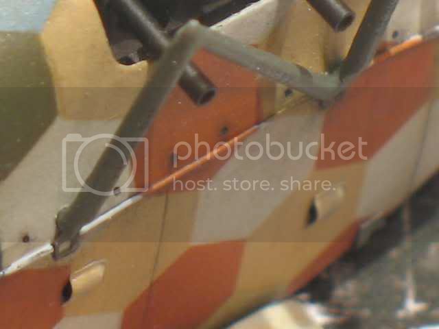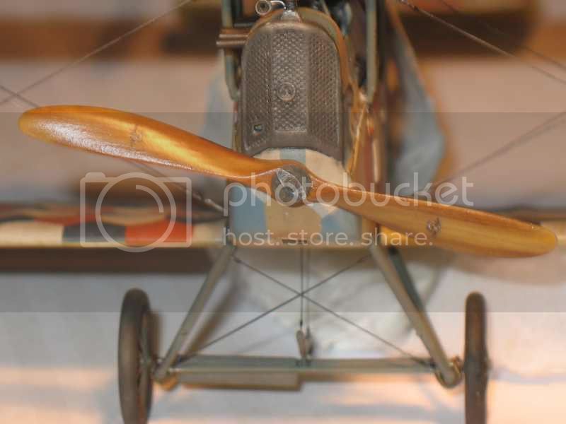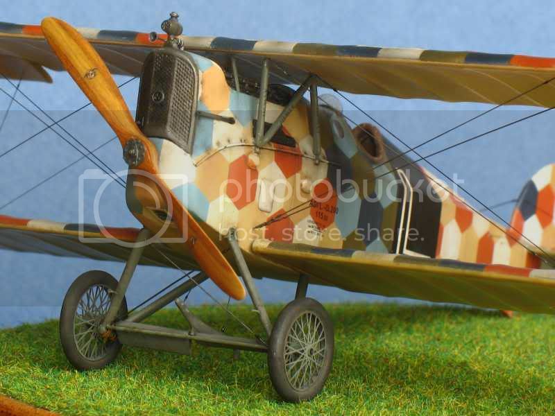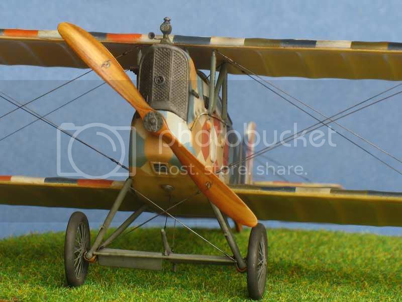


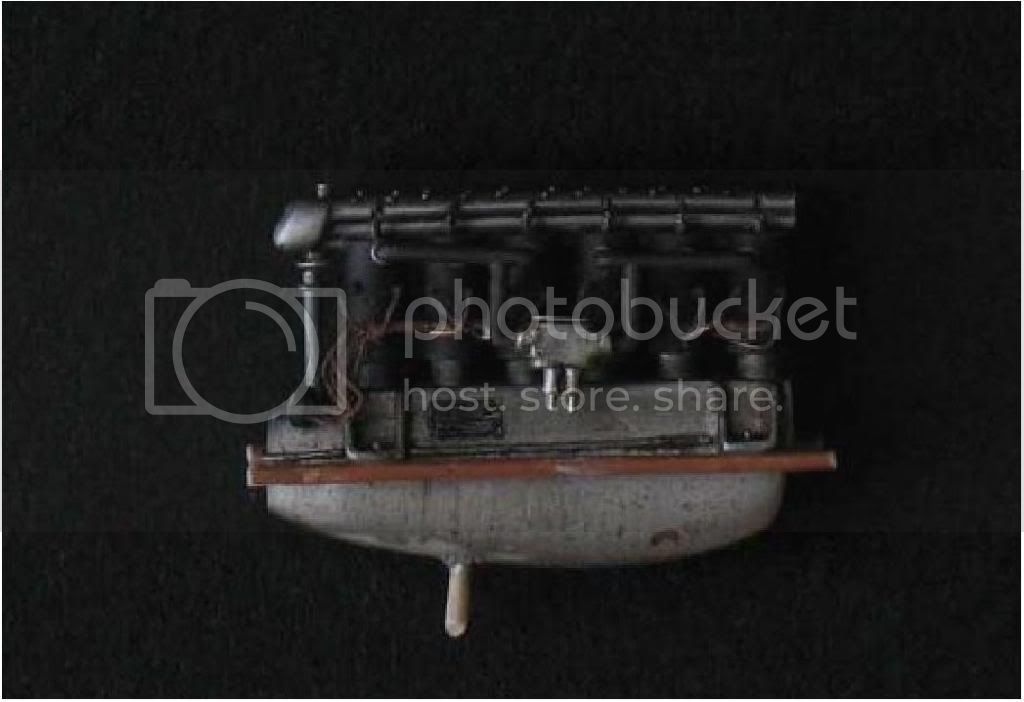
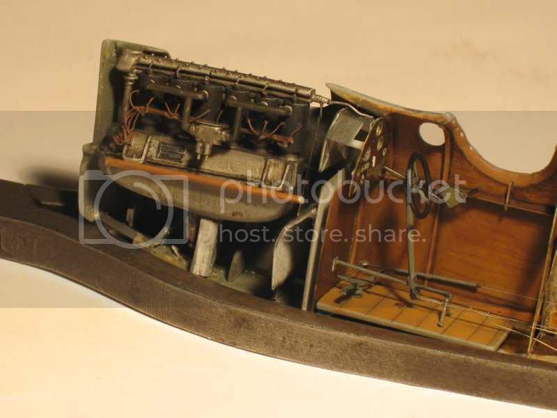
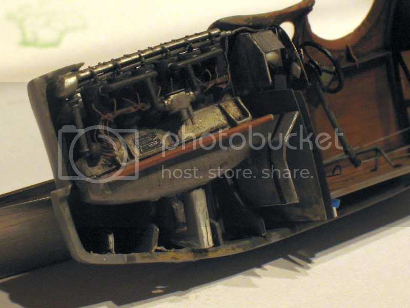
The engine:

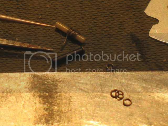
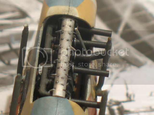
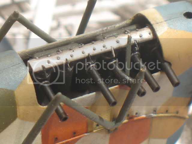
I kept the engine block (the big aluminum thing) and remade the cylinders that were neither identical nor right. The springs are made with a copper wire wound. The top engine is a plastic rod-shaped half-cylinder cut and drilled to put the nuts (wire lead). All painted aluminum, painted black "smoke" from tamiya.
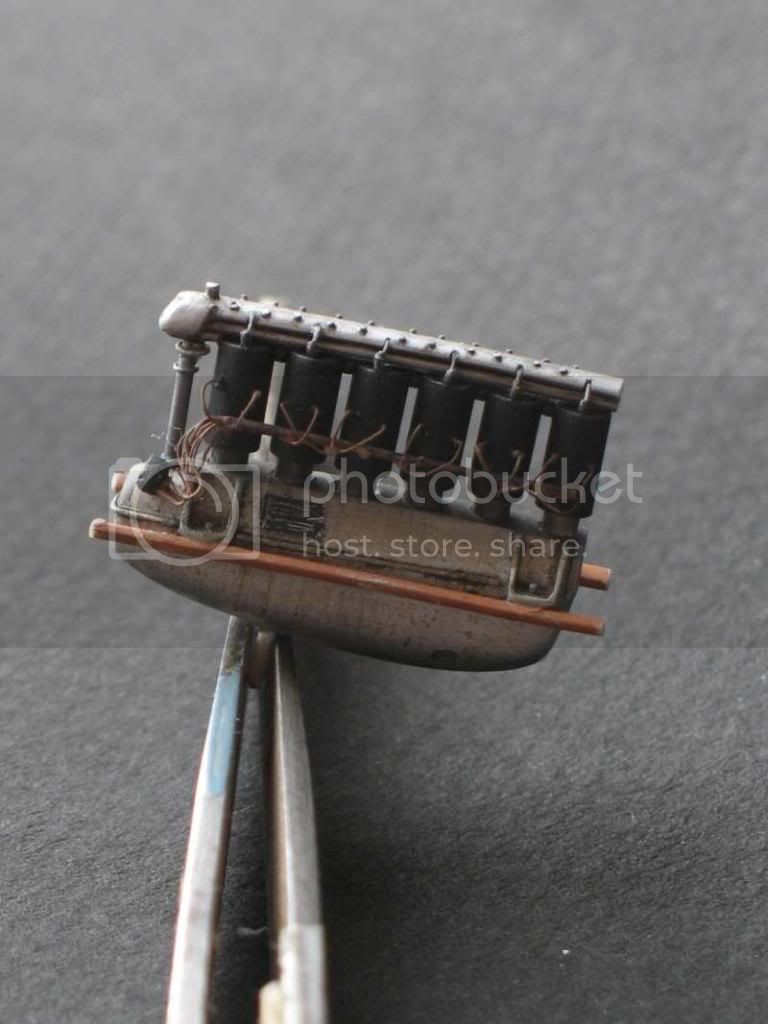

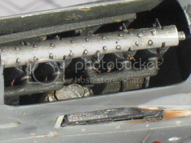
Pipes entering the cylinders are not yet in place because they are not glued. The housing at the base did not fit ... but we will not see it
The "stem" at the very front must be moved because it is skewed and it shows when the engine is in place.
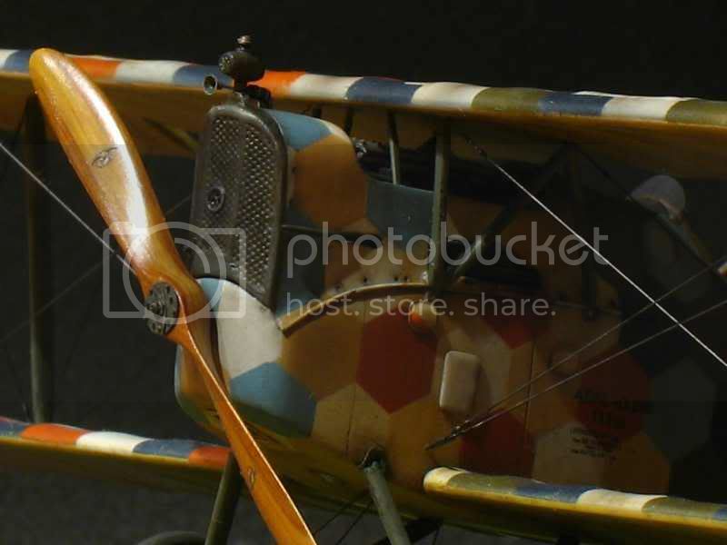
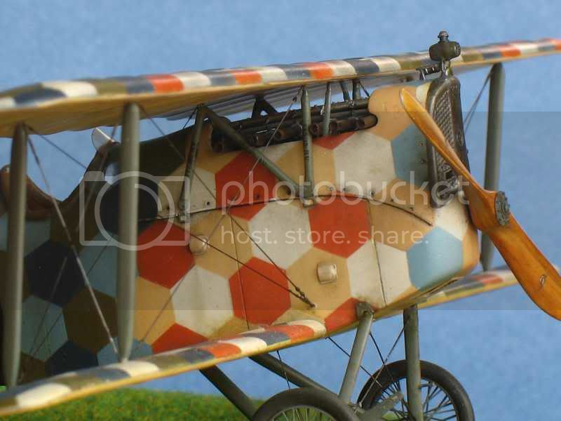
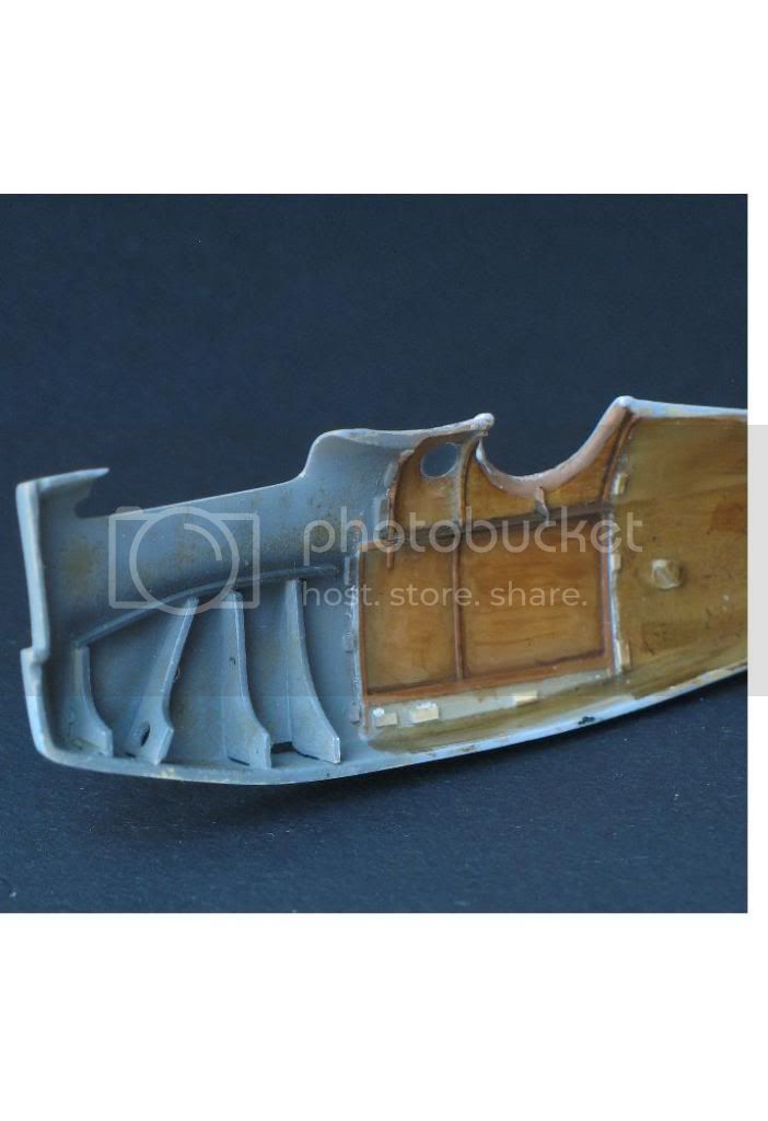
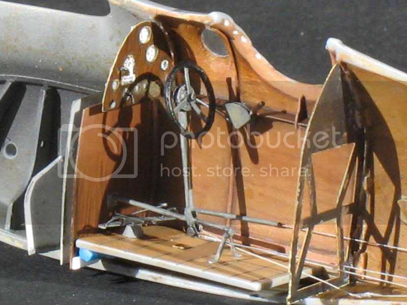
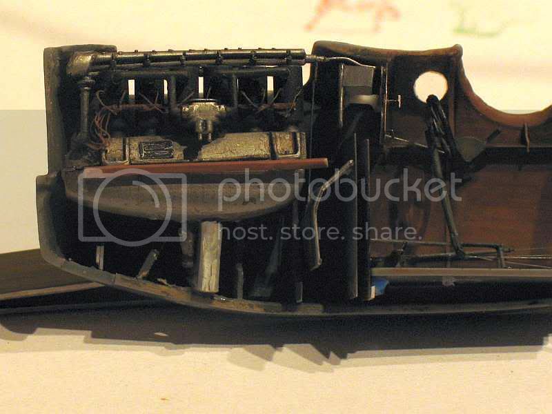
Inside:
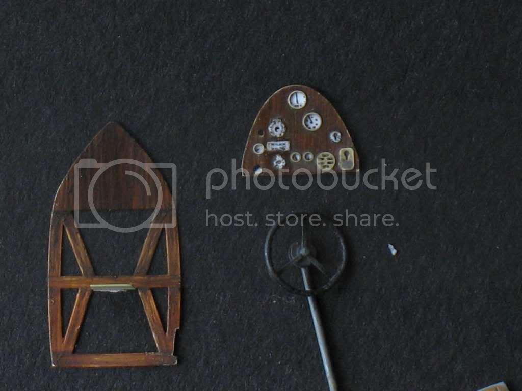
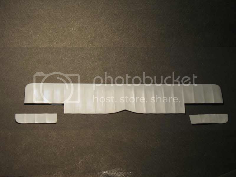
I added edges that go instrument panel to behind the driver's seat on each side of the cockpit.
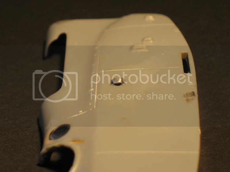
The windows were moved because they are too high on the angle of the fuselage. They are rounded on their upper part (there are normally flat). I have lowered and enlarged for easy paste. then sanding and polishing. Their diameter is too large will be reduced when painting.
The instrument panel is painted with Humbrol paint color light wood with streaks of brown ink hazelnut (Prince August) and then for several coats brown ink. . Then I used sandpaper to expose the "clocks" brass (I think they were gray or aluminum but...) The bottom of the face are black in the original model but on my Photos they are white. So I've redone with black ink.
The pulley is made of coiled copper wire and the pulley is made with two small access doors in photo cutout of a model of Camels.
The engine mounts are made of plastic card but do not see nearly. I had not thought about the exhaust pipes that obstruct the view seriously.
The wood of the interior is painted in the same way that the instrument panel .

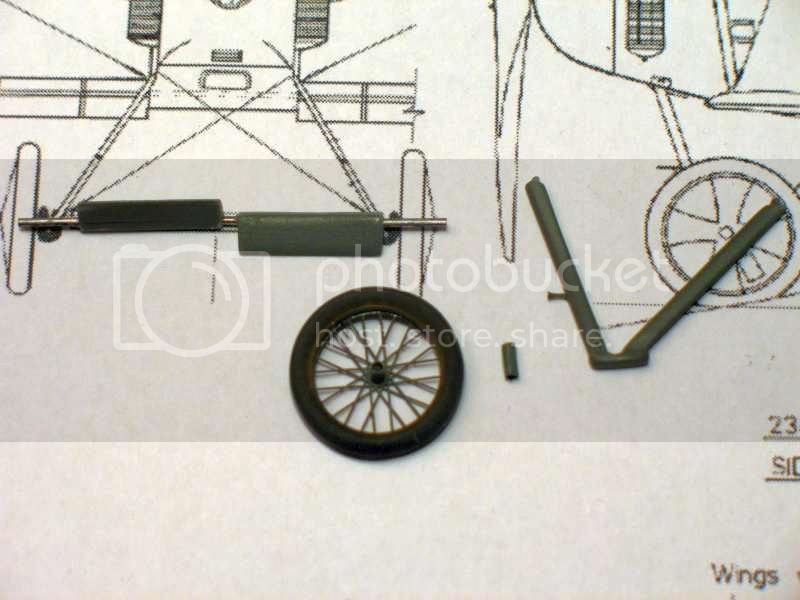
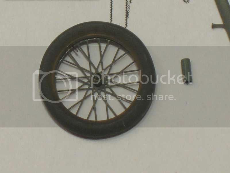
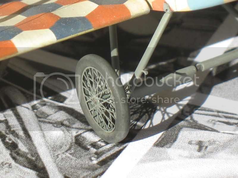
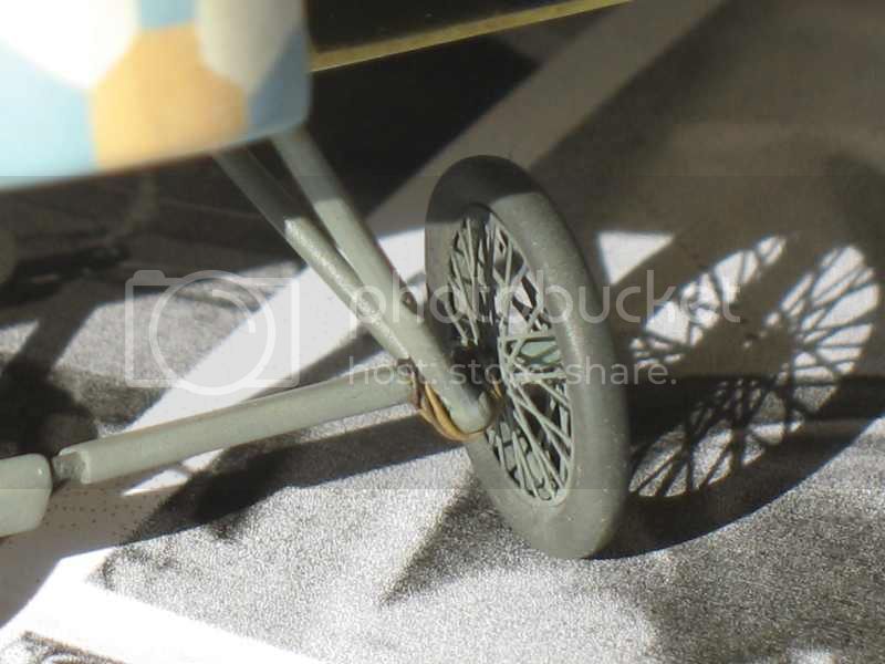
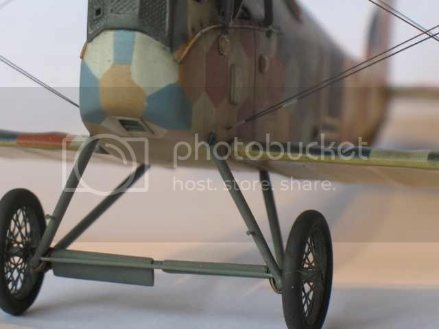
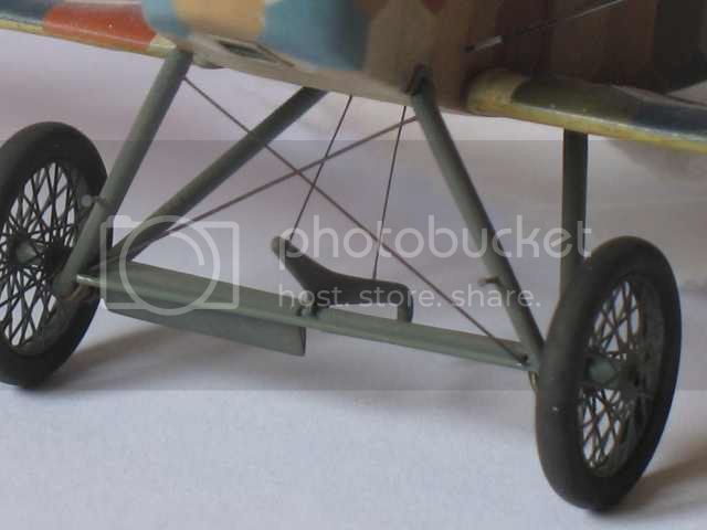
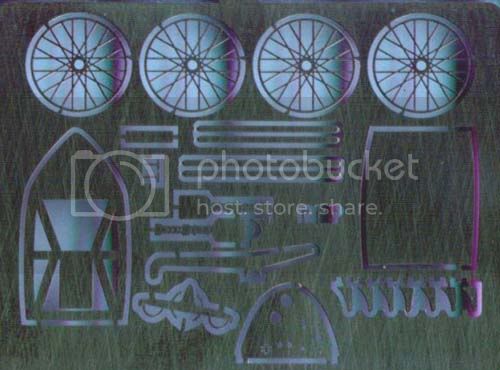
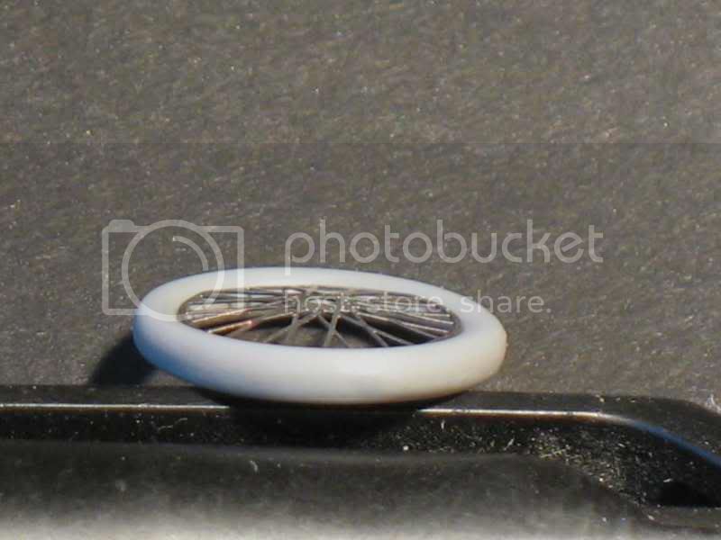
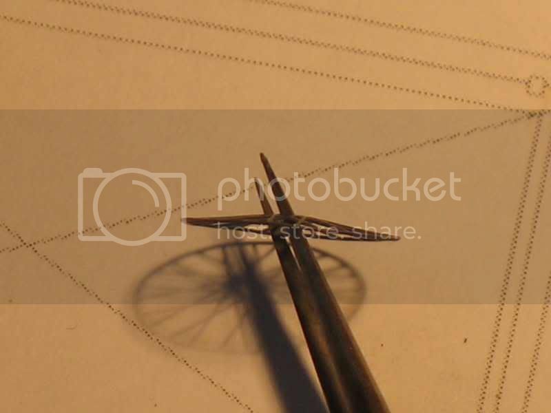
The spokes are mounted on flexible tire included in the kit but the tires are too big! So I emptied the plastic wheels up to enter the spoke. The spoke are rendered "convex" by placing them on a large diameter ball. Dangerous for the spokes and not very useful. I would dissuade you.

The left side panel which hides the gun is opened. I do not have pictures of the opening, just drawings.


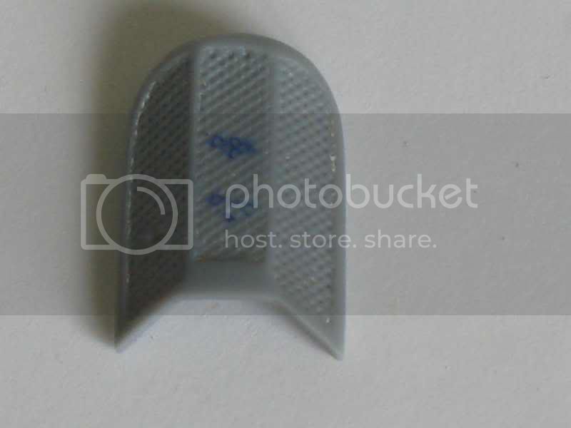
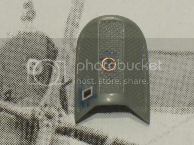
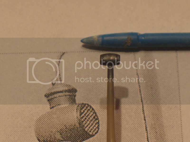
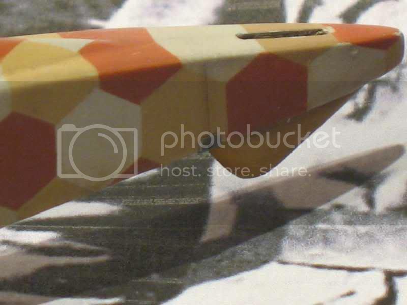
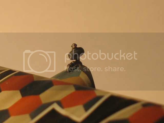
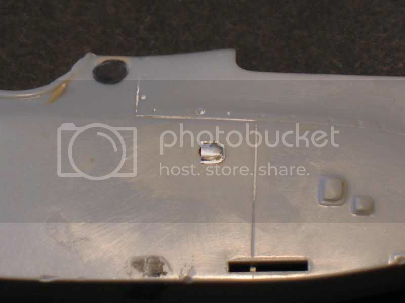
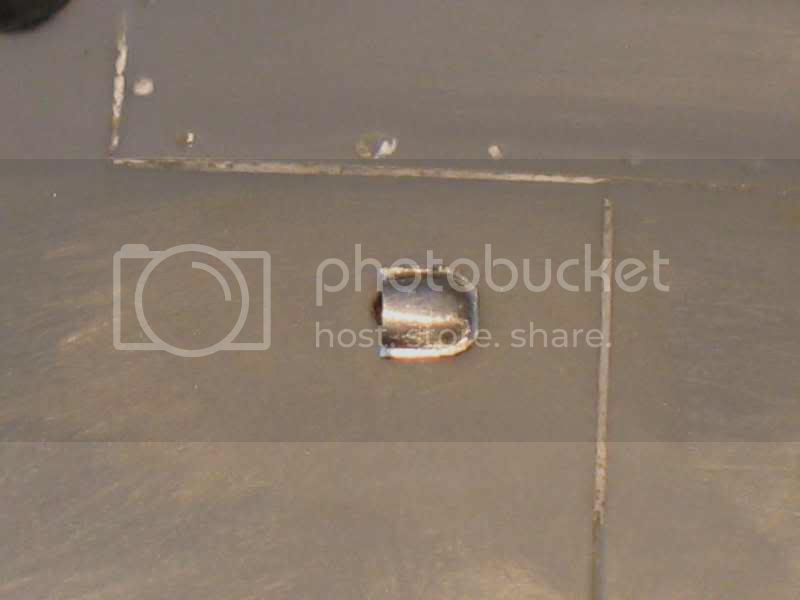
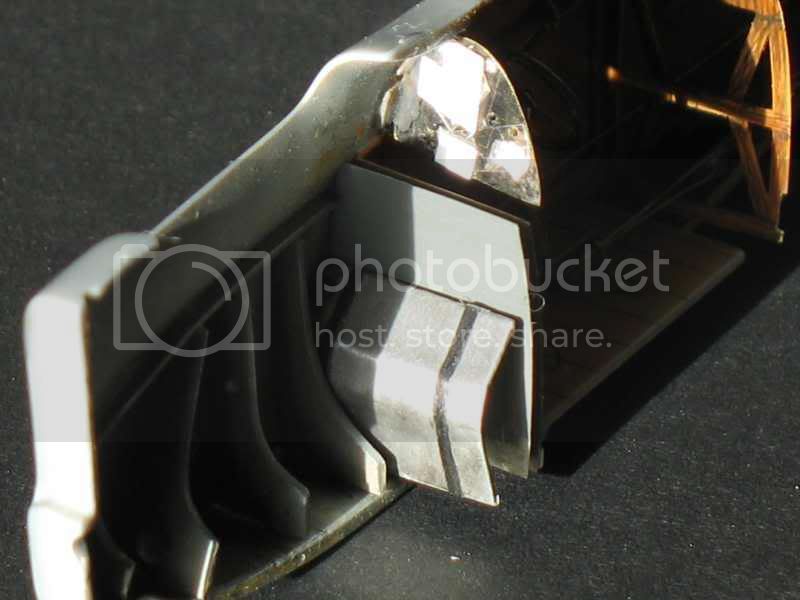
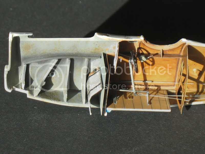
Air intake:
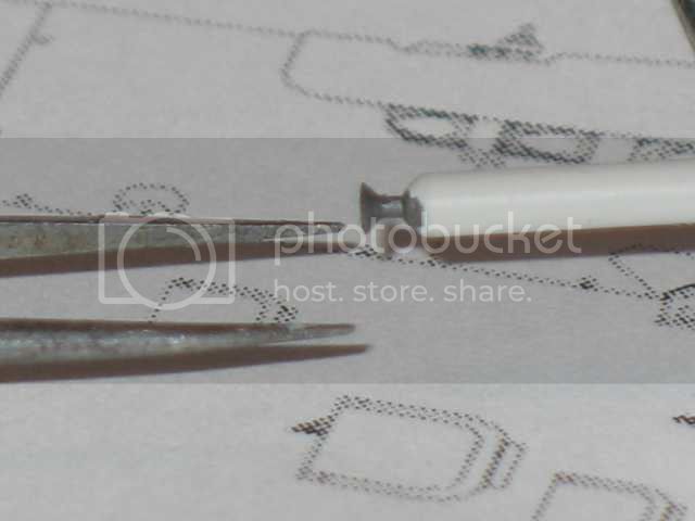
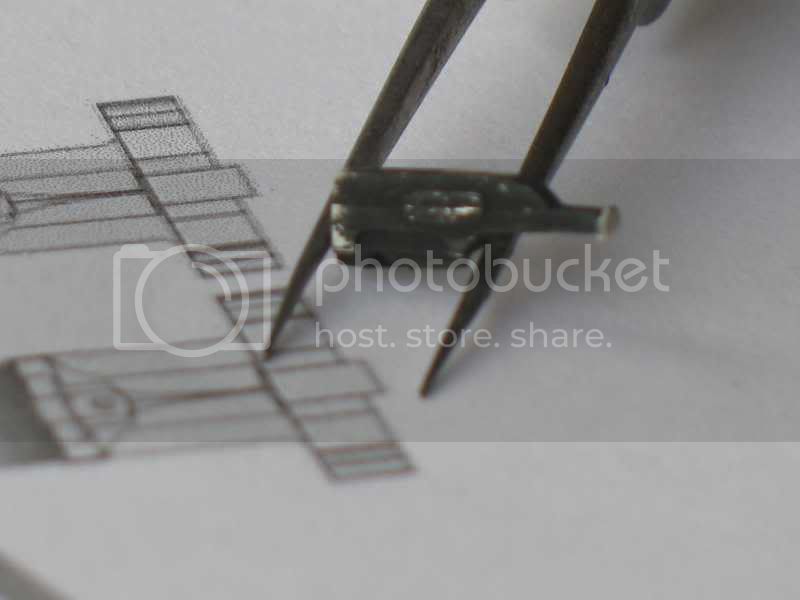
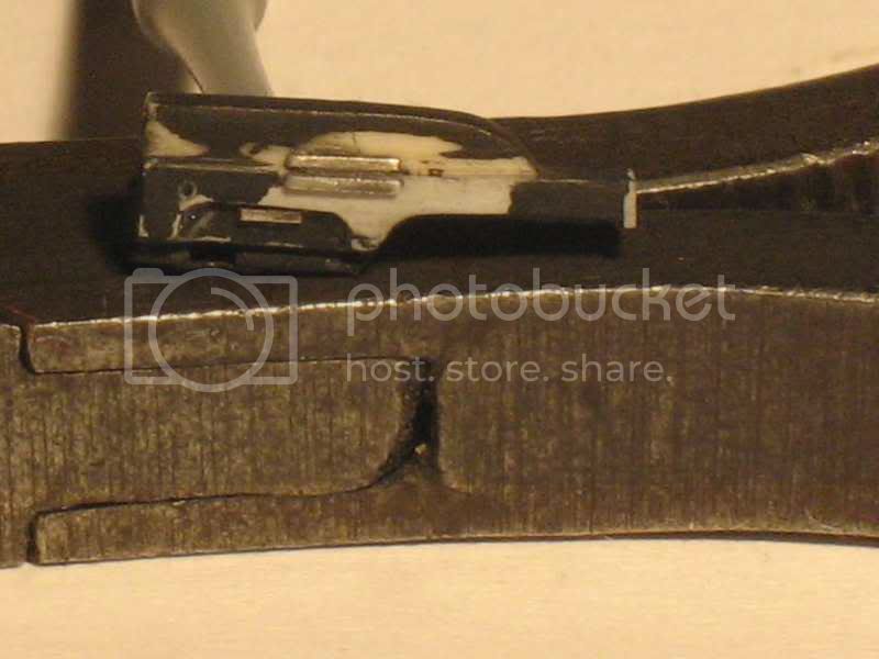
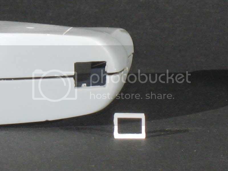
The model (in white) is glued on a support (CD box) and the piece of metal (lead) secured with tape. A good shape is easy to do, not 3 minutes more, but cutting around the air intake give it a shape... You must do two or three others who will accompany him.
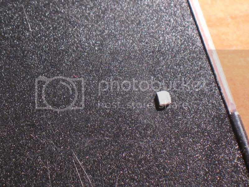
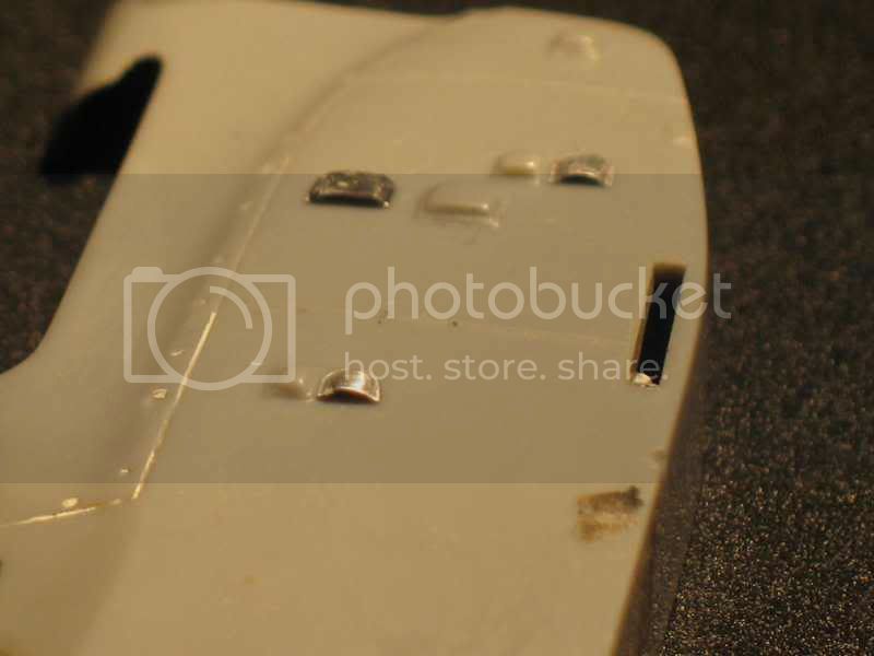
the air intake located furthest forward is to remove the right and left (I think). They are visible in any photos. Neither in the book in Japo (p30 to 32) or in windsockdatafile (p6 bottom photo). the largest is more like an inspection door closed on 4 sides to an air intake"".
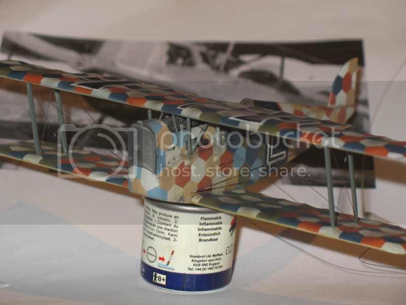
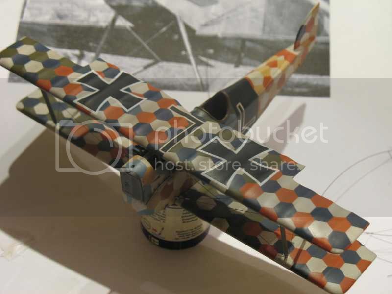
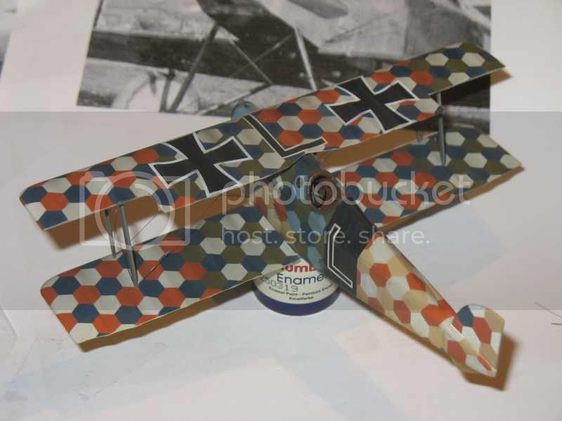
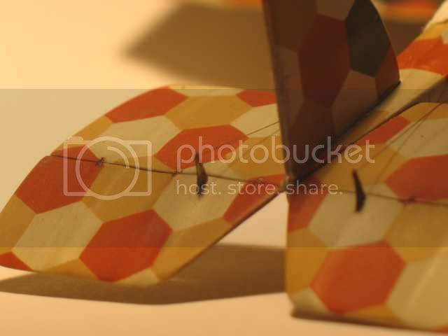
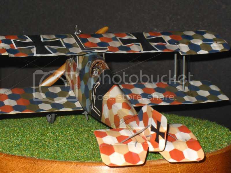
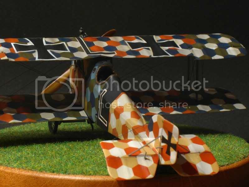
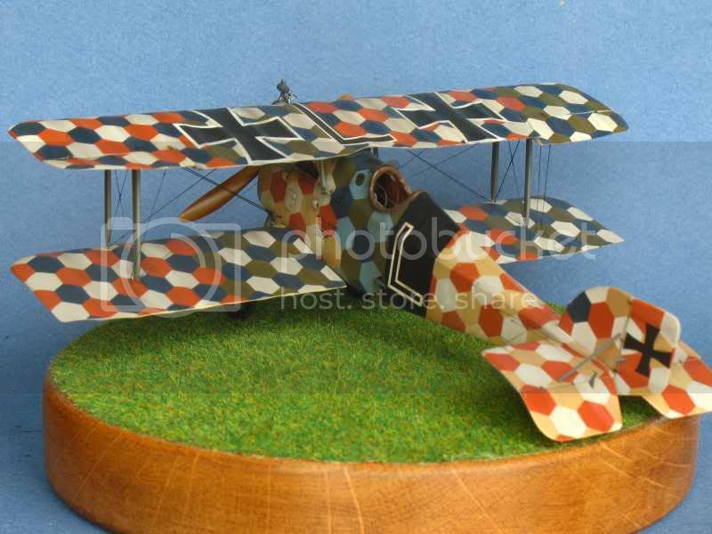
Wings:
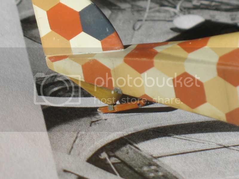
The ailerons were cut and must be "twisted" up into hot water.

Clearly visible in many photos. The flap is removed with a file and frame size of the flap is made. It will then stuck chewed. The "fins" will be glued at the end.
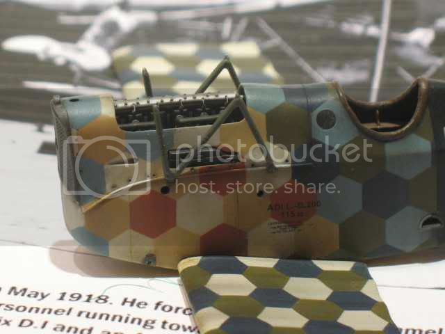
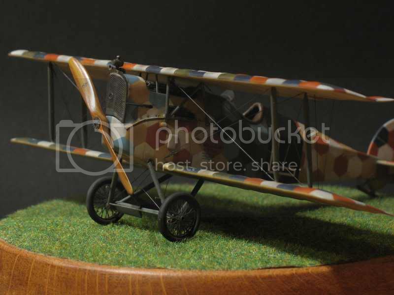
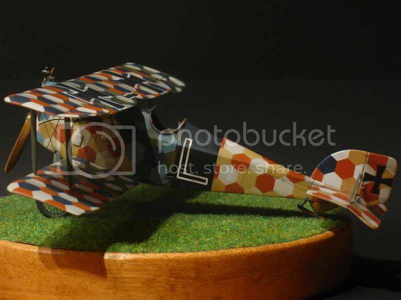
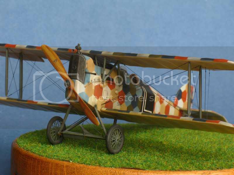
the fuselage:
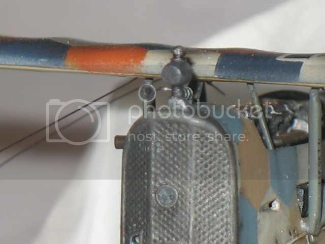
A tank is glued under the engine. It is a plastic card with aluminum tape.
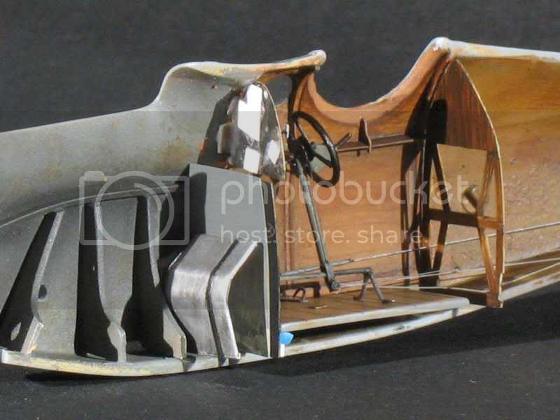
The steering wheel is stuck. I have no other picture of the base of the control column .

The three "frames" in a "U", placed under the engine and placed at the bottom of the fuselage are not visible at all when the engine is in place.
A final layer remains to pass to make everything smooth. dirt and then others.
The fuselage is glued and putty will be useful everywhere.
We see nothing under the hood except the sanding dust and pieces of engine were loose.
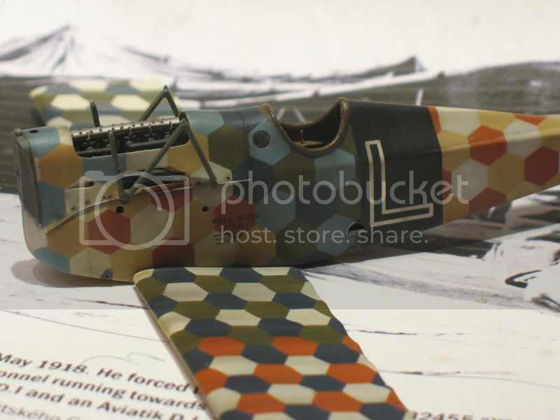
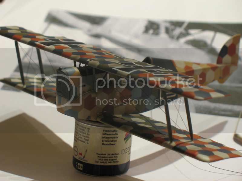
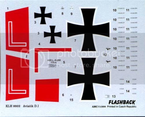
I started to put decals on the wings ......but the ribs are very deep and decals very hard.
The microsol softener arranges things but it's not beautiful.