_GOTOBOTTOM
World War II
Discuss WWII and the era directly before and after the war from 1935-1949.
Hosted by Rowan Baylis
FEATURE
Preview: Eduard's Spitfire IX
Jessie_C
_VISITCOMMUNITY
British Columbia, Canada
Joined: September 03, 2009
KitMaker: 6,965 posts
AeroScale: 6,247 posts
Posted: Monday, February 11, 2013 - 04:08 AM UTC
The big news out of the 2013 Nuremberg Toy Fair was the announcement of a new Spitfire Mk. IX soon to be released by Eduard. Aeroscale''s Jean-Luc Formery attended the fair, and was one of the lucky recipients of some test shots of the new kit. Aeroscale brings you this sneak preview.

Link to Item

If you have comments or questions please post them here.

Thanks!
Antoni
_VISITCOMMUNITY
England - East Midlands, United Kingdom
Joined: June 03, 2006
KitMaker: 574 posts
AeroScale: 573 posts
Posted: Monday, February 11, 2013 - 05:22 AM UTC
From Eduard's January Newsletter:

"Here comes Eduard’s
new Spitfire Mk.IXc. This kit is the best of all we have done up to now, and I dare say, the best of 48 scale kit production anywhere.... period. This is another product of our construction and engineering philosophy, that has in large part been defined by input we have received and analyzed from our 1/48th scale Fw 190s and Bf 110s. The result is a compact model with a very precisely rendered surface, and a reproduction level of the same new standard covering the visible interior details of the cockpit, landing gear and wheel wells.
We are not uncovering the engine or the armament, nor are we treating their respective mountings. For those modelers that do like to go down that road, we are also preparing Brassin sets to enable them to do that. Their use is already taken into consideration in the plastic model and will greatly accommodate their integration with the kit. The Brassin sets
will cover the engine including cowls, armament installations, and a resin cockpit that will include the radio set. The list of PE brass will include the flaps.
But, back to the model. In the interest of keeping this as short as possible, I would compare this kit with our 48th scale Bf 109E. As noted earlier, there will be no engine, and there will be a fine rendering of the rivet patterns that we have shown an ability to do in a very effective and subdued manner. There will be roughly a third more rivets. That’s because if actual fact, the Spitfire had about a third more rivets than the Bf 109E. So, even here, we were careful with the riveting, something that was a tough choice to make with the Spitfire in terms of what to leave in and what to leave out. The so-called rivet counters and makers of riveting tools will have their own opinions, but our goal is to produce a product that will promote the notion that Eduard kits don’t need riveting, nor puttying for that matter. And since we are at puttying, I have read about Spitfires being puttied over to cover the rivets, which should not be visible. I don’t know. It may well be so, but all of the Spitfires we looked at, the rivets were visible.
It’s not going to be as simple a build as all of the above suggests, though. It will include five sprue sets containing a total of 207 parts, 14 of which will be clear. For a compact single-engined fighter, that’s a pretty good number,
and may lead you to think that this will be over-engineered, a la our 1/48 Bf 110.
But it won’t be. There are a lot of parts, but many are optional and so duplicated or even triplicated to allow for those options. This is to allow for as much variation of the type as possible. So, a lot of what you get will be doubled up for use as needed. This will include the tail surfaces, nose section with upper and lower parts, exhausts, carburetor intakes, landing gear legs, their covers, and wheels (specifically tires). Wheel hubs will cover three variations, same as the cannon muzzles. These are hollowed out, same as the exhaust pipes. There will be two types of wingtips and
two types of gunsights. There will also be two types of tailwheels, one as a single unit, and the other with a separate wheel. Probably the most noteworthy variation of parts involves the cockpit doors. This was a curved feature
on the actual aircraft that tended to straighten out on opening. In fact, this is a feature that was not limited to the doors of the Spitfire, but we did make two sets of these doors, one maintaining the consistent fuselage curvature
when closed, and a straighter version for those who will wish to display it in the open position. Keeping just one set was not deemed the way to go, which you will surely understand.
Most will probably go for the open variation, others closed but with an open canopy. Many pilots had a graphic on their doors, such as Smik’s ‘DU-N’, which carried kill marks on the
door, and will be included as a marking option in our kit. A lot of modelers will not want to open the door and obliterate a display of kill marks! And closing this cockpit would be
a sin! There will be two variations of the canopy, one open and one closed. The open canopy version will open the door to the shape purists to complain. It’s a tad wider than the
closed canopy variant, but this is to allow it to fit over the spine in the open position. This is typical for this type of layout, and doesn’t seem to bother too many people. What is
more important is what lies beneath the canopy. This is where things happen! The cockpit is made up of some 38 detail parts. Again, this can come across as somewhat complicated,
but it really isn’t. The parts are accurate, fine in their detail, and fit where they are supposed to. There is no flash, there is no seam to ruin their look, and there are no ejection pin marks where they would be visible. The ejection
pin marks have been a strict no-no in our company from the beginning, and is one of the things that make us unique among manufacturers.
The mold lines have been eliminated for some time now, and there is no need to mention flash. The cockpit is the result of a lot of painstaking work, the best we have produced to date, and is designed to compete even with the best resin sets available. It’s true that the technology used to produce this kit raises the number of parts in the kit, but it should
also be noted that it allows for the increased number of parts. It all also goes together like Lego bricks and the end result is thoroughly convincing. Adding a bit of PE to this cockpit will practically bring it to life. The story is applicable to the landing gear as well. The well is unexpectedly well detailed, even if it is at the expense of segmenting the walls of it into several parts. But we ensured
that all parts sit precisely as they should, resulting in an unsurpassed assembly in 1/48th scale. The same goes for the standard achieved with the landing gear itself, although it
is a fairly conventional affair. It includes the struts, tires, separate hubs, covers and, in newer versions, oleo scissors that all come together in a sub assembly that is far from boring! Details abound in this Spitfire kit. On the exhausts, the propeller, bomb racks, the bombs themselves, on the control surfaces.... everywhere. We have gone into unexpected and unprecedented territory in detail.
For example, the machine gun muzzles are visible in the openings in the wings. These were often covered with tape for aerodynamic reasons on the real thing, and we have managed
to simulate this as well. The tape would tighten over the opening to become concave. It’s a small but awesome detail, and care must be taken to not ruin it during assembly. I think
I’ll stop here. To sum up, the Eduard Spitfire is so far the most extensively thought out kit we have ever produced. Way back when it was going to be a 1/32nd scale project, we
intently studied several accessible Spitfires. The founding piece of reference that we used for this project was the book by Paul Montfort,in which he created a very significant study
of the subject. We added a bit to it, and we studied and verified the drawings diligently. The few small details that were missing we added. All in all, the amount of work expended
on one project has been immense, but the end result will certainly speak for itself! But, what about camouflage schemes? MH712, WX-D of No. 302 (Polish) Squadron, MJ296,
DU-N of No. 312 (Czechoslovak) Squadron flown by Otto Smik, MJ586, LO-D of No. 602 Squadron flown by Pierre Clostermann, the silver MJ250 UF-O from Italy, and ML135 YO-D flown by J. Billing of No. 401 Squadron. Hopefully this is a mix that will satisfy pretty much everyone. Those who would like to model different Spits will need to source them elsewhere, of which there is absolutely no shortage, or they can wait for our two special editions. More on them a bit later. April will also see the availability of the Overtrees concept for these as well. These will atypically be available until September.
The reason are the two special edition kits. The month will be so dominated by the Spitfire kit that there hardly seems to be any reason to complicate things with a LIMITED EDITION
kit. So we’ll tone it down with a WEEKEND kit of the F6F-3 Hellcat in 1/48th scale, which is another re-edition of a sold out kit.

On August 13, we will be celebrating the anniversary of the return of our pilots from England after the end of the Second World War. We would like to commemorate this milestone with the release of a kit exclusively dedicated to the event in the
form of a Spitfire Mk. IX of the Czechoslovak Air Force. It will emulate the Royal Class idea, in that it will contain two complete kits and will cover the use of the Spit by the Czechs and Slovaks during World War Two and after in
Czechoslovakia. It will contain the usual photoetched brass and Brassin parts. The defining part of this specific release will be in the decal options. It will include a wide assortment of Spitfire Mk.IXs flown by Czechoslovak pilots in
the war and after. How many Spitfires will be represented, or if the options will include users that these were eventually passed on to, is not at the moment certain.
Similarly, it has not yet been definitively determined the method of delivering these kits, and we are discussing this with the Czech postal service. Ideally, we would like the service to deliver these exactly on August 13th, at least within their jurisdiction of the Czech Republic. But because the bonus in this edition of the kit will be an exclusive postal stamp issue with an anniversary envelope (?), it would
even be nice for these to be postmarked on the 13th as an alternative. The packaging as well will receive special attention, and it will commemorate the anniversary and will be
a unique feature in the industry as a whole. The basis will naturally be the box, but it will all be placed in a specially designed postal bag. It’s developing into a very attractive offer."
Jessie_C
_VISITCOMMUNITY
British Columbia, Canada
Joined: September 03, 2009
KitMaker: 6,965 posts
AeroScale: 6,247 posts
Posted: Monday, February 11, 2013 - 06:54 AM UTC


The only flaw in the test shots that I can see is the shape of the wheel well cutouts in the lower wing. Spitfires' wheels wells are perfectly circular, yet every drawing I have ever seen shows them to be oval, and this error has been carried over to nearly every kit I've ever built. The test shots show that Eduard is the victim of the error as well. In the grand scheme of things it's not huge, and will be a deal breaker only to the most stubborn of rivet counters. Correcting it is a matter of a few minutes' work with plastic card and sandpaper. Do not let this little mistake prevent you from enjoying the rest of this spectacular kit.
TedMamere
_VISITCOMMUNITY
Moselle, France
Joined: May 15, 2005
KitMaker: 5,653 posts
AeroScale: 4,347 posts
Posted: Monday, February 11, 2013 - 07:45 AM UTC
Hi Jessica,

Thanks for editing the preview article and sorry for the extra work...

Let's see if Eduard will do something about the oval wheel well cutouts.

Jean-Luc
Lateral-G
_VISITCOMMUNITY
United States
Joined: November 25, 2007
KitMaker: 96 posts
AeroScale: 1 posts
Posted: Monday, February 11, 2013 - 07:53 AM UTC

Quoted Text


The only flaw in the test shots that I can see is the shape of the wheel well cutouts in the lower wing.


Could it be an optical illusion created by the dihedral of the lower wing skin? It would help if we had a photo that was normal to the lower wing at one of the wheel cut-outs to compare with.....
TedMamere
_VISITCOMMUNITY
Moselle, France
Joined: May 15, 2005
KitMaker: 5,653 posts
AeroScale: 4,347 posts
Posted: Monday, February 11, 2013 - 08:42 AM UTC

Quoted Text

It would help if we had a photo that was normal to the lower wing at one of the wheel cut-outs to compare with.....


Voilà...


Jean-Luc
Merlin
Staff MemberSenior Editor
AEROSCALE
#017
_VISITCOMMUNITY
United Kingdom
Joined: June 11, 2003
KitMaker: 17,582 posts
AeroScale: 12,795 posts
Posted: Monday, February 11, 2013 - 08:44 AM UTC
Hi Jean-Luc

Nice one! Great job - and I'm not jealous of your test-shot (or Steffen's) in the slightest!

I have to admit, I wouldn't want to make a call on the wheel wells without getting back underneath a Spit with a tape measure. This is a shot I took of a Mk. V when I was a volunteer at the RAF Museum:


Even lying flat, I couldn't zoom out far enough to get the whole well in shot - but it does look oval. Of course, that may be down to lens distortion at such close range so, as I say, I'd want to measure it to be really sure. Sadly, I'm nowhere near Hendon anymore. 
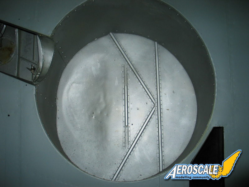
The flattened inner profile beside the bulge is interesting though.

All the best

Rowan
robot_
_VISITCOMMUNITY
United Kingdom
Joined: March 08, 2009
KitMaker: 719 posts
AeroScale: 691 posts
Posted: Monday, February 11, 2013 - 09:09 AM UTC
I think it is possible that the floor of the wheel well is circular, but as the wing's upper surface (i.e. the floor of the well) and the lower surfaces are at an angle to each other (due to dihedral and the tapering thickness of the wing) the shape made when the well intersects the lower wing surface is not circular.

Anyway, looks very nice. I hope the fit of the parts is good- the two-part wing root fairing could cause trouble if the fit is less than perfect.
warreni
_VISITCOMMUNITY
South Australia, Australia
Joined: August 14, 2007
KitMaker: 5,926 posts
AeroScale: 2,201 posts
Posted: Monday, February 11, 2013 - 09:22 AM UTC
I think you are correct Rowan and it is indeed slightly oval. That is of course if it is an original untouched by restorers Spitfire.. (and now it is my turn for the ineviable comment) with all the subjects available out there did we REALLY need another Spitfire?
Merlin
Staff MemberSenior Editor
AEROSCALE
#017
_VISITCOMMUNITY
United Kingdom
Joined: June 11, 2003
KitMaker: 17,582 posts
AeroScale: 12,795 posts
Posted: Monday, February 11, 2013 - 09:42 AM UTC

Quoted Text

...and now it is my turn for the ineviable comment) with all the subjects available out there did we REALLY need another Spitfire?


Hi Warren

I'll get in before Mal on that one... YES!

As Jean-Luc says, this could be the first easily buildable accurate Mk.IX yet. I know - if I'd won the lottery, I'd have bought the ICM moulds years ago and sorted out the production issues - but, back in the real world, this looks like a real cracker!

With regard to the wells, I wouldn't be surprised if Edgar Brooks can settle any debate with some original engineering drawings.

All the best

Rowan
EdgarBrooks
_VISITCOMMUNITY
England - South East, United Kingdom
Joined: June 03, 2006
KitMaker: 397 posts
AeroScale: 384 posts
Posted: Monday, February 11, 2013 - 10:08 AM UTC
Where the Spitfire wheel enters the wing is a perfect circle; where it finishes is also a perfect circle, but, because the wheel moves back, as it retracts, the top circle is behind the lower one, and the side walls slope because of this.
From below, at certain angles, you get an optical illusion that the well is an oval, and only a Supermarine drawing is likely to give the full facts.
To get the well entirely correct, the manufacturer would have to supply the walls as separate items, with all the fit difficulties that would entail.
Edgar
TedMamere
_VISITCOMMUNITY
Moselle, France
Joined: May 15, 2005
KitMaker: 5,653 posts
AeroScale: 4,347 posts
Posted: Monday, February 11, 2013 - 10:13 AM UTC
Hi Edgar,


Quoted Text

the manufacturer would have to supply the walls as separate items,


This will be likely the case with the new Eduard Spitfire kit. So the openings should be round on the wings...

Jean-Luc
EdgarBrooks
_VISITCOMMUNITY
England - South East, United Kingdom
Joined: June 03, 2006
KitMaker: 397 posts
AeroScale: 384 posts
Posted: Monday, February 11, 2013 - 10:17 AM UTC
Merlin
Staff MemberSenior Editor
AEROSCALE
#017
_VISITCOMMUNITY
United Kingdom
Joined: June 11, 2003
KitMaker: 17,582 posts
AeroScale: 12,795 posts
Posted: Monday, February 11, 2013 - 10:29 AM UTC
Hi Edgar

Great to see you come to the rescue!

Although... (and playing Devil's advocate here!) that doesn't match the flattened outline of the interior of the well in the photo?... Any idea what's going on there?

All the best

Rowan

EDIT: Ouch! Shoving that drawing into Photoshop - the outlines, aren't truly circular... Maybe distorted at some point? - if I rotate it to get one vertical true, the other is off...
TedMamere
_VISITCOMMUNITY
Moselle, France
Joined: May 15, 2005
KitMaker: 5,653 posts
AeroScale: 4,347 posts
Posted: Monday, February 11, 2013 - 10:55 AM UTC
Hi again,

I have edited Edgar's drawing for more clarity... at least for me...

Please correct me if I'm wrong but the red circle means the cutout in the undersurface of the wing (then it is indeed almost perfectly round) and the green one the bottom of the wheel well (then it is a little "ovalish").


The red and green lines I've added are perfect circles by the way. So it seems that Eduard could have superposed both circles (cutout + bottom) and that the openings are in fact too big.

Jean-Luc
EdgarBrooks
_VISITCOMMUNITY
England - South East, United Kingdom
Joined: June 03, 2006
KitMaker: 397 posts
AeroScale: 384 posts
Posted: Monday, February 11, 2013 - 11:09 AM UTC
First, remember that engineering drawings are not necessarily scale drawings, also I had to take the photograph of the drawing from a computer screen, so the chances of it being optically correct are slim, to say the least.
Use the drawing as an indication that the well consists of two overlapping circles, by all means (which is all that I intended,) but don't use it as a scale drawing.
Edgar
P.S. Also bear in mind the aerofoil section of the wing, so the well depth will be less at the rear than immediately behind the wing spar.
TedMamere
_VISITCOMMUNITY
Moselle, France
Joined: May 15, 2005
KitMaker: 5,653 posts
AeroScale: 4,347 posts
Posted: Monday, February 11, 2013 - 11:16 AM UTC
Hi Edgar,

I've edited the picture of the previous post. Even if the drawings are not 100% right, it may be an explanation for the oval wheel wells openings on the Eduard kit.

Now it is late, I'm going to bed. Enough round or oval Spitfire wheel wells. The kit will be fine for me anyway. Have a nice sleep all...

Jean-Luc
Jessie_C
_VISITCOMMUNITY
British Columbia, Canada
Joined: September 03, 2009
KitMaker: 6,965 posts
AeroScale: 6,247 posts
Posted: Monday, February 11, 2013 - 11:20 AM UTC

Quoted Text

The red and green lines I've added are perfect circles by the way. So it seems that Eduard could have superposed both circles (cutout + bottom) and that the openings are in fact too big.


Hence my comment that the problem may easily be corrected with a crescent of plastic card and some sandpaper. 5 minutes' work and it's solved. This is why I said that it's not a reason to pass this kit by.

They seem to have restricted themselves to the C wing in this release. I hope that they're going to release an E wing version in the future, that opens up the possibility for so many different schemes.
GastonMarty
_VISITCOMMUNITY
Quebec, Canada
Joined: April 19, 2008
KitMaker: 595 posts
AeroScale: 507 posts
Posted: Monday, February 11, 2013 - 03:41 PM UTC

The wheel wells are wrong, as I pointed out on a French site a few weeks ago, but, as indicated above, it can be fixed with a bit of work and is not necessarily a deal breaker: The real wells seem to me to have a very slight oval, even at the skin opening itself, but are certainly very close to round, if not actually round:


I am willing to overlook more than that from my Otaki fuselage/Hasegawa wing kit bash, where the Hasegawa wings seems to have the guns very slightly too outboard, and be slightly shy in trailing edge chord towards the wingroot... They also seem to be a bit short in span...

The ICM Mk IX wing initially appeared to be better, and was my first choice, but the wheel wells are over 3 mm (6 inches) too close together! I am very grateful someone pointed this out online, as that really is catastrophic: The issue is really obvious when you know about it: It translates into an odd narrow-track look...

Given all the curves, the Hasegawa wing will have to do: As long as it's a nice overall Spitfire shape, I'm happy...

Could we get a nice large square-on photo of the left side Eduard fuselage half? I would really appreciate it.

Gaston


IainArt
_VISITCOMMUNITY
Northern Ireland, United Kingdom
Joined: September 28, 2007
KitMaker: 26 posts
AeroScale: 20 posts
Posted: Monday, February 11, 2013 - 11:26 PM UTC
Not only the wheel wells in the ICM kit; the legs are too close together as well. I used shims on the inboard side of the leg location and cut away the outboard side to provide the correct spacing. Improves the appearance greatly by removing the 'knock-kneed' look of the standard kit.
TedMamere
_VISITCOMMUNITY
Moselle, France
Joined: May 15, 2005
KitMaker: 5,653 posts
AeroScale: 4,347 posts
Posted: Tuesday, February 12, 2013 - 07:56 AM UTC

Quoted Text

Could we get a nice large square-on photo of the left side Eduard fuselage half? I would really appreciate it.


Mcleod
_VISITCOMMUNITY
Alberta, Canada
Joined: April 07, 2010
KitMaker: 1,028 posts
AeroScale: 939 posts
Posted: Tuesday, February 12, 2013 - 08:04 AM UTC
I like it already, and will be laying out the cash. Even though I've got 19 Spitfires in the stash already.
GastonMarty
_VISITCOMMUNITY
Quebec, Canada
Joined: April 19, 2008
KitMaker: 595 posts
AeroScale: 507 posts
Posted: Tuesday, February 12, 2013 - 10:32 AM UTC

Merci beaucoup Jean-Luc!

Gaston
GastonMarty
_VISITCOMMUNITY
Quebec, Canada
Joined: April 19, 2008
KitMaker: 595 posts
AeroScale: 507 posts
Posted: Wednesday, February 13, 2013 - 06:45 AM UTC
So this is what is observable when Jean-Luc's picture is overlayed to a few really nice side-on photos of the Spitfire Mk IX, (which I used to carve slightly my old Otaki kit, with not too bad outlines itself, if you replace the wings):


The problem in the spine is probably nothing to worry about: Well within the range of the plastic thickness, and thus the easily correctable...

The problem with the windshield is another kettle of fish: The lines I drew (I could not get them straight any better than that, so they are NOT paralell to the tank, and so they end up diminishing the issue rather than clarifying it, unfortunately: Sorry about that!) represent -less rather than more- the mismatch, and this reveals the nature of the problem, as the two white lines are indeed paralell, as they SHOULD be in this view of the outlines of that nose gas tank: The top and bottom of this nose tank portion SHOULD be paralell: It is very obvious in the unretouched picture in Jean-Luc's post that they are not paralell.

This would not be that big a deal if Eduard had moulded the winshield's base with the windshield, and not with the fuselage, as Airfix did on their excellent Mk XII windshield ("Excellence" here being strictly limited to the kit's windshield! It is however noteworthy that this is the best Spitfire windshield in the scale, and this by quite a margin...).

By going the "wrong" route, and moulding the winshield base integrally with the fuselage, Eduard makes carving that nose surface into a more paralell profile much more difficult, since the complicated windshield base shape will be directly damaged by any carving... (If you have a spare Airfix Mk XII windshield, I would recommend considering using that to get around this issue...)

In fact, considering both the front and rear mismatch to the real aircraft's outline, it seems that the whole canopy needs to be brought downward evenly about 0.6- to 0.9 mm, by carving off its entire seating area equally: Delicate, but not all that hard to do...

I doubt that what we see is the effect of lens distortion: In any case, Jean-Luc can easily confirm if the kit part he has shows the front tank's profile to be paralell top to bottom, as it should be, or trapezoidal as the photo suggest...

Again, this is not a huge issue, and it appears this is still by far the best Spitfire ever to be offered in the scale. The separate windshield base, integral to the fuselage, is a dispointment on several levels however (especially for a subject with so many schemes that it should encourage ease of masking and finishing): There is no way this is the best kit ever offered in 1/48th, as Eduard claimed: I still like their I-16s better!... (Best ever quaterscale WWII kit is still, IMHO, a toss-up between the Revell Ju-52 and one of the better Japanese subjects by Hasegawas: F1M, J2M, C6N...)

I will still finish my Otaki, and use it as a comparison to the Eduard kit... The issues I see here will probably keep me from buying as many multiples of it as I did their I-16, but they are not intrinsically a huge deal...

Gaston
Jessie_C
_VISITCOMMUNITY
British Columbia, Canada
Joined: September 03, 2009
KitMaker: 6,965 posts
AeroScale: 6,247 posts
Posted: Wednesday, February 13, 2013 - 07:02 AM UTC
Gaston, you're making a great deal of soup from insufficient oysters. You cannot possibly know whether Jean Luc's picture was taken at exactly 90 degrees normal to the longitudinal axis, yet you are basing your pronouncements on the premise that it was. You are drawing conclusions that the available evidence cannot support.

By all means be wary of new plastic kits. Remember also that no plastic kit anywhere in the history of the world has ever been a 100% true completely factual and absolutely accurate representation of the real thing. Such is impossible.

However, until you have the plastic in your hands and you have compared its shape to the shape of the real thing, you cannot make pronouncements the way you have been about whether it's accurate or not. Relying on photographs is extremely questionable, because you cannot tell what sort of shape errors have been introduced by the lenses, the film (or CCD), the reproduction, the printing and duplicating processes which all happened even before the photos were scanned, uploaded and displayed on your monitor which in turn introduces a whole new raft of errors into the process.

Be cautious and wait and see. The time to rip a kit apart and declare it unbuildable is after you look at the real thing, not when you're looking at pictures on your monitor.

The true test of a model is whether it looks like its subject. It's still far too early to tell whether this model will do that, but all the early indications are pretty good.
 _GOTOTOP