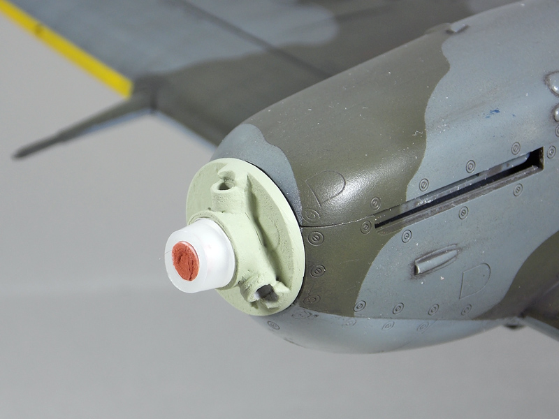
A length of plastic tube has been secured over the kit spindle, after the latter was CAd in place, using filler to fill the internal gap. You can see the drive(?) on the nose plate which the spinner must fit over.
The back plate with the hole drilled out and sitting over the drive and spindle. Not I have had to drill out the holes for fixing the blades.
I cut a piece out of the tapered polythene nozzle of the cap from a small bottle, which tightens nicely over the widened spindle at just the right point. It will be held in place with the spinner is together as there is filled depth to it.
I had to drill out the base of the blades and fit a brass tube (all I had of a suitable diameter) so that there was something to attach the blades to the spinner back plate! I will now have to set something up to ensure that the blades are aligned

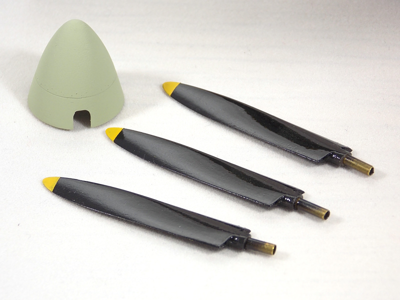
I have yet to weather the prop to match in with the rest of the airframe.
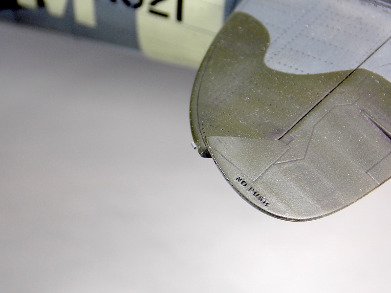
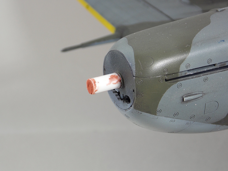
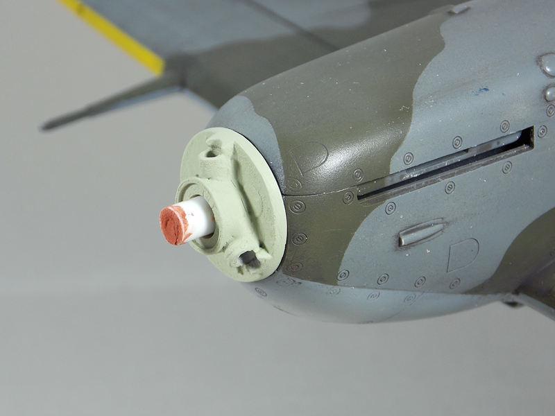
I have also fashioned the IFF antenna fixings for the tail plane. I should have done these before painting so I had to scrape a little paint of the fixing location! The actual device is a tube on a plate with a clamp at the forward end but I have simply used a piece of Albion Alloys 0.3mm aluminium tube (it comes in a pack with 0.3 o.5 0.7 and 0.9 slide fit pieces 300mm long0. To cut simply role uner a blade and it snaps off cleanly, excellent stuff
 It is hardly noticeable and will be even less so when painted, so I don't think that trying to replicate the device exactly (as Chuck would
  ) would have gained (me) anything I bet no other 1/32 Spit has this anyway (well before I posted this ) I still haven't drilled the holes in the fuselage for the IFF wires to enter and again I should have done that before painting. I could have then replicated the insulator as well. I am also trying to work out the exact location for where they enter the fuselage so I am procrastinating again.
Sorry a bit blurred this one, but it shows the location.
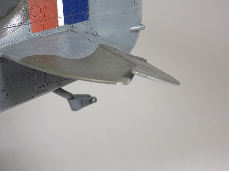
And this one shows that it is a tube