Update 15
A word of advice- Pin EVERYTHING to the structure to keep it securely fastened while handling. Ill explain later.
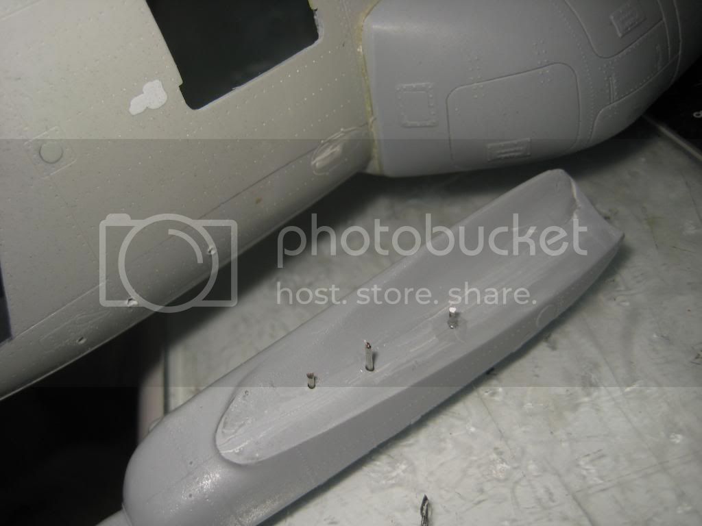
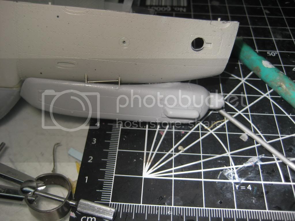
Before I joined the fuselage up I wanted to add the Weather Radar pod. The fit is good. The key is to align the top and keep that flush with the fuselage. The bottom will have a gap as will the aft portion where it fairs around the fuel tank. They are suppose to be there. I drilled though the fuselage in three places within the avionics shelves. This will provide strength and hide the attachment points. I faired my pod in with Apoxy Sculpt and Perfect Putty. There are two attachment points on the bottom of the pod that I scratchbuilt. It is a simple mount. Most will never notice it.
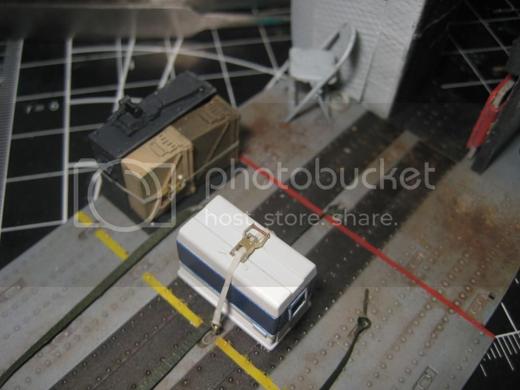
OK it was a moment of truth. I added the stowage and flyaway gear. Cargo was strapped down as in the real thing. How to do this? I used some brass PE buckles from CSM Designs. They are perfect. At first I primed them in the hope to paint them
.brass. Duh. So I scraped off the primer and was quite happy with the look of the tiedowns.
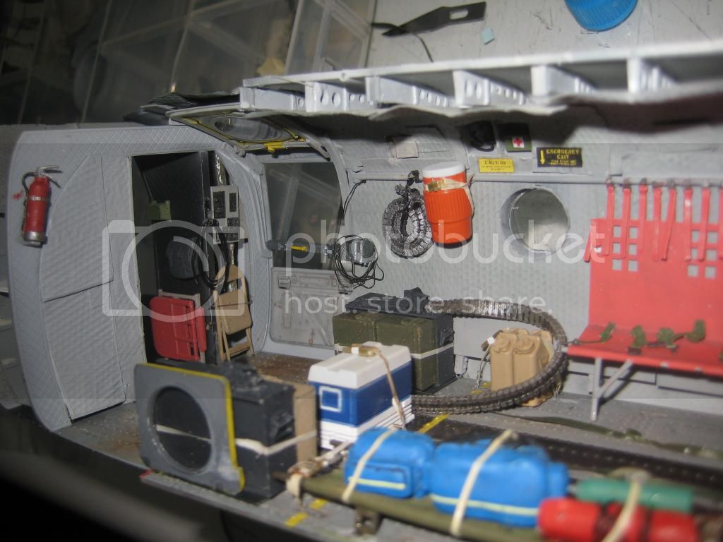
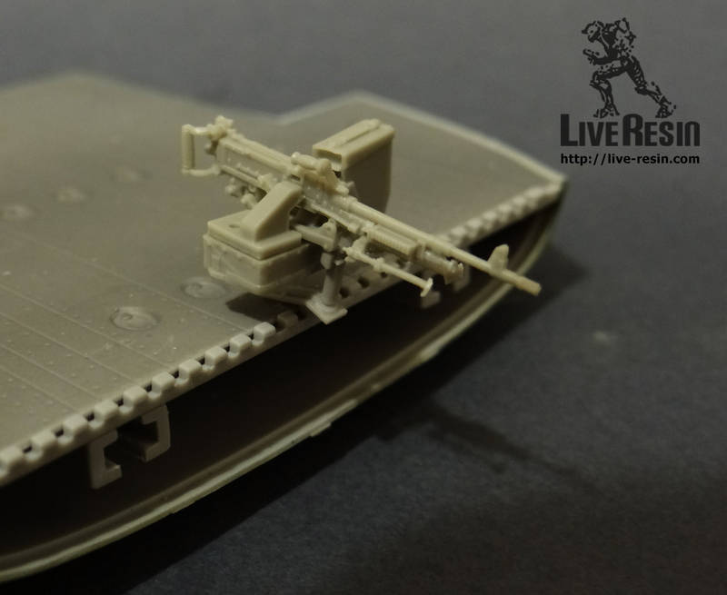
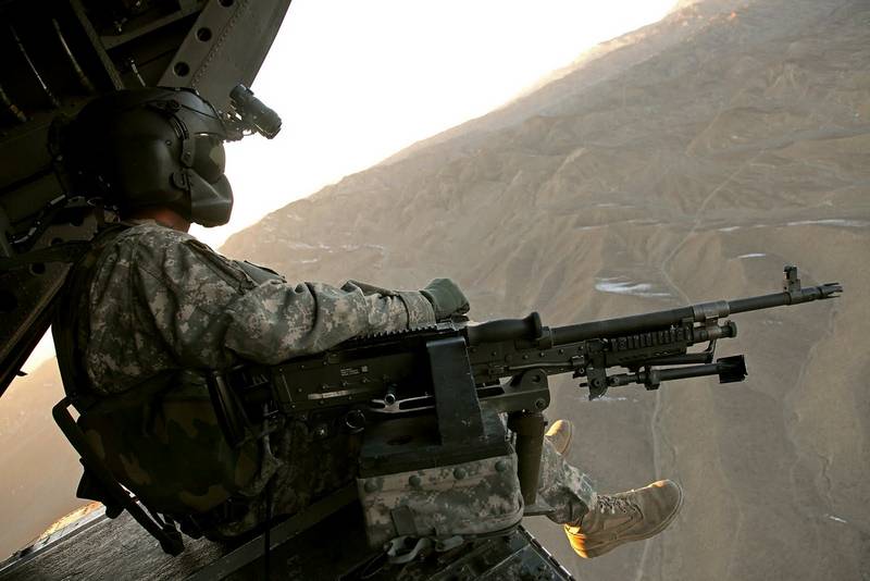
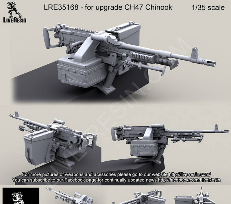
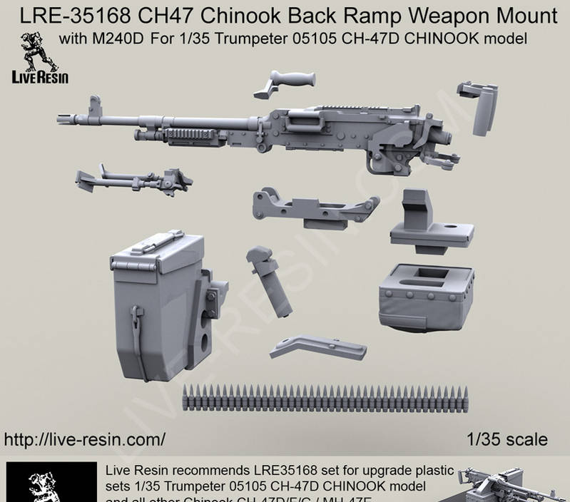
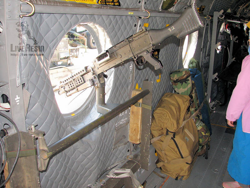
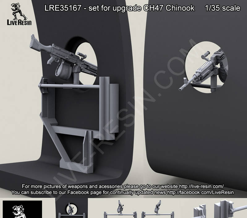
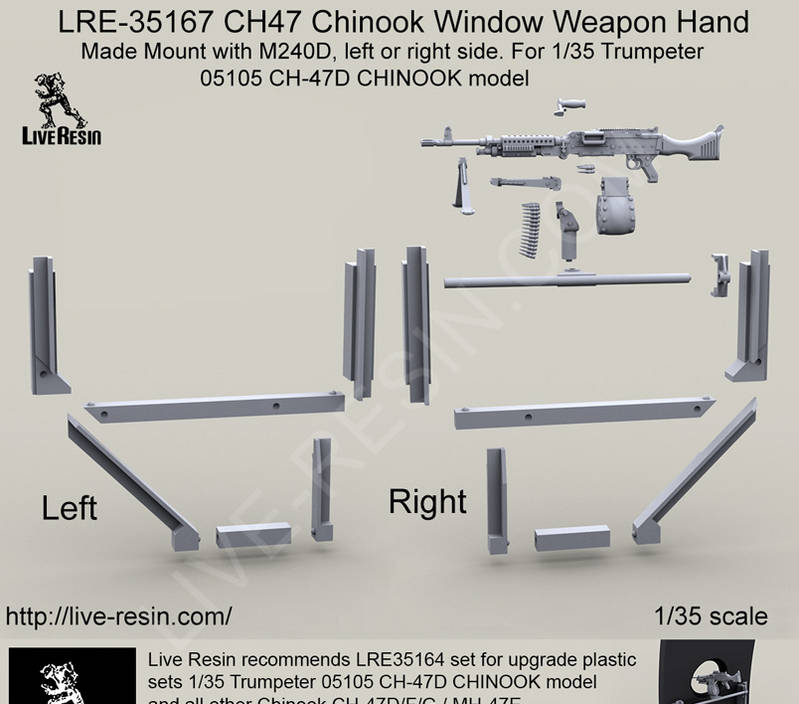
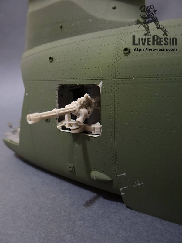
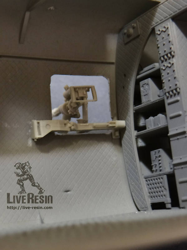
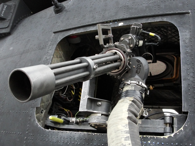
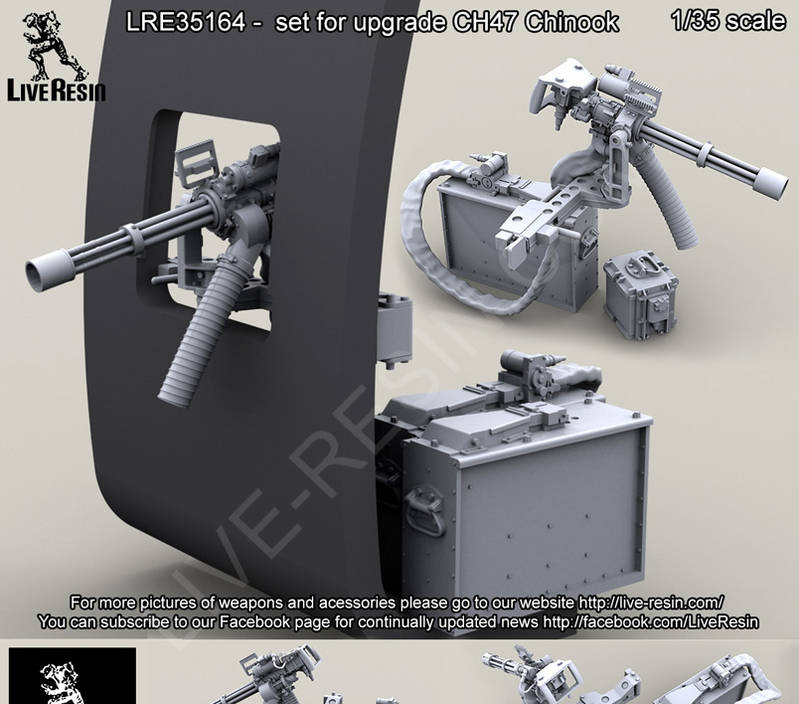
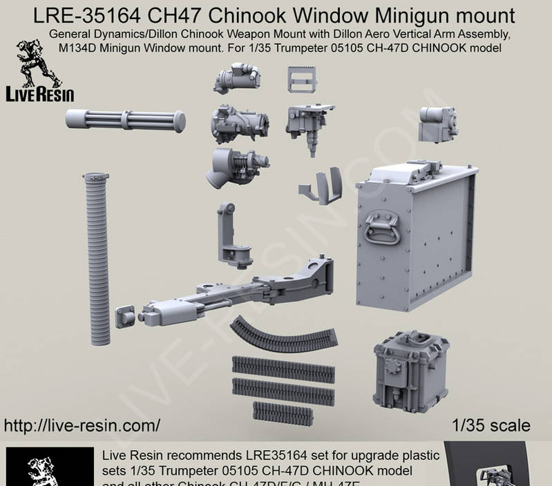
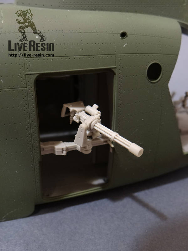
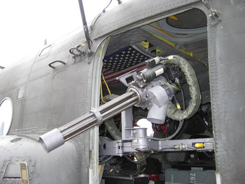
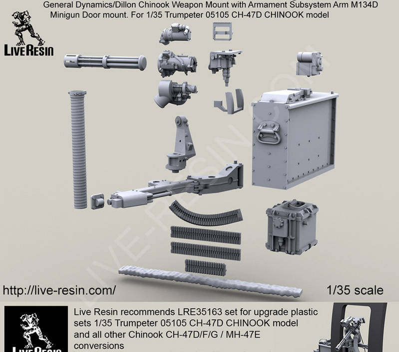
The floor was attached to the right side as it had the most seats and would be the hardest to get to plus it had the opening for the heater closet. I learned that the refueling panel was located in the heater closet. See the pictures for where it is located. I used a Cobra Company panel from their aft pylon set. It looked the part and fit perfectly on a sheet of styrene. Another thing that I did was I decided to use flexible ammo chutes from the Cobra Company as the chutes provided by Live Resin were too small to fit from the ammo cans to the breaches of the guns. Besides the chutes have to be heated and molded into place, this was beyond my capability. I was able to maneuver them with a heat gun to get the big curve but without the guns installed there was no way I was going to get them to fit once installed. A hint when using the flexible ammo chutes is to tape the chutes outside the door opening.
The ammo cans are not attached to the floor by straps. They are actually attached to a semi-rectangular piece of aluminum which fits into the tiedowns on the floor. The ammo cans are then strapped to that, maybe a spare ammo can and a water can or two. The MH-47E only had one ammo can per side and no battery boxes. They were powered from the aircraft. The battery box and extra ammo can was added at a later date and to the MH-47G. My aircraft did not have the can and battery box.
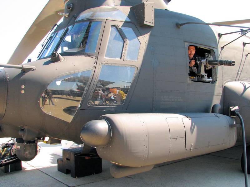
One thing that I found out was that the gunners used folding chairs on combat missions. I used the folding chairs from the Tamiya Command Group set. They are old but they look the part. They are held in place by bungee chords. One person has told me that the Task Force aircraft, especially the MH-47s, are Velcro and bungee chorded together.
I was also told that every MH-47 that was deployed had an American flag in the cabin affixed to the roof. I printed one out on paper and glued it in place. Ive seen them tacked in place and also secured with straps.
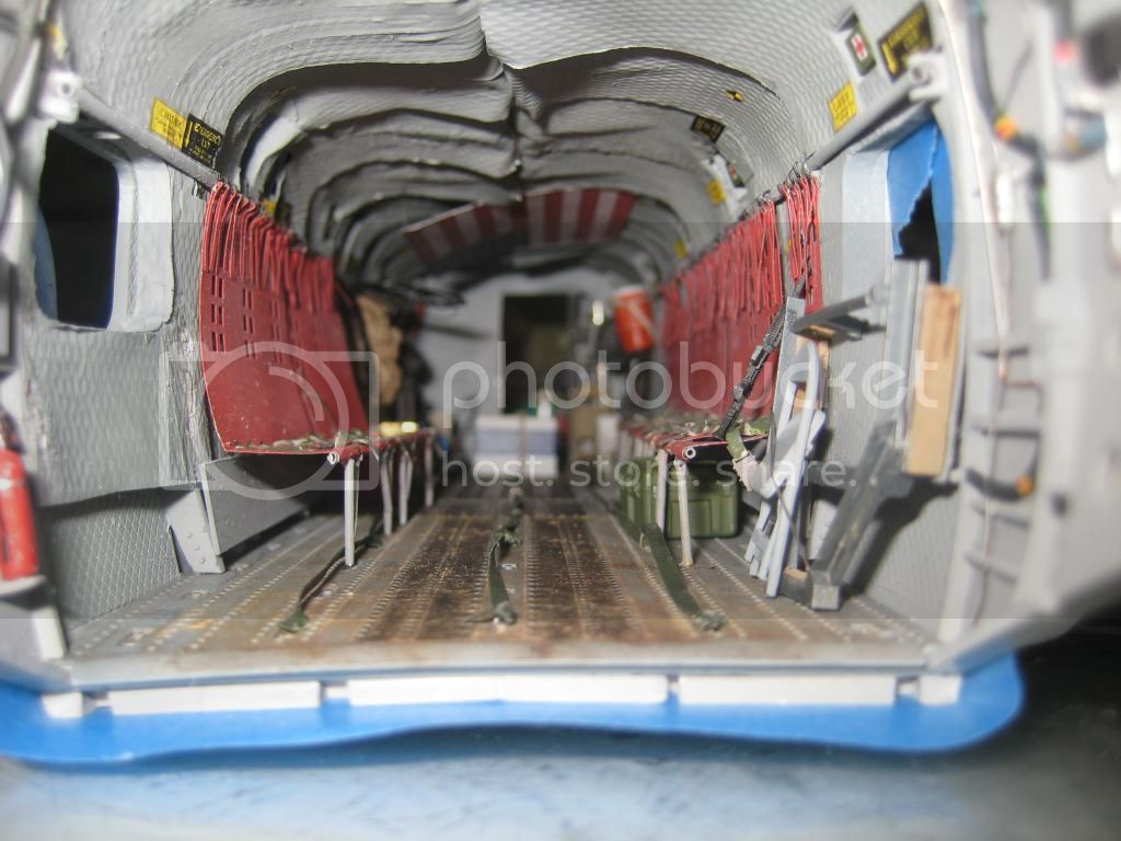
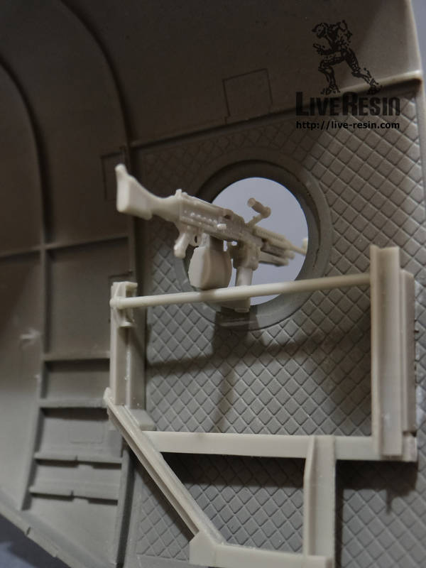
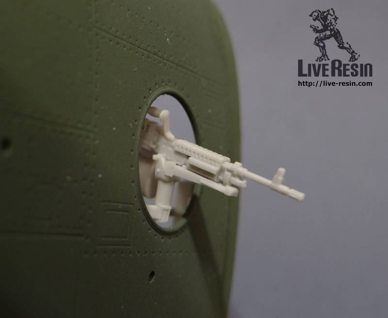
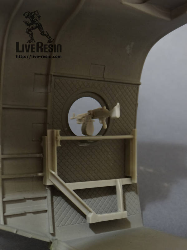
I used a very thin strip of blue tape which is not very sticky to hold the left side seats up while I moved the flooring together so as not to break off the legs. Very carefully I moved the fuselage halves together. The fit was troublesome, but not too bad. The fit of my components was actually very good. One of the Live Resin rear guns moved slightly and fouled the fit. It ended up breaking off. It was not the only thing that broke off.
When I turned the model over a few more things broke free, most noticeably the left side ammo can. This required me to completely rip off the passageway and heater closet to reattach it. I ended up leaving out the two water cans as I couldnt figure a way to add them after they broke free. They cannot even be noticed. I actually felt better after parts were put back together.
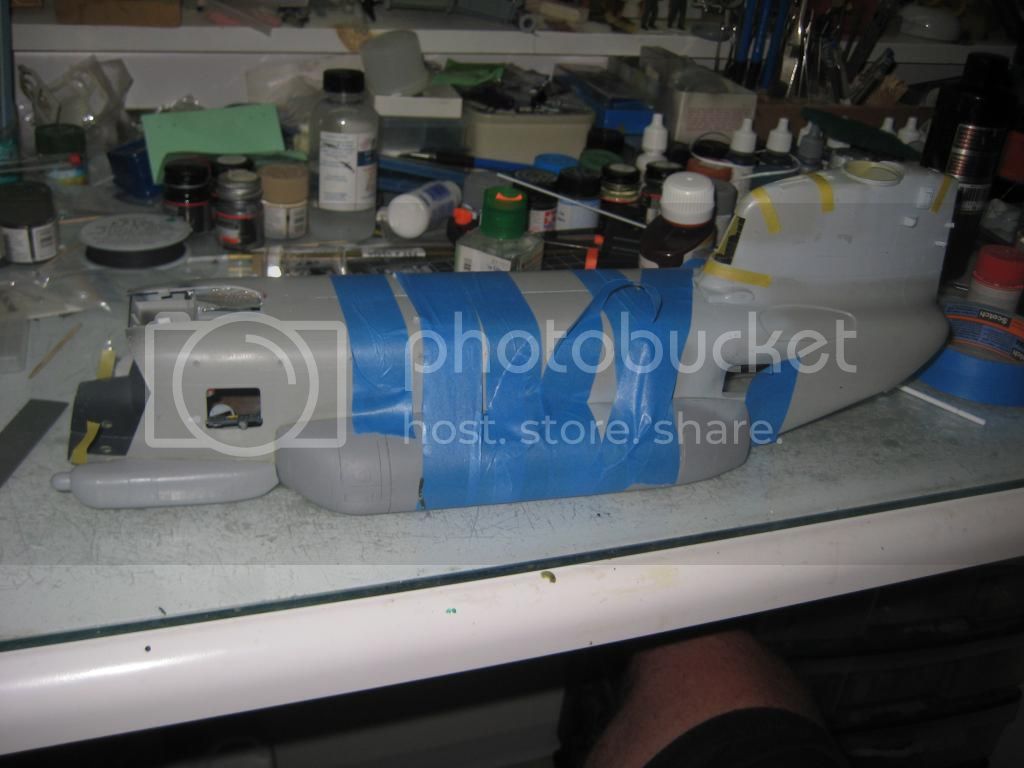
The fuselage halves were held together with painters tape then glued in place with Tamiya cement and superglue. The fit of the bottom was not as good as I would have liked but certainly not anything too bad. Ive seen worse. They were filled with superglue and Apoxy Sculpt. Once it was all filled up there was need to rescribe and re-rivet the belly. This was a tedious task but it worked out nicely.
Painters tape holding it together.
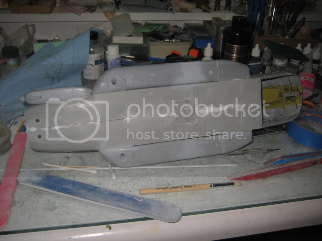
Belly after filling
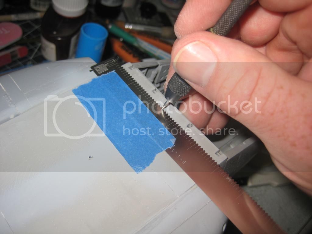
Re-riveting the belly of the beast
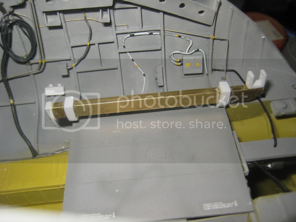
Most MH-47s have Fast Rope attachments in the back of the helicopter. Since I had the helicopter upside down now was the time to scratchbuild it. I used some brass beam and sanded an angle into them. After that I used styrene to build up the mounts and the mounts. Holes were drilled into the model to accept the attachment at any time. I used 90 weight parachute rope for the actual fast ropes. They come in three sizes on the real aircraft, 30, 60 and 90 foot lengths depending on the mission. I was really happy with the results.
I will sell the rope to anyone who wants it. Contact me at
[email protected] . Ill sell them in scale 60 foot lengths with two per package for $10USD.
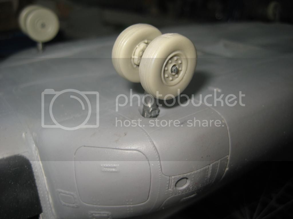
It was time to add the landing gear. Now I figured that this would be no problem. Was I wrong. The forward gear seems to be made from a very strong white metal. That cant be said for the aft landing gear or the lower part of the forward gear. They are fragile and literally fall apart. I am lucky that I had two D model kits because I needed both of them. Even then some I had to be glued to hold in place. Overall they went together fine after a breakage here and there. I sure wish Scale Aircraft Conversions would come out with a set that wouldnt fall apart.
I used Cobra Companys wheels and brake cylinders as they are nicer and easier to use than the kit vinyl ones.
Front landing gear after being modified and pinned in place.
It was time to add the back portion of the fuel tanks. These are easy to add and fair in. I did paint the area behind and under them as they would be difficult to get to later.
That is all with this update. More to follow as I can get to it. Next iteration, the cockpit and canopy.