World War II
Discuss WWII and the era directly before and after the war from 1935-1949.
Hosted by Rowan Baylis
FRROM 1/32 IAR-81C Build Review
DougN1
_VISITCOMMUNITY
Georgia, United States
Joined: August 08, 2011
KitMaker: 410 posts
AeroScale: 409 posts
Posted: Saturday, August 09, 2014 - 09:28 AM UTC
Joel - The real aircraft did not have white surrounds on it's instruments. Radu's book does not show them on any photos, however the IP drawings do use a thin white surround to differentiate the instrument from the black background. Maybe that is why the decal maker put them there.

Time for an update! Been crazy busy with work the past few weeks, but found a bit of time to make some progress on this build.

While making some progress on the cockpit and doing some dry fitting, I found that in my case the top of the IP slanted a little rearward when installed, so I recommend you sand down the area indicated if you run into the same issue during your dry fitting:
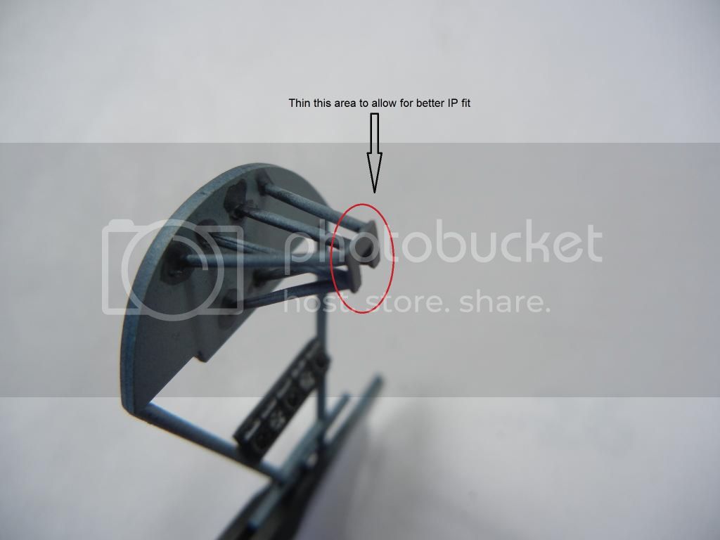


I also decided to assemble the wing. When prepping the parts I noticed that the port upper wing has some surface imperfections that need to be sanded away (took about 2 mins) as indicated in here:
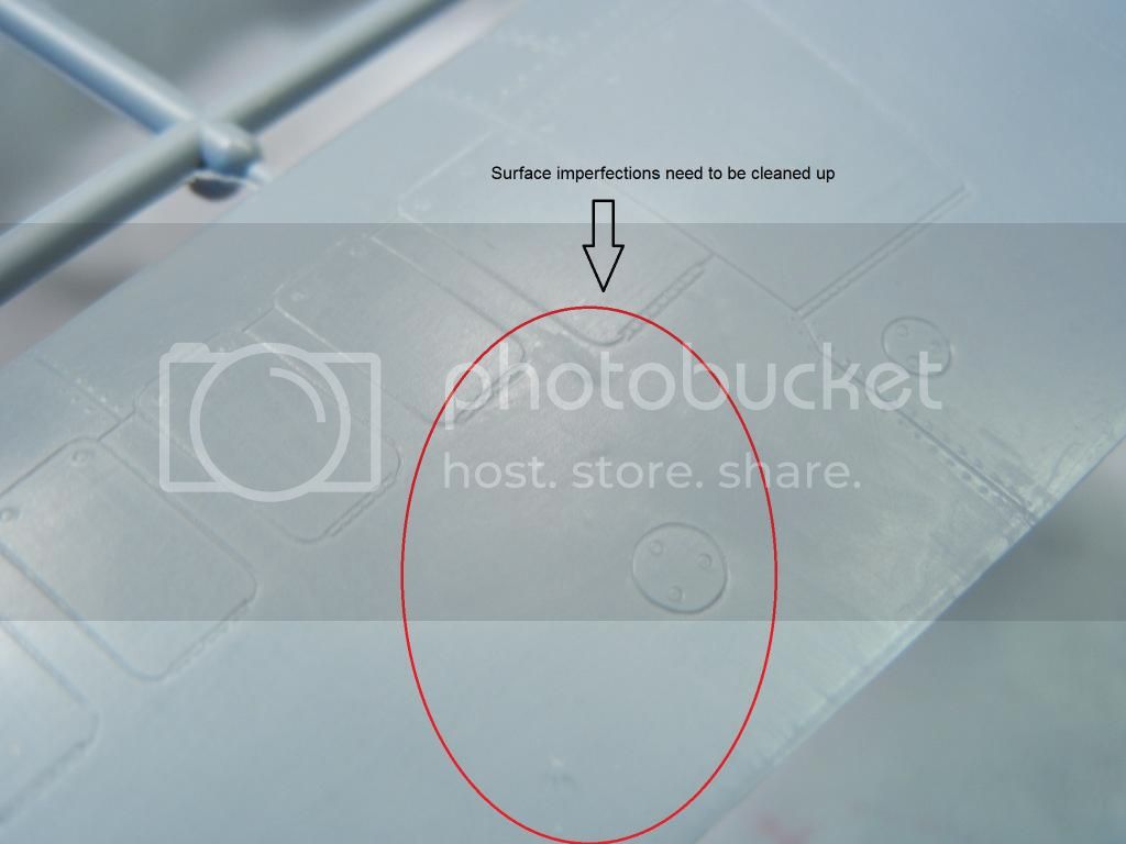


I checked my other kit and it was identical, so I'm guessing all kits will have these imperfections.

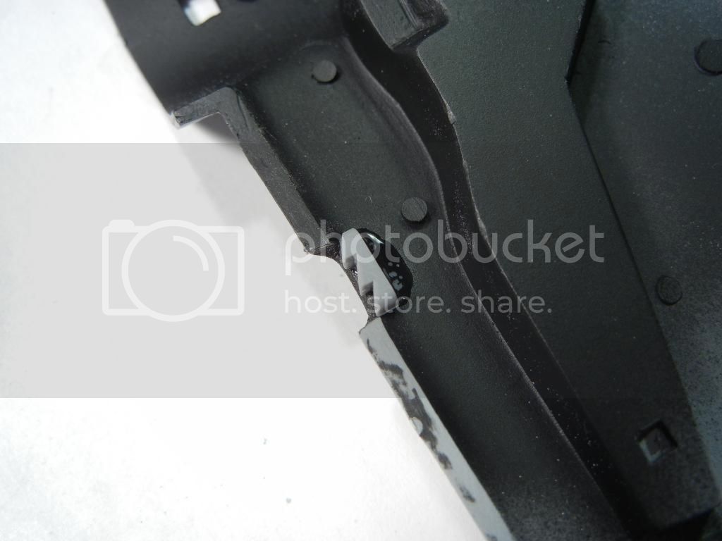
There are a lot of injector release pin marks on the inside surfaces, but only these two seemed to have any impact on fit:
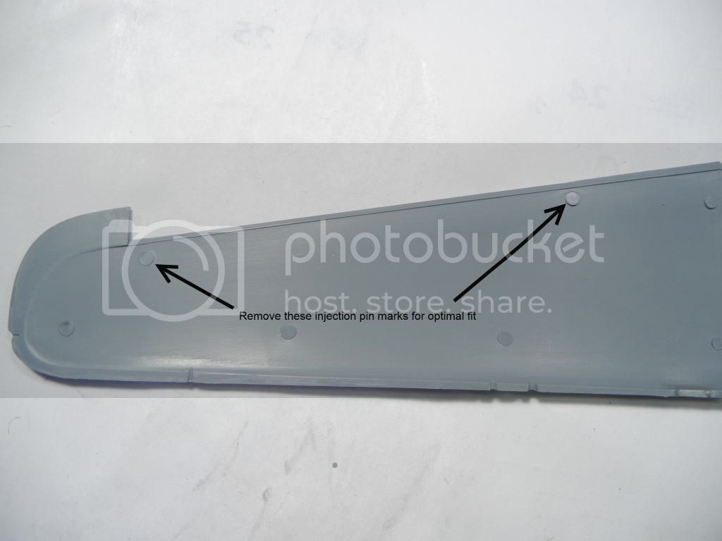


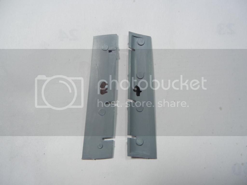
After getting everything cleaned up, I installed the two oil radiator duct "screens" as shown here:


After that, I was able to glue the upper and lower wings together. Interestingly, I noticed that both upper wing parts had the same curved "gap" in the center area of the leading edge:
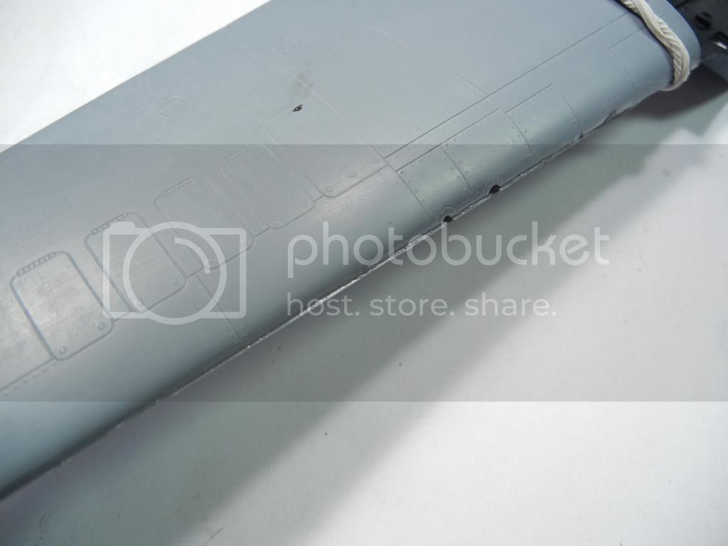


Fortunately, this was easily addressed with a sanding stick when they were dry.

Again, sorry for the delay and the quick update. Hopefully I'll have more time next week to make some more progress!

Thanks for looking! Comments/critique/questions always welcome!

Doug
chukw1
_VISITCOMMUNITY
California, United States
Joined: November 28, 2007
KitMaker: 817 posts
AeroScale: 729 posts
Posted: Saturday, August 09, 2014 - 01:52 PM UTC
I'd say you were doing this bird proud, Doug- cheers! Pardon me for hanging back on commenting, but I've had a lot of things going on in my life as of late- and things are starting to settle down. I could speculate about the cockpit details- like the circuit breakers of the outboard wind bomb racks. Dubious, in my opinion- but that's never stopped me from adding details like them! That only thing I's say you're cheating on is working in 1/32.

Your build is looking great- and you're doing a great job in pointing out the pluses and the, um, eccentricities of this lovely kit.

Party on, dude!
chuk
Merlin
Staff MemberSenior Editor
AEROSCALE
#017
_VISITCOMMUNITY
United Kingdom
Joined: June 11, 2003
KitMaker: 17,582 posts
AeroScale: 12,795 posts
Posted: Saturday, August 09, 2014 - 07:41 PM UTC
Hi Doug

Nice one! Sorry - I missed your previous update. Great work as ever.

All the best

Rowan
DougN1
_VISITCOMMUNITY
Georgia, United States
Joined: August 08, 2011
KitMaker: 410 posts
AeroScale: 409 posts
Posted: Saturday, August 16, 2014 - 08:01 AM UTC
Thanks for the comments!

@ Chuk - Thanks, I'm enjoying following your work on the 1/48 kit - better keep moving or I might get done before you And I'd say you're the one cheating working in that tiny 1/48 scale. You just need to make it look like something is there, where in 1/32 you actually have to make it look like what it is supposed to be

Finally got time to get some more done on the kit and post a decent update!

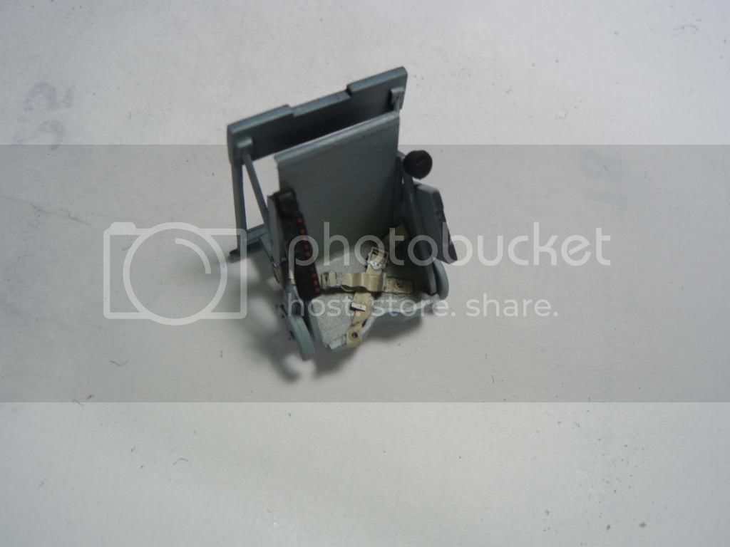
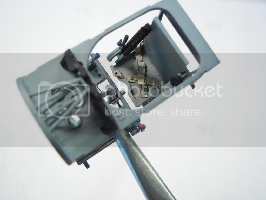
I got the seatbelts installed, and am quite pleased with the results - they look great, especially for PE in my opinion:


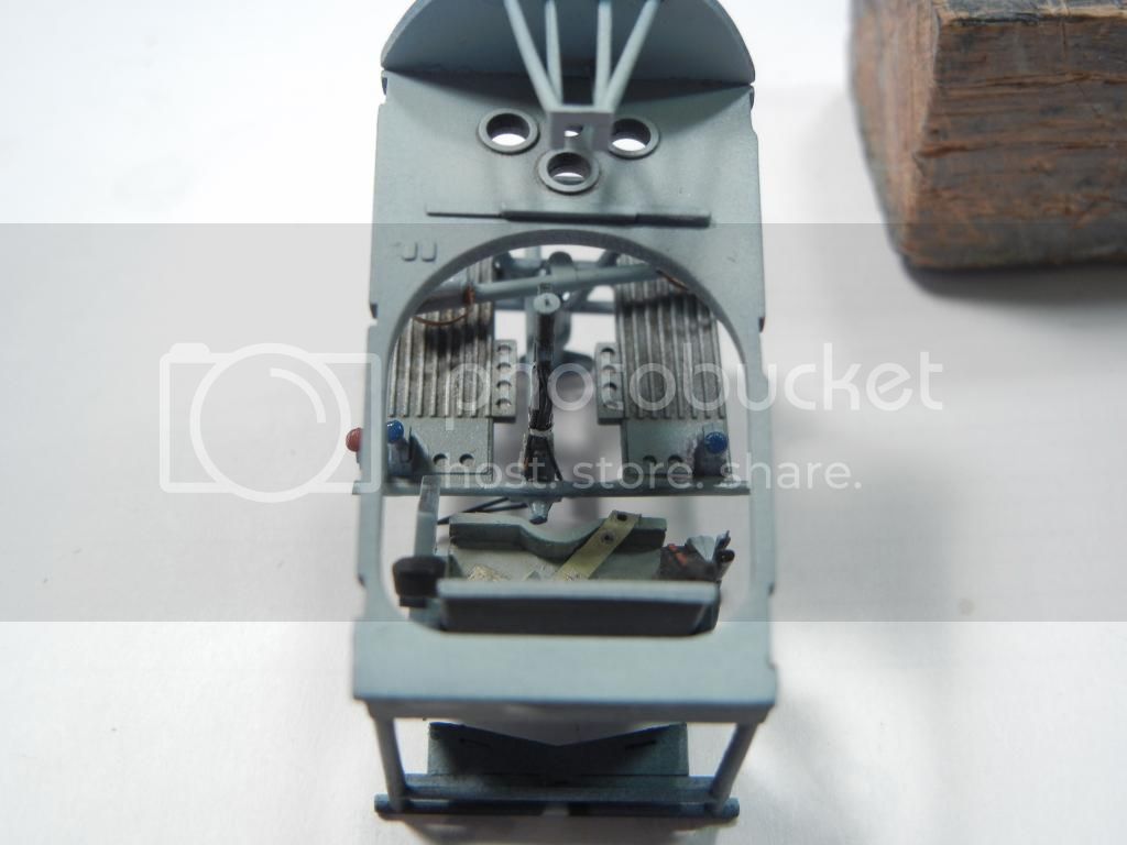
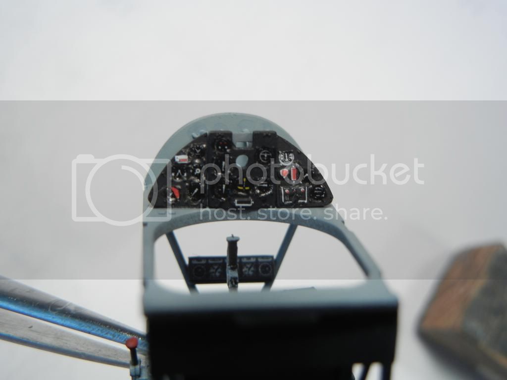
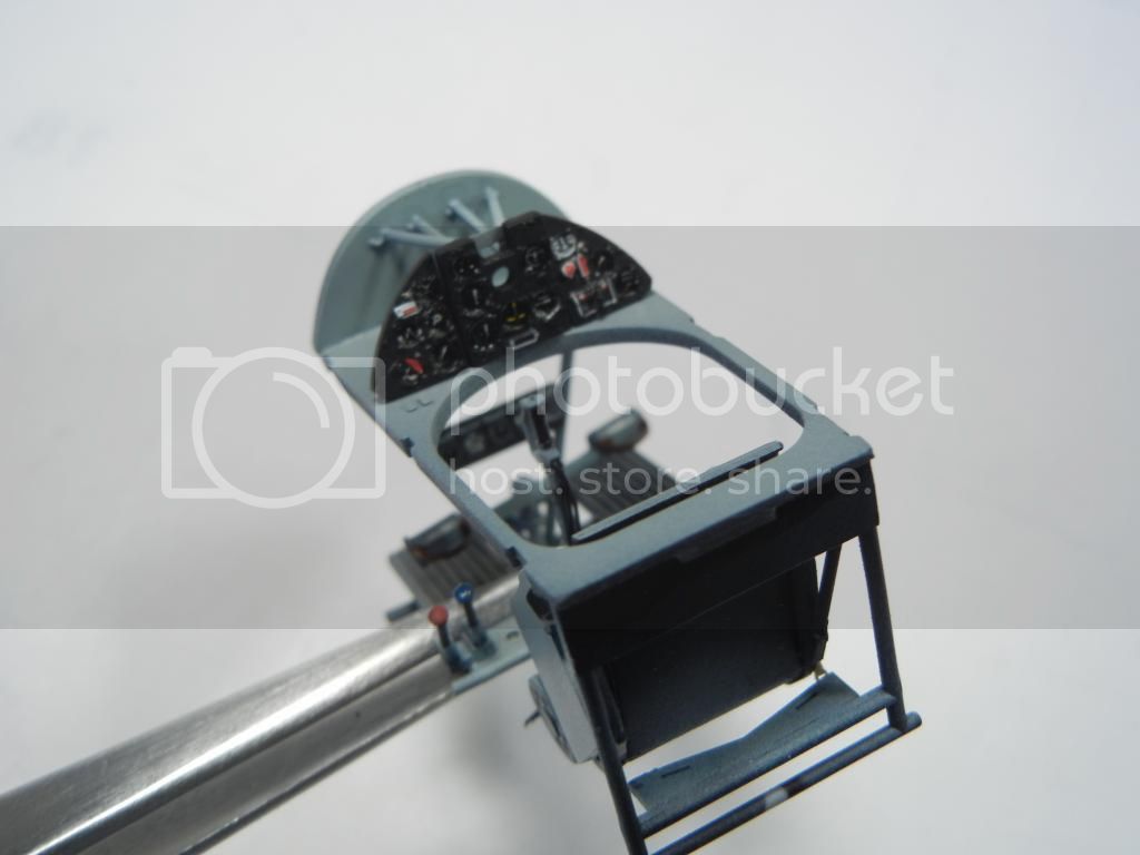
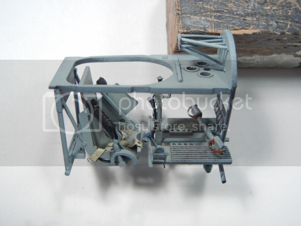
Once that was done, it was time to get the cockpit assembled. I attached the rudder pedal assembly, the heel-boards and the stick to the front bulkhead and let them dry. I then attached the cockpit decking to the front bulkhead and let that dry. Finally, I attached the seat/frame to the rear. Photos of the final result:


The eagle-eyed amongst you will note that the rudder bar is offset as I plan to have my rudder offset

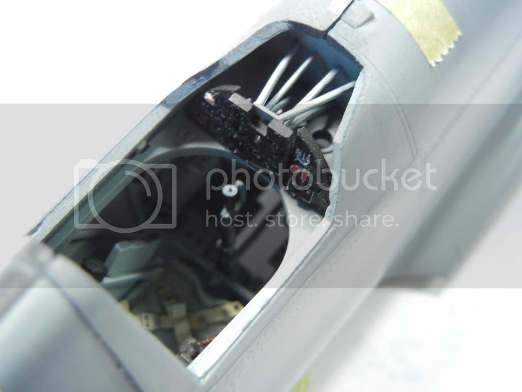
I test fit this assembly into the fuselage halves and all looked fine:


But wait! There's even more! I also attached the 3 IP panels in place:


Fit was great after thinning the mounting point as indicated in my previous update.

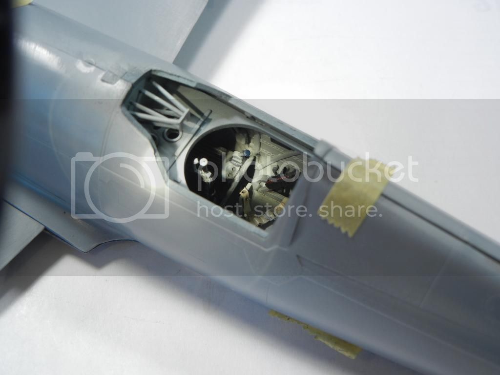
And, finally, a test fit to make sure everything will be fine for final assembly:


I'll do one more check to be sure I haven't forgotten anything, and then it will be time to seal up the fuselage and get on with the remaining items.

I think the cockpit looks quite convincing out-of-the-box. With the decking in place, it seems that the real focus will be anything that is above it as it's hard to see any of the detail under it, even in 1/32 scale. Overall fit is good, especially considering this is a limited run kit.

Next up, engine/cowl and wing control surfaces.

Thanks for looking! Comments/critique/questions always welcomed!

Doug
DougN1
_VISITCOMMUNITY
Georgia, United States
Joined: August 08, 2011
KitMaker: 410 posts
AeroScale: 409 posts
Posted: Friday, August 22, 2014 - 07:11 AM UTC
Ok - another exciting update

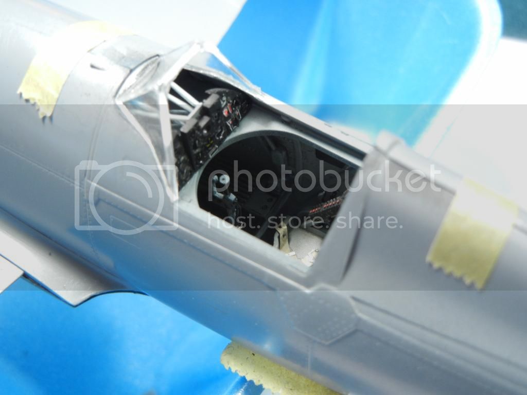
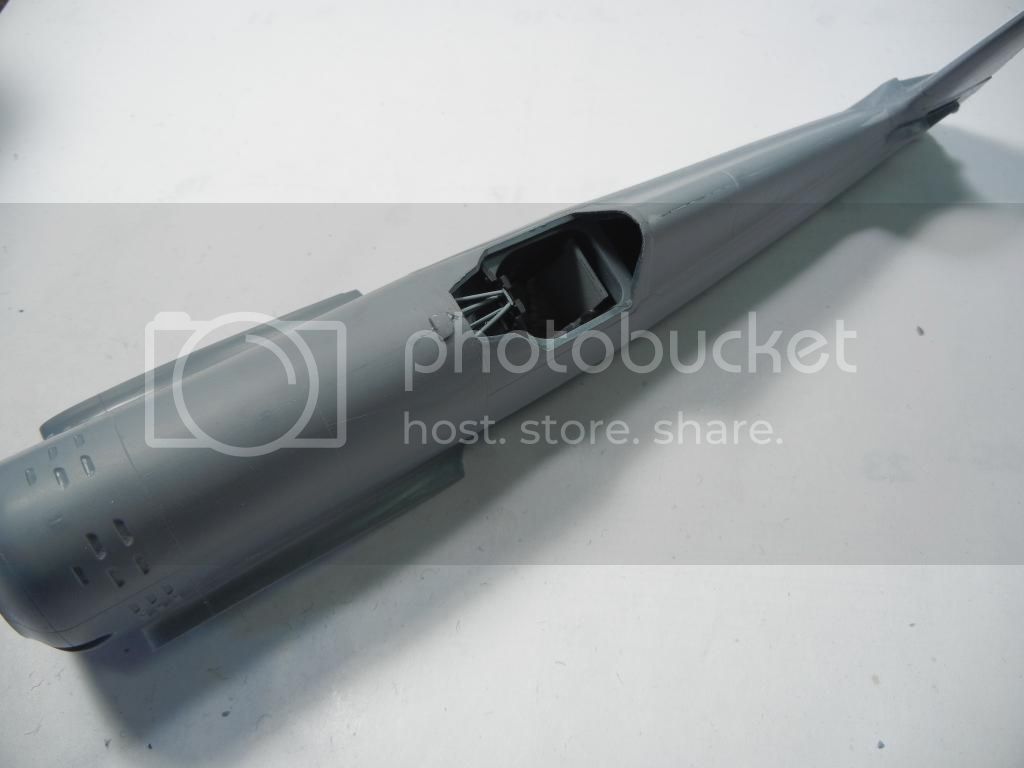
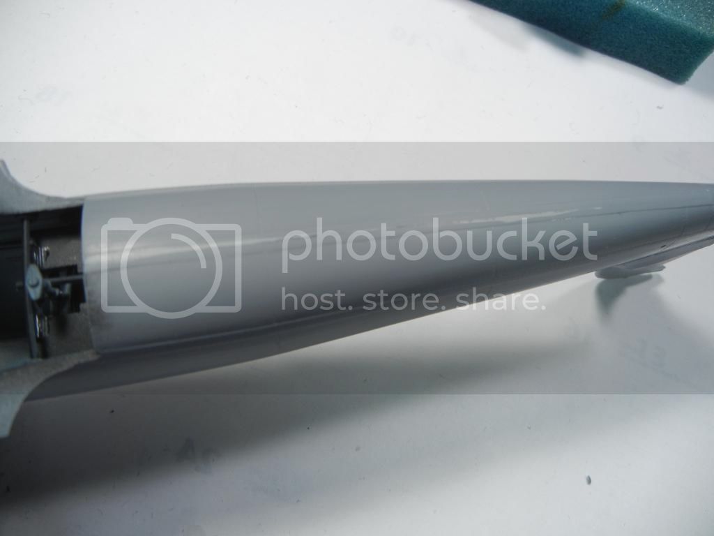
Since I had everything test-fit, it seemed like a good time to just go ahead and glue the fuselage halves together. I left the cockpit loose and since there are no locating pins/tabs on the kit, I started gluing it together at the front of the cockpit to the nose, let that dry and then did the rear fuselage and everything lined up great. After everything dried and intial cleanup of the seams looked good:


After consulting my references, I will need to add the canopy track "notch" in the spine behind the cockpit before it's finished.

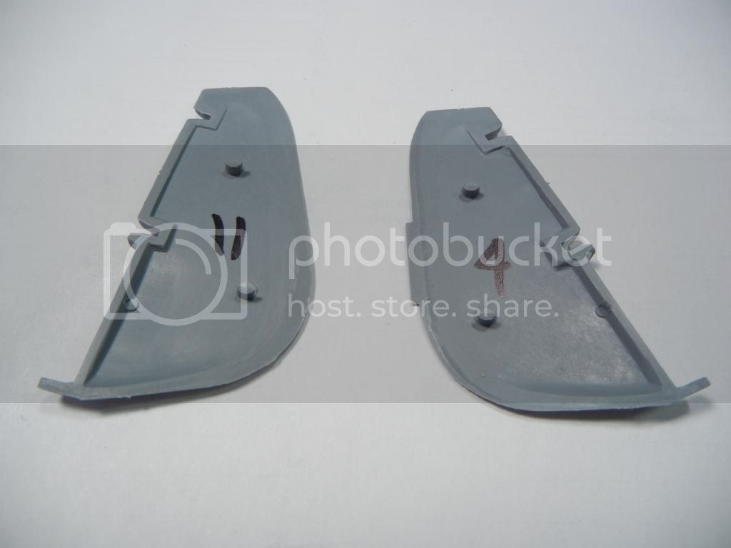
While things were drying, I decided to assemble the control surfaces. While the ailerons were fine. both the flaps and the rudder parts had some big ejector pins remaining:


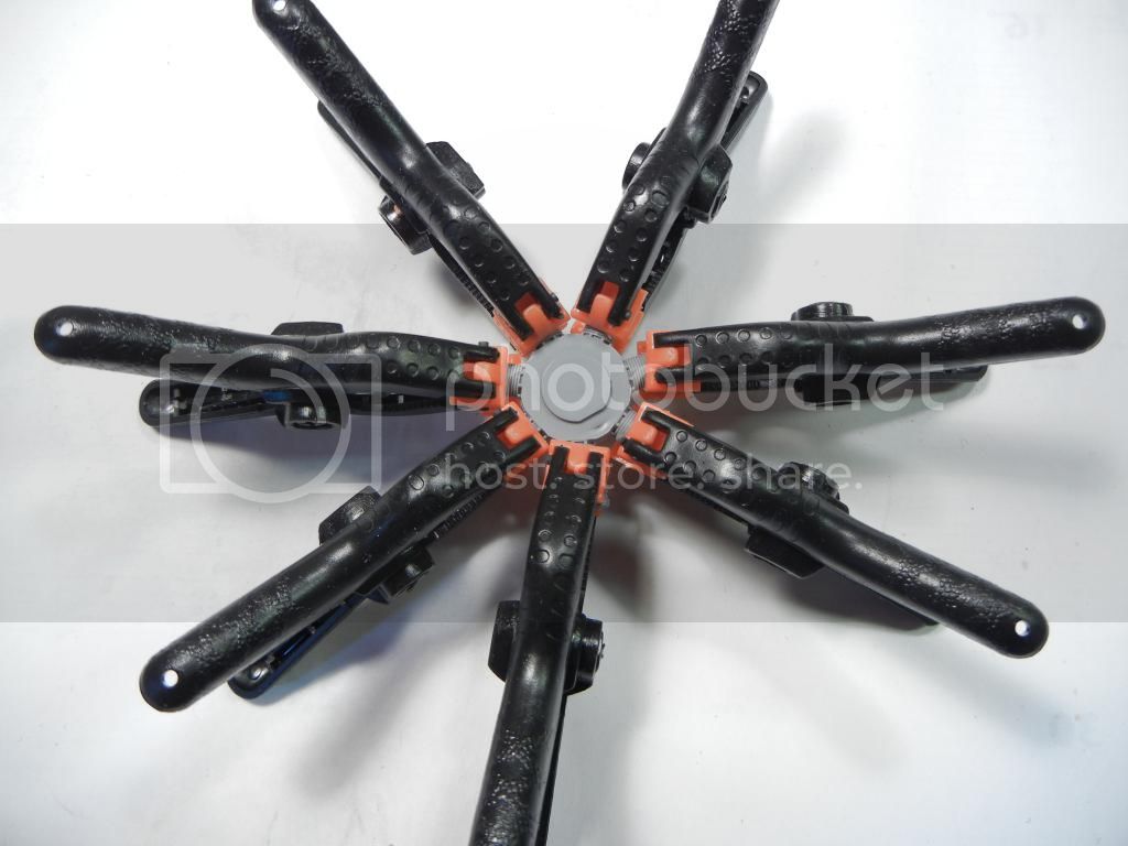
I removed the rudder pins, and while not all of the flap pins interfered with the fit, I removed them just to be safe. I did find that, left untouched, both the flaps and ailerons trailing edges had gaps. I used some clamps and copious amounts of liquid cement to close them up.

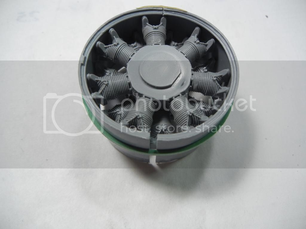
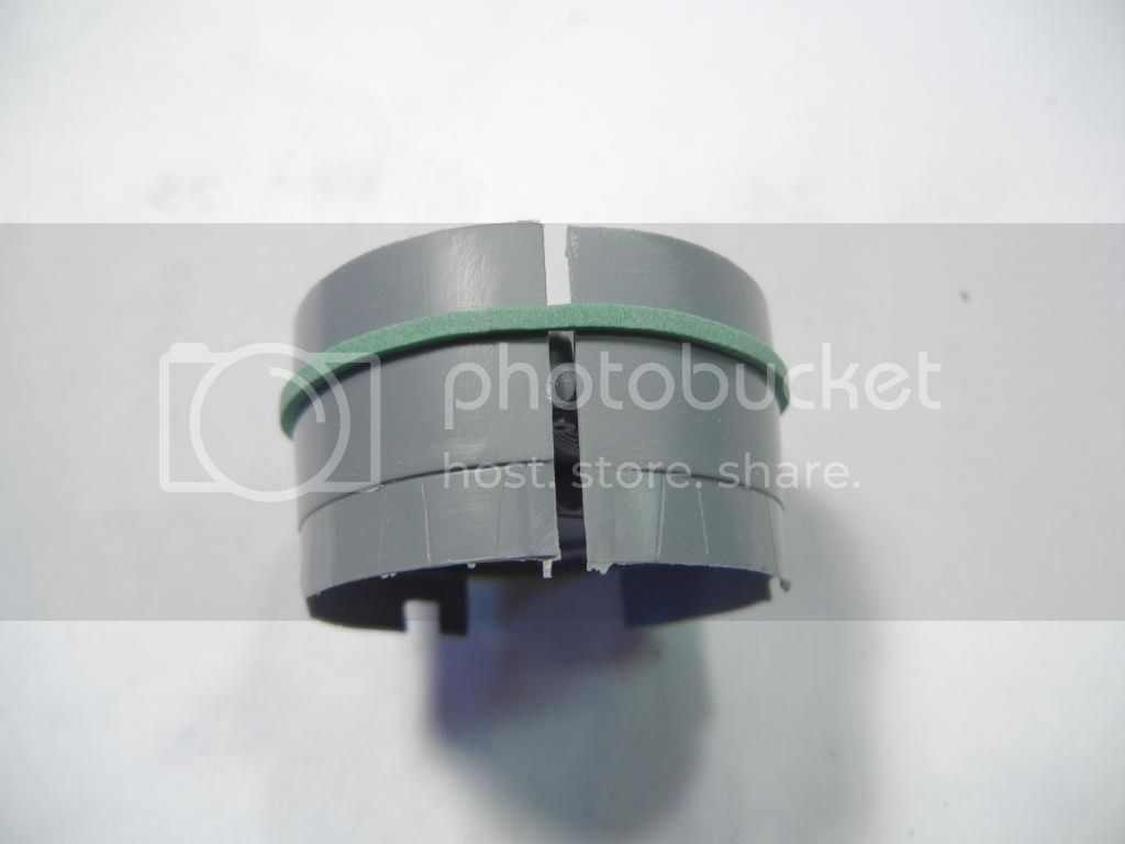
Still having more time, I decided to start on the engine. Interestingly, one set of cylinder/crankcase parts almost snapped together for a perfect fit, while the other needed some clamps to get it to fit.


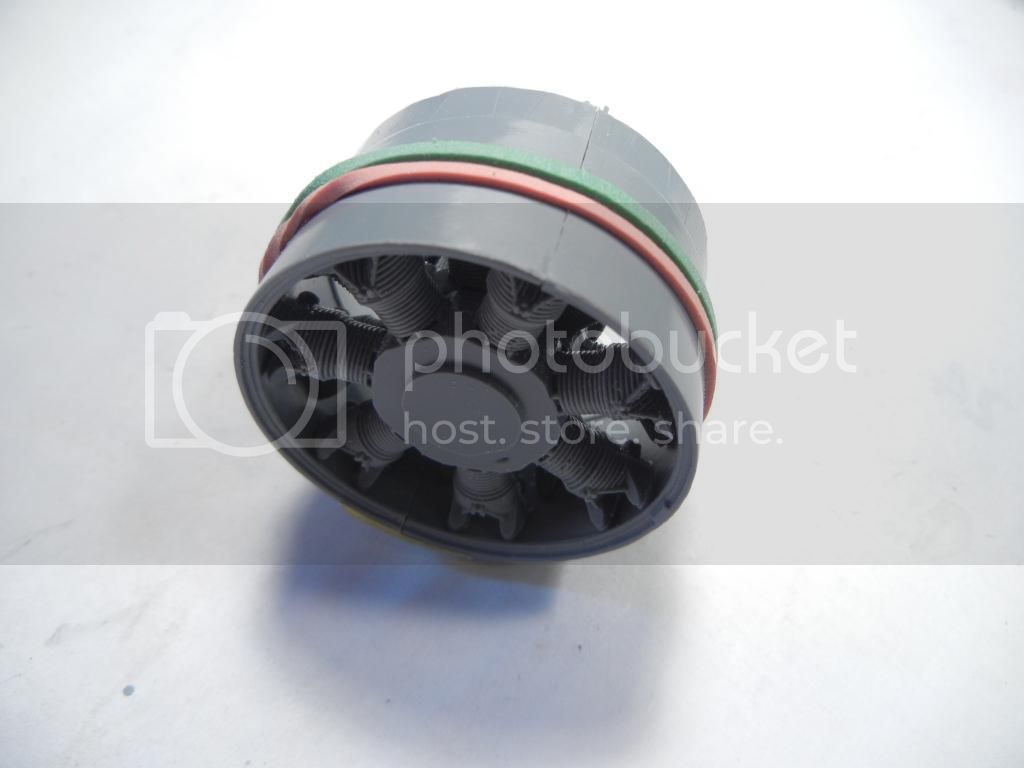
I wanted to get at least that much of the engine together so I could test the fit in the cowlings, as they are pretty thick. It turns out that things are a bit tight as expected:


I thought about it, and decided I did not want to risk warping the cowling parts by thinning them to get a better fit. Since the engine is not very visible in the cowl, I decided to take the needed material off the tops of the cylinders. So out came my friend, Mr Sanding Stick, and after some sanding, everything fit much better:


That's all for this week - thanks for looking! Comments/questions/critique always welcomed.

Doug

Joel_W
Staff MemberAssociate Editor
AUTOMODELER
_VISITCOMMUNITY
New York, United States
Joined: December 04, 2010
KitMaker: 11,666 posts
AeroScale: 7,410 posts
Posted: Sunday, August 24, 2014 - 03:19 AM UTC
Doug,
Interesting approach to the cowl issue. While I can only see the after sanding of the tops of the rear cylinders, they still look just fine. All the front bank will need is push rod casings and spark plug wires.
Joel
Merlin
Staff MemberSenior Editor
AEROSCALE
#017
_VISITCOMMUNITY
United Kingdom
Joined: June 11, 2003
KitMaker: 17,582 posts
AeroScale: 12,795 posts
Posted: Sunday, August 24, 2014 - 04:58 AM UTC
Hi Doug

Azur warned in an on-line update that the cowl would be tight - but that really is pretty tight!

In a way it's encouraging to see the skills we've painstakingly built up over the years with short-run kits won't be entirely wasted with the new breed boasting the kind of fit that we could only have dreamed of in years gone by.

All the best

Rowan
Holdfast
Staff MemberPresident
IPMS-UK KITMAKER BRANCH
#056
_VISITCOMMUNITY
England - South West, United Kingdom
Joined: September 30, 2002
KitMaker: 8,581 posts
AeroScale: 4,913 posts
Posted: Sunday, August 24, 2014 - 07:07 PM UTC

Quoted Text

In a way it's encouraging to see the skills we've painstakingly built up over the years with short-run kits won't be entirely wasted with the new breed boasting the kind of fit that we could only have dreamed of in years gone by.


Nicely put Rowan

And a nice get out Doug, I'll remember this when I build mine The whole thing is looking good; filing down the engine cylinders is no big deal as long as the overall front impression isn't ruined
DougN1
_VISITCOMMUNITY
Georgia, United States
Joined: August 08, 2011
KitMaker: 410 posts
AeroScale: 409 posts
Posted: Friday, September 05, 2014 - 09:46 AM UTC
Thanks guys! You won't see too much of the engine once it's in the cowl, so the bit sanded off the top of the cylinders won't be noticeable at all.

I find regardless of the kit, I mess up enough things to keep my problem-solving modelling skills active

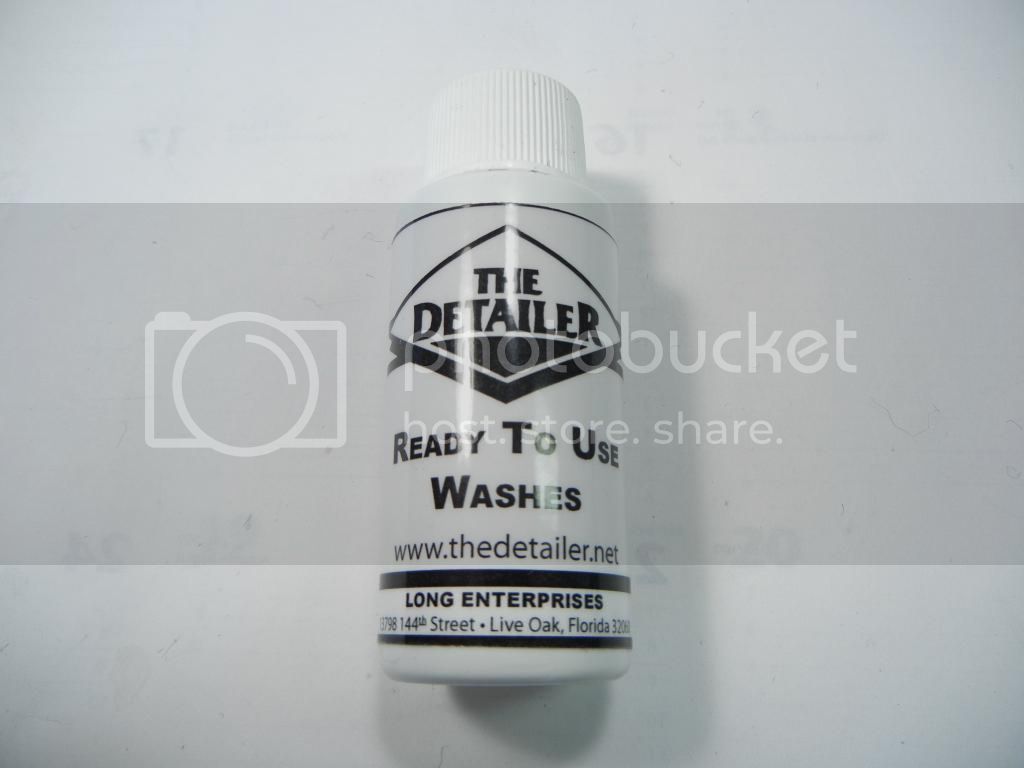
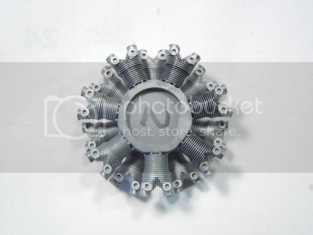
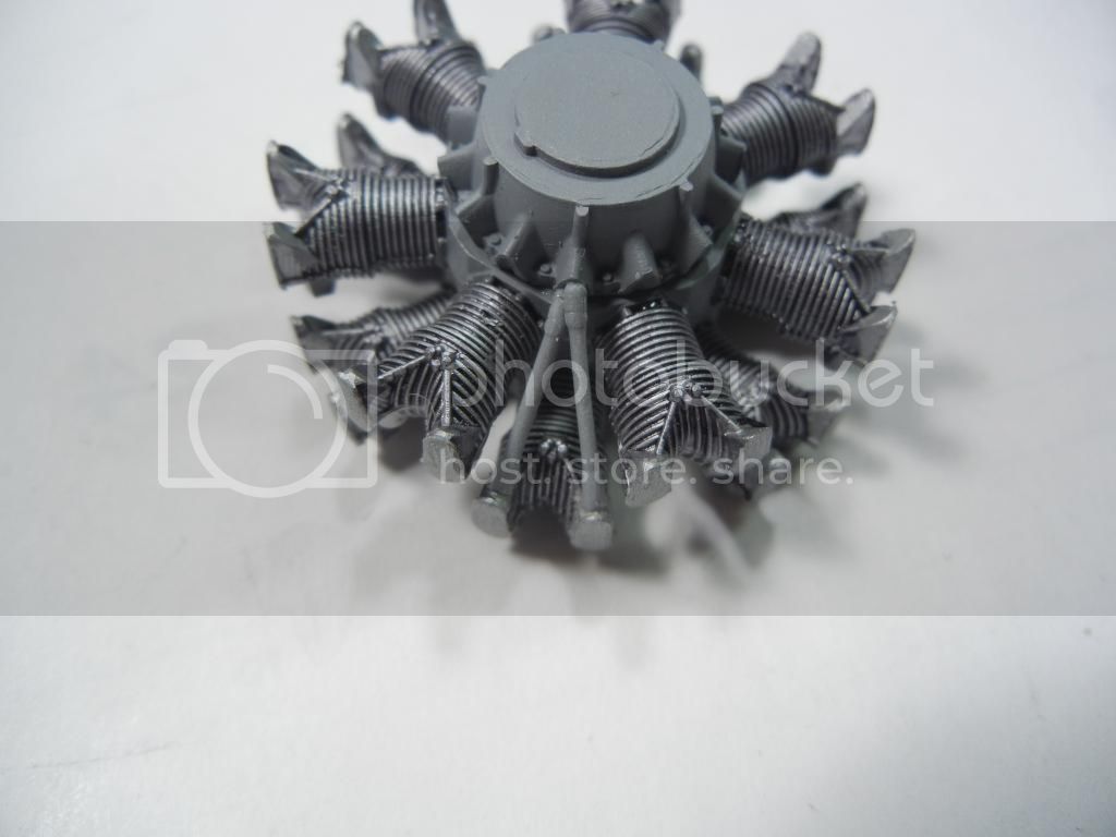
I did a little more on the engine and got the main bits painted. I used Mr Color Silver #8, and then used a brush to paint the grey on the crankcase. After it all dried, I applied a wash of black using this stuff:


I ordered this stuff some time ago after seeing someone else getting good results with it. It is water-based, so goes on nicely over the solvent-based paint. Here you can see the difference between the few cylinders I have applied it to and the "clean" ones:


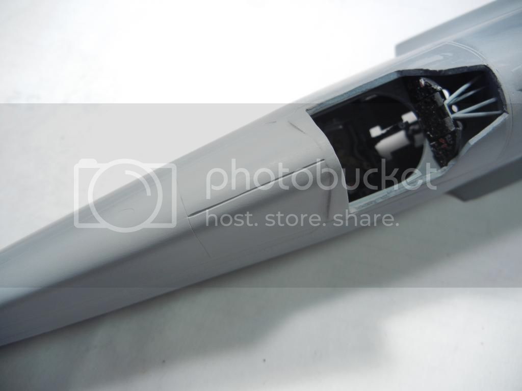
I also spent waaaay to much time on this next bit. There is a "groove" on the spine behind the cockpit for one of the 3 rods that keep the canopy in position. Normally, I would sand the mating surfaces of the fuselage at an angle to create a groove before gluing them together (like I do for 109/110 fuselages to keep the join line).

Since I didn't notice the groove until after I had attached them, I had to cut one in. I taped my straightedge to the fuselage spine, checked it was in position and cut the groove using my P-Cutter. After removing the straightedge and inspecting it, I discovered it was not centered So, I filled it in with superglue, and after it dried and I sanded it smooth, I cut another groove. However, this one ended up with a kink in it. So, after a week of filling, sanding and rescribing, I got it done:


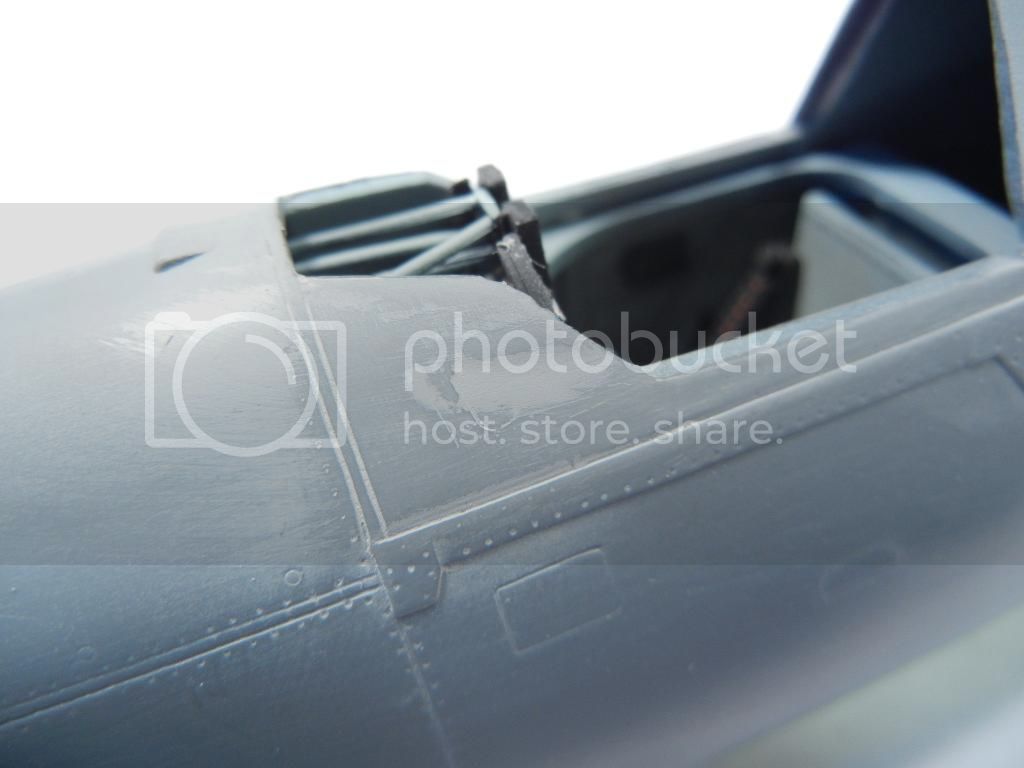
During this process, I also noticed a slight molding flaw in the fuselage near the windscreen. I checked my other kit, and it is present there as well. I sprayed a little primer on it, and then sanded it away to help illustrate where the depression is:


I then slapped some Mr Surfacer on the spot and will sand it out once it dries.

Next up - I need to attach the control surfaces to the wings. I'm still deciding if I want to do that before I mate the wings and fuselage or after. Next update should have the engine assembled as well

Thanks for looking! Comments/quetions/critique always welcome!

Doug
Holdfast
Staff MemberPresident
IPMS-UK KITMAKER BRANCH
#056
_VISITCOMMUNITY
England - South West, United Kingdom
Joined: September 30, 2002
KitMaker: 8,581 posts
AeroScale: 4,913 posts
Posted: Friday, September 05, 2014 - 05:28 PM UTC
Doug, that's groovy
Joel_W
Staff MemberAssociate Editor
AUTOMODELER
_VISITCOMMUNITY
New York, United States
Joined: December 04, 2010
KitMaker: 11,666 posts
AeroScale: 7,410 posts
Posted: Sunday, September 07, 2014 - 12:27 PM UTC
Doug,
That wash really does look good. I've had excellent success using Flory's waster washes. They're fool proof.
Joel
DougN1
_VISITCOMMUNITY
Georgia, United States
Joined: August 08, 2011
KitMaker: 410 posts
AeroScale: 409 posts
Posted: Monday, September 22, 2014 - 09:46 PM UTC
Very funny Mal

I've been busy getting ready for a trip with the family - so had to get lots of work done before that. I did manage to make a little progress on this kit. Now that we have arrived at our destination here in Romania, I thought it would be good to try to post an update

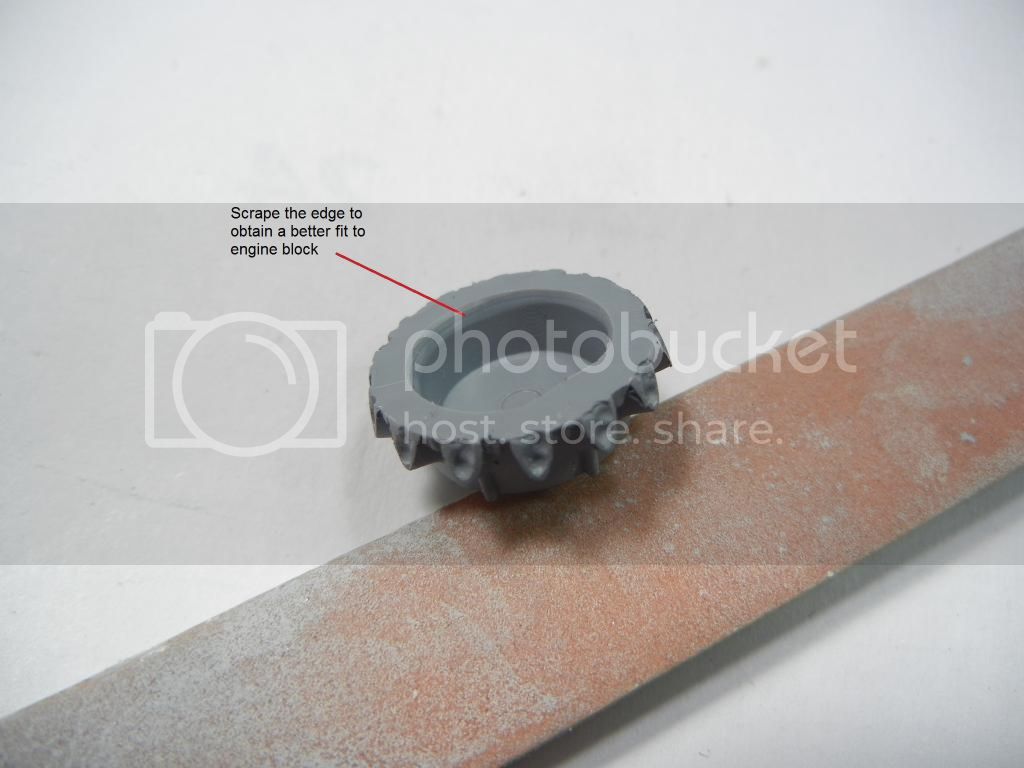
Working more on the engine, I noticed the front part of the engine (I'll edit when I get home and can get the part number from the kit instructions) did not want to fit well. I scraped around the inside mating surface and the part fit well:


Front of engine. Just needs the pushrods attached at this point:


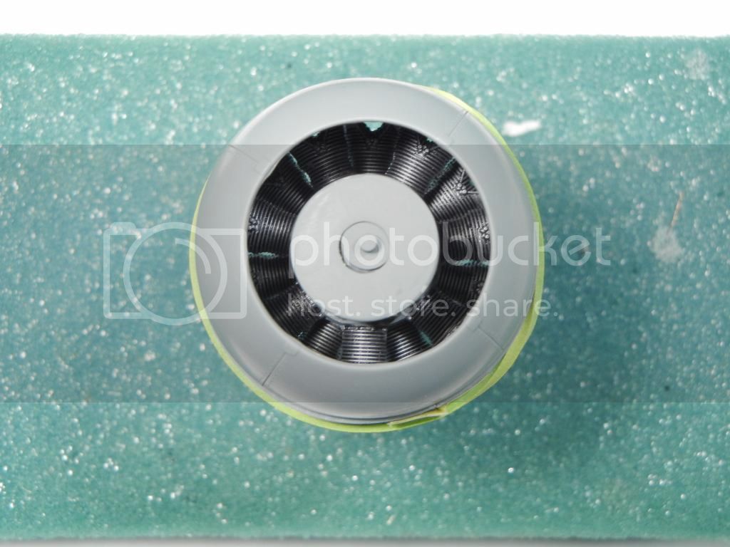
There is not too much visible in the cowl when assembled as can be seen in this test fit (note this pic is taken trying to see as much as possible):


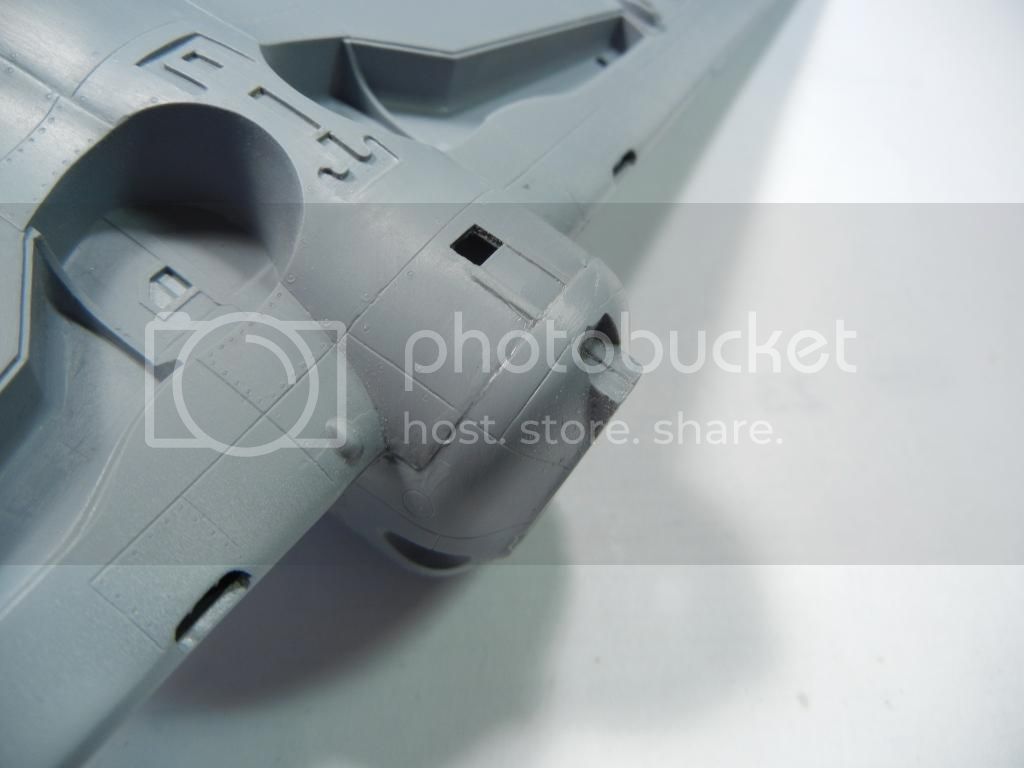
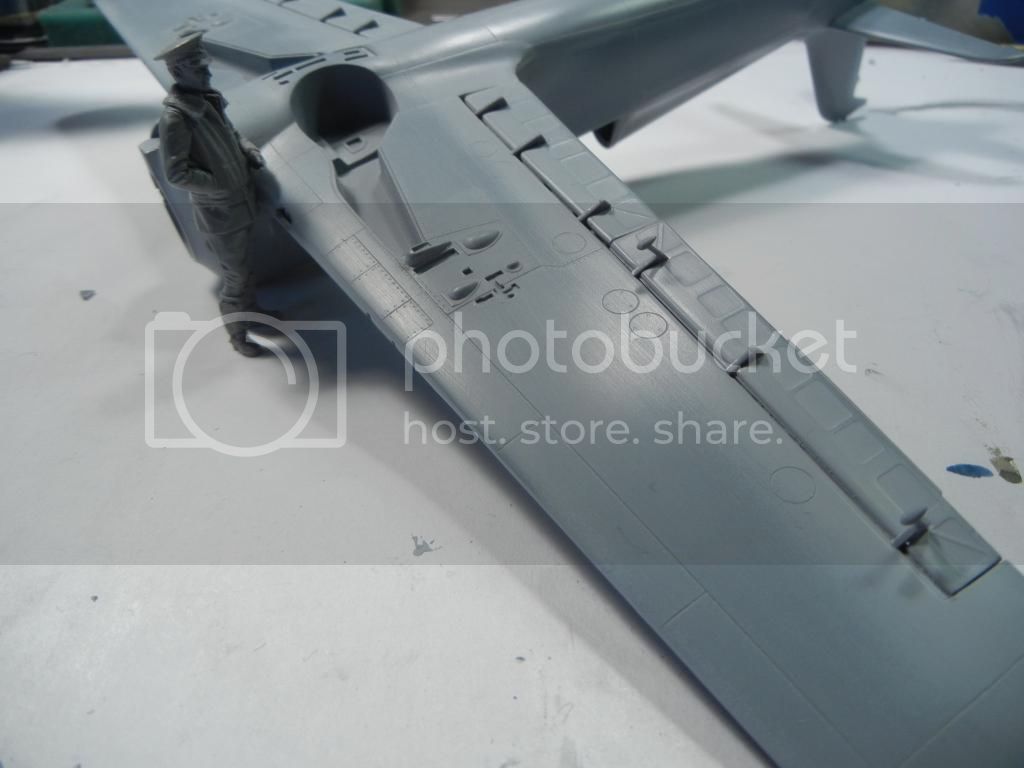
I also managed to get the wings attached. I decided to leave off the control surfaces until afterwards. My example had a little fit trouble on the bottom, but I tried to minimize this by putting the gaps where they would be easiest to deal with.

Bottom rear will need a little filler:


Bottom front will need a little sanding:


Wing roots fit great:


Overall not bad for a limited-run kit. Admittedly I was in a bit of a hurry when I attached the wings and may have been able to get an even better fit with a bit more pre-work and perhaps some shims. I still think it won't be too difficult to sort out even as it is.

That's all for now - thanks for looking!

Doug

Joel_W
Staff MemberAssociate Editor
AUTOMODELER
_VISITCOMMUNITY
New York, United States
Joined: December 04, 2010
KitMaker: 11,666 posts
AeroScale: 7,410 posts
Posted: Tuesday, September 23, 2014 - 04:11 AM UTC
Doug,
About the only fit issues that will really need work is the cowl/lower wing joint. But it's nothing that you can't handle.
Joel
DougN1
_VISITCOMMUNITY
Georgia, United States
Joined: August 08, 2011
KitMaker: 410 posts
AeroScale: 409 posts
Posted: Wednesday, October 22, 2014 - 01:43 AM UTC
After traveling for a few weeks, it's time for an update.

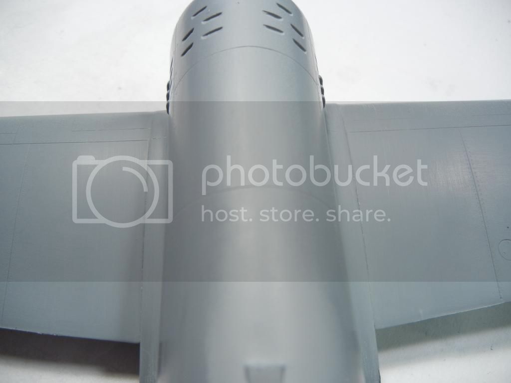
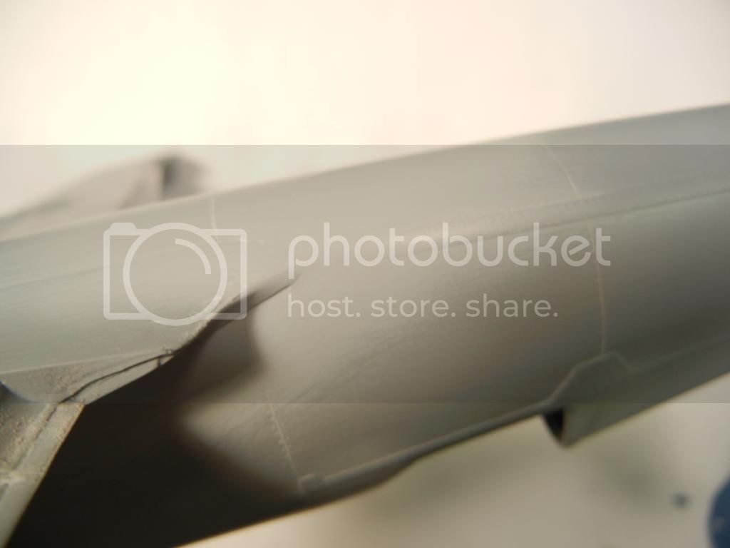
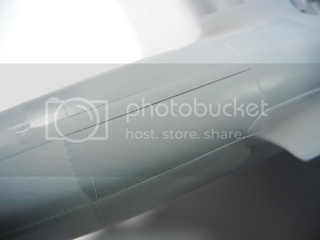
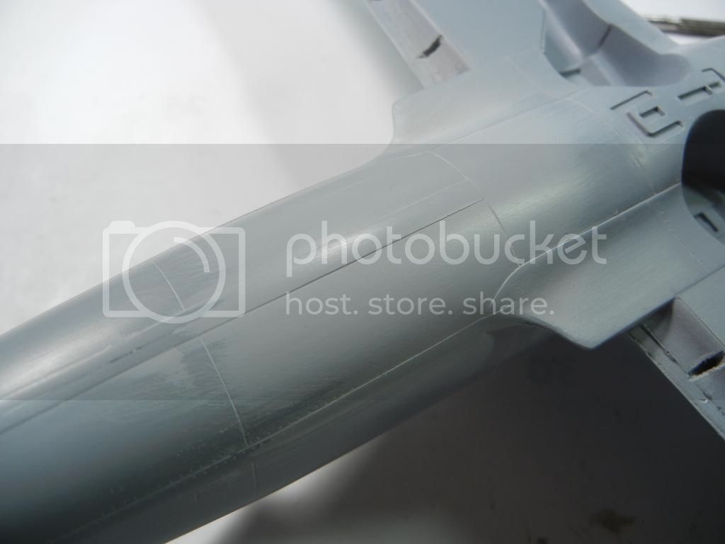
After letting everything get set, I took a sanding stick to the wing/fuselage join and smoothed it out:


Not bad at all! In the photo above, I scribed the join line, thinking that a panel like was supposed to be there, but that was not the case so I filled the scribe line with Mr Surfacer.

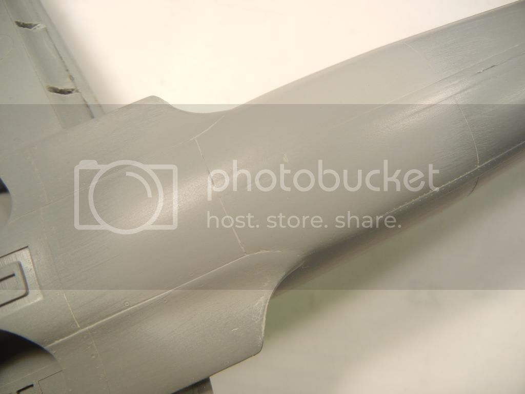
After a spray of Mr Surfacer primer, things look pretty good:


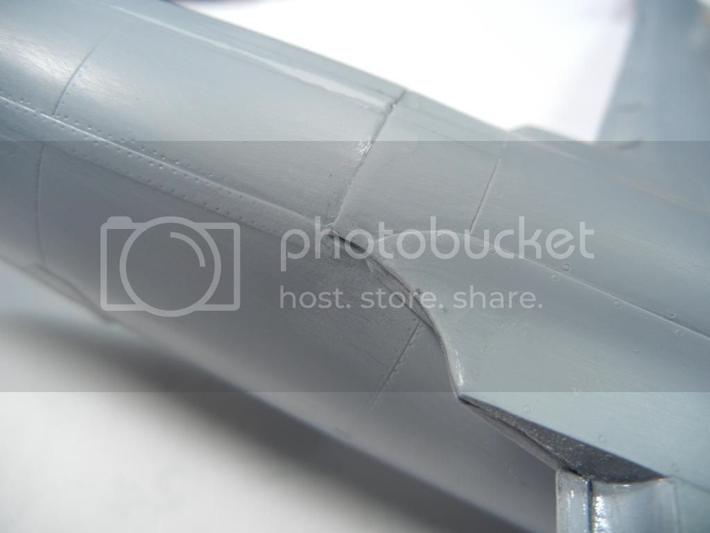
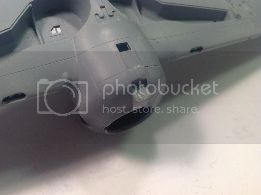
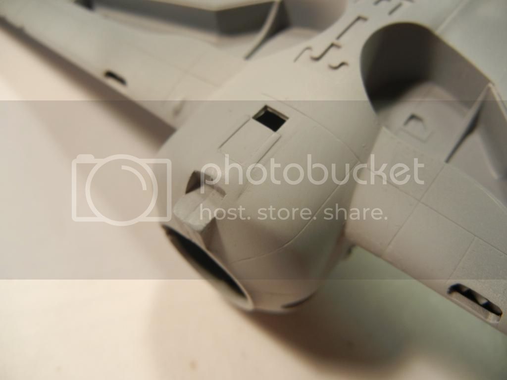
However, the detail of the three reinforcing strips was lost near the join:


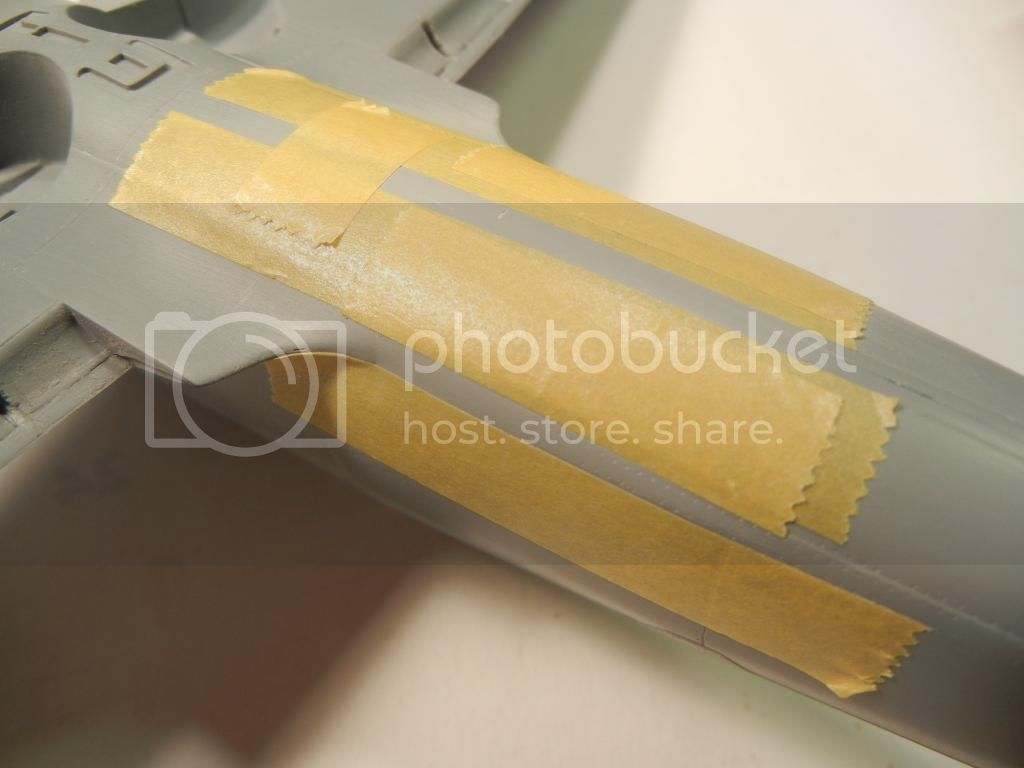
But, this is an easy fix, again, using Mr Surfacer. Simply mask off the area that should be a raised panel (or reinforcing strip in this case)


Then spray a light coat of Mr Surfacer to "seal" the tape edges, and then spray a heavy coat on until you fill the area in question about level with the tape


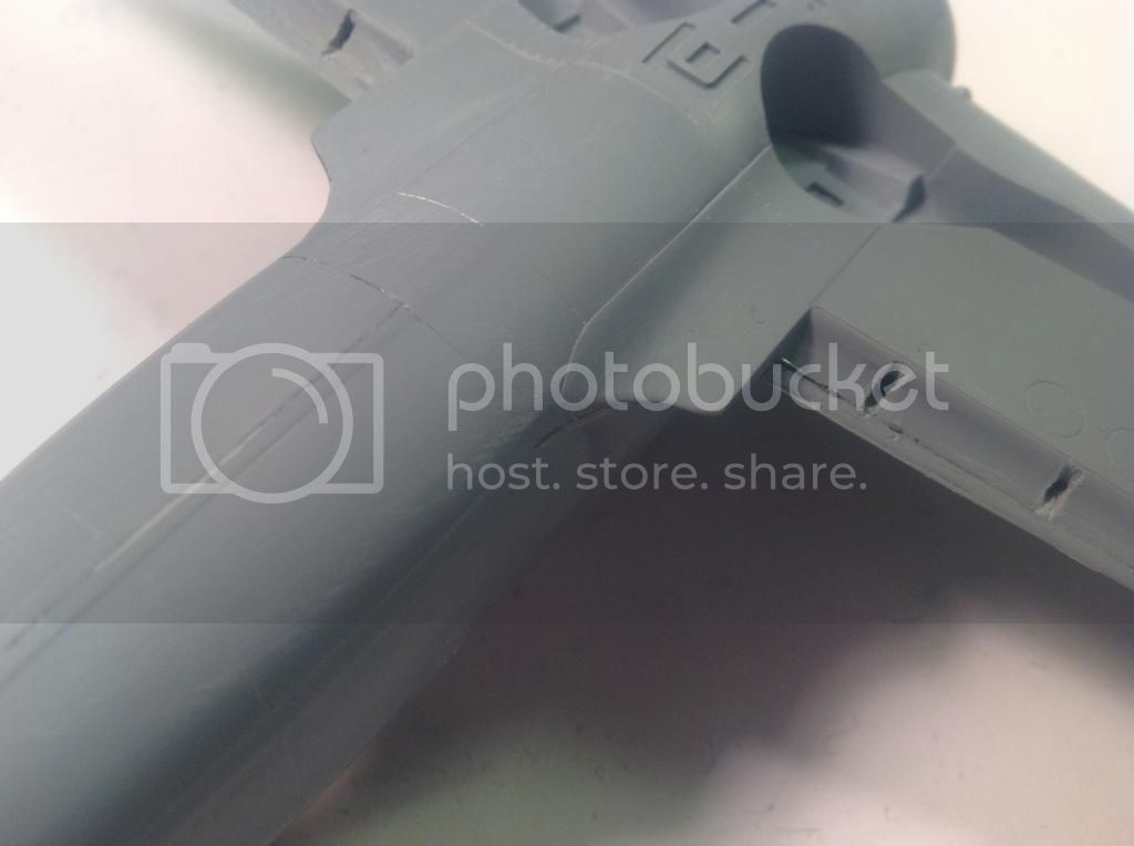
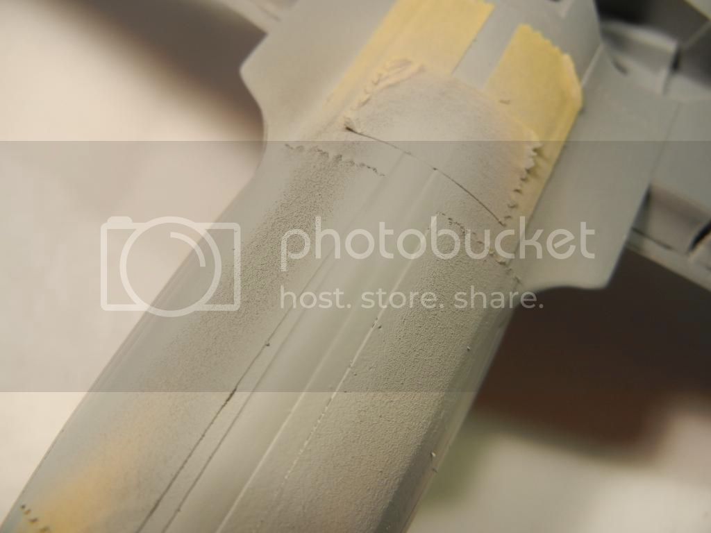
I left this to dry for about 24 hours and then carefully removed the tape (by pulling away at an angle) and got this


I then sanded it down to match the height of the original raised area (reinforcing strip) and buffed it with some 0000 steel wool to finish it off


Thats all for this update. I'm working on getting the engine finished up as well as getting the remaining bits attached to the airframe next.

Thanks for looking, comments/questions/critique always welcomed!

Doug
Joel_W
Staff MemberAssociate Editor
AUTOMODELER
_VISITCOMMUNITY
New York, United States
Joined: December 04, 2010
KitMaker: 11,666 posts
AeroScale: 7,410 posts
Posted: Wednesday, October 22, 2014 - 02:24 AM UTC
Doug,
Your method for that raised panel is something in a million years I never would have thought of. I just added a raised panel on my P-38L build. I started by gluing down the panel made from .040 sheet, then sanded till it was paper thin.

My only concern with your paint method is that it could be more prone to chips, nicks, and scratches being paint.

Joel
DougN1
_VISITCOMMUNITY
Georgia, United States
Joined: August 08, 2011
KitMaker: 410 posts
AeroScale: 409 posts
Posted: Thursday, October 23, 2014 - 05:41 AM UTC
Thanks Joel The Mr. Surfacer dries pretty hard, so it's not as fragile as some paints. I've been using this method to repair/create raised panels for years now and never had any chipping/damage problems.

Thanks,

Doug
Joel_W
Staff MemberAssociate Editor
AUTOMODELER
_VISITCOMMUNITY
New York, United States
Joined: December 04, 2010
KitMaker: 11,666 posts
AeroScale: 7,410 posts
Posted: Thursday, October 23, 2014 - 06:44 AM UTC

Quoted Text

Thanks Joel The Mr. Surfacer dries pretty hard, so it's not as fragile as some paints. I've been using this method to repair/create raised panels for years now and never had any chipping/damage problems.

Thanks,

Doug


Doug,
It sure could solve a lot of small issues I always seem to run in to.
Joel
Merlin
Staff MemberSenior Editor
AEROSCALE
#017
_VISITCOMMUNITY
United Kingdom
Joined: June 11, 2003
KitMaker: 17,582 posts
AeroScale: 12,795 posts
Posted: Thursday, October 23, 2014 - 08:18 AM UTC
Nice going Doug!

The sprayed Mr Surfacer technique is something I really must try, but I've always been wary of wrecking my airbrush. How do you thin it to spray it safely?

All the best

Rowan
Joel_W
Staff MemberAssociate Editor
AUTOMODELER
_VISITCOMMUNITY
New York, United States
Joined: December 04, 2010
KitMaker: 11,666 posts
AeroScale: 7,410 posts
Posted: Thursday, October 23, 2014 - 09:58 AM UTC
Rowan,
I only have Mr. Surfacer 1,000, and I thin it 1:1 with Tamiya Yellow Cap Lacquer Thinner. Airbrushes just fine. For the 500 I would thin it 2:3 for starters. I never had any issues cleaning my air brush with LC afterwards. I also airbrush Tamiya Gray Surface primer 1:1 without any issues.
Joel
DougN1
_VISITCOMMUNITY
Georgia, United States
Joined: August 08, 2011
KitMaker: 410 posts
AeroScale: 409 posts
Posted: Friday, October 24, 2014 - 03:53 AM UTC
I use the 1200, thinned with Mr Color Leveling thinner, or just plain lacquer thinner about 50% for spraying. No problems spraying it. If you get spider webs or pebbling, it means you need more thinner. I use a Paasche H with a #1 tip to spray it. No issues after many years

I use the 500 only with a brush

Doug
Joel_W
Staff MemberAssociate Editor
AUTOMODELER
_VISITCOMMUNITY
New York, United States
Joined: December 04, 2010
KitMaker: 11,666 posts
AeroScale: 7,410 posts
Posted: Friday, October 24, 2014 - 04:49 AM UTC

Quoted Text

I use the 1200, thinned with Mr Color Leveling thinner, or just plain lacquer thinner about 50% for spraying. No problems spraying it. If you get spider webs or pebbling, it means you need more thinner. I use a Paasche H with a #1 tip to spray it. No issues after many years

I use the 500 only with a brush

Doug


Doug,
The fact that you use a #1 needle/cone on your Paasche gun is very interesting to me. I've used that model gun for more then 40 years (I've replaced the airbrush a few times during that time period), and my go to setup is the #3. I only use the #1 for fine detail work. Do you use the #1 as your main setup?
Joel
Holdfast
Staff MemberPresident
IPMS-UK KITMAKER BRANCH
#056
_VISITCOMMUNITY
England - South West, United Kingdom
Joined: September 30, 2002
KitMaker: 8,581 posts
AeroScale: 4,913 posts
Posted: Friday, October 24, 2014 - 07:17 PM UTC
Nice, interesting and informative updates Doug. I've read about using primer to build up surface detail in a book about scratch building, nice to actually see it in action
DougN1
_VISITCOMMUNITY
Georgia, United States
Joined: August 08, 2011
KitMaker: 410 posts
AeroScale: 409 posts
Posted: Friday, December 19, 2014 - 10:31 PM UTC
Guess it's time for an update

@ Joel, yes I use the #1 tip as my main setup with the Paasche H. I can get wide area coverage, as well as pretty good lines with it. I do use the #3 tip for clearcoats however I use my H&S Infinity for detail work like getting a tight edge between colors, mottling, touchups, etc.

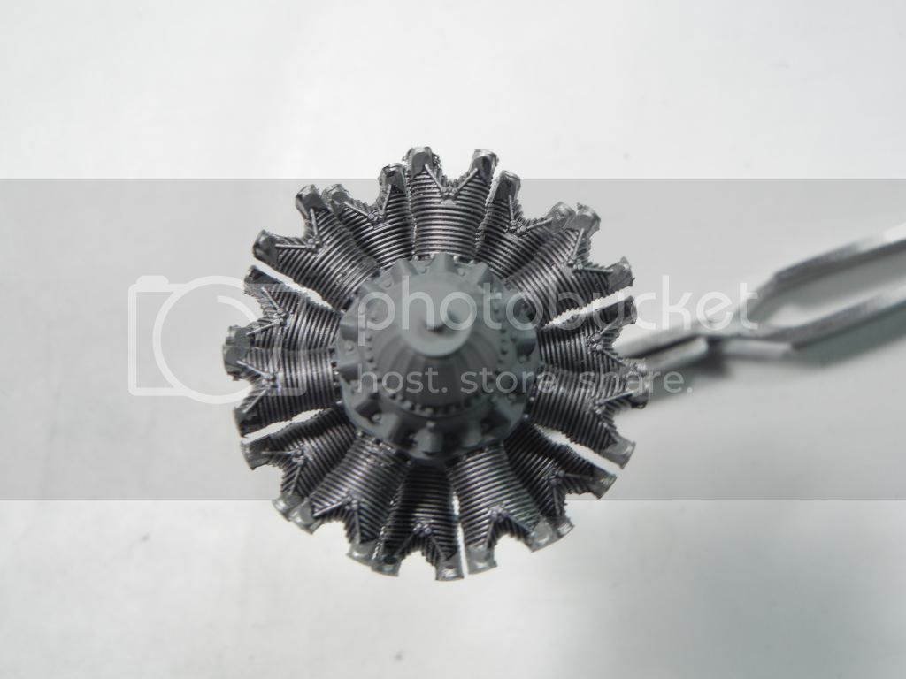
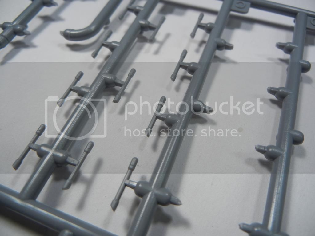
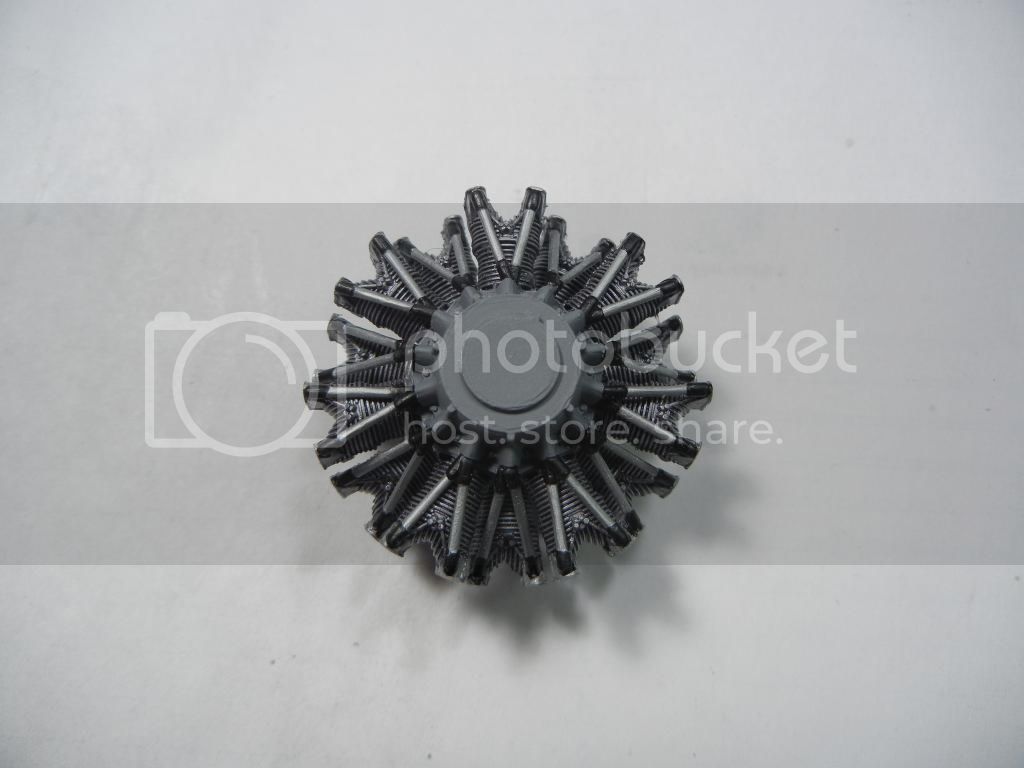
I got most of the engine completed. The pushrods on the front took some time to complete, as there are 28 of them and for some reason FRROM decided to put the sprue attachment points on the front-facing part of the pushrod, creating a lot of cleanup work.


I started with the rear cylinder bank pushrods, they attach with one over the other at the crankcase like so:


Eventually, I got them all attached and painted. I think the end result looks quite good:


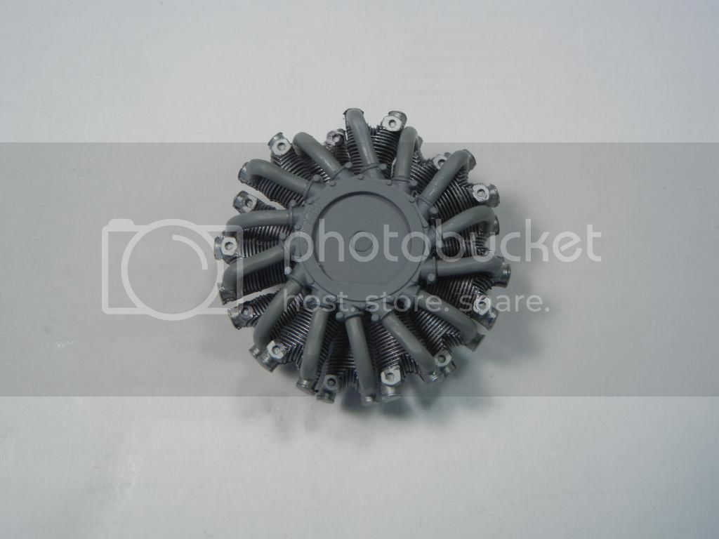
I also attached the intake pipes to the rear of the engine, these were much easier as FRROM wisely put the sprue attachment points in a better spot. Although the instructions would have you paint them a "burnt metal" color, I painted them grey as these pipes just carry air to the engine, not hot exhaust.


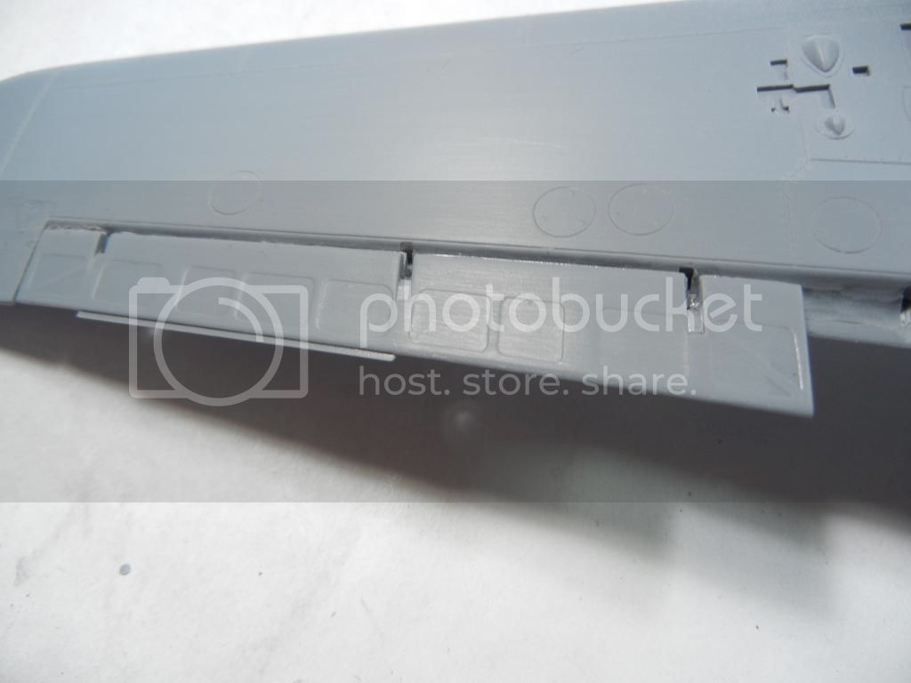
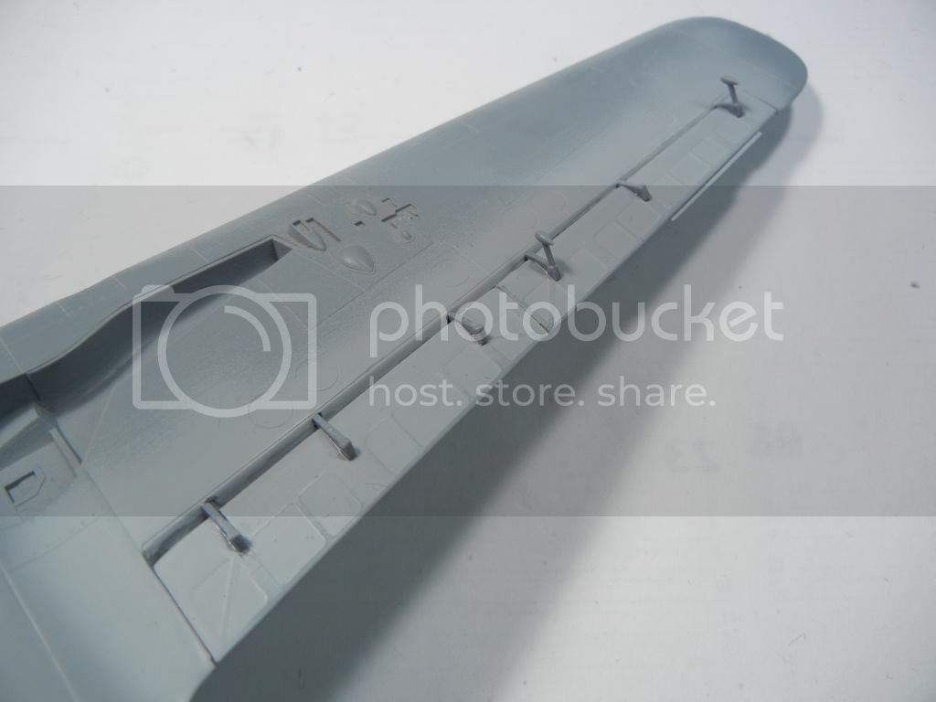
Another area I needed to think about was the control surfaces. In the end I decided to have the flaps up, and once I decided that I had to figure out the easiest way to get them in place. The kit instructions would have you attach the actuators to the wing, and then attach the flaps and ailerons to the actuators. Unfortunately, test fitting on my kit (maybe due to user error) the slots for the actuators in the wing did not quite line up right to the slots on the control surfaces, which would have created some fit issues.


So, I decided to just glue the ailerons and flaps directly to the wing, and then trimmed the bottom off the acuators and attached them in place once the glue had dried, which seemed to work well for me


If you want to improve the look of your kit, you can also drill out the lightening holes in the actuators. I didn't do that for this kit, but will try it on my next one. Also note that if you put the flaps down, the ailerons also both drop a few degrees (like a 109), so you'll need to replicate that as well.

I'll be working on getting the final bits on the airframe that need to go on before I can start painting now that I've decided on a scheme, as well as getting the exhausts on the engine.

Thanks for looking, comments/questions/critique always welcomed!

Doug

chukw1
_VISITCOMMUNITY
California, United States
Joined: November 28, 2007
KitMaker: 817 posts
AeroScale: 729 posts
Posted: Friday, December 19, 2014 - 10:53 PM UTC
Very nice, Doug! Your fix on those reinforcement plates is simply splendid. The ailerons did sync with the flaps only up to airframe #75- afterwards that linkage was removed so the flaps could be used as dive brakes. Thanks to Radu's excellent books I think we're becoming veritable fonts of trivia on this airframe!
Holdfast
Staff MemberPresident
IPMS-UK KITMAKER BRANCH
#056
_VISITCOMMUNITY
England - South West, United Kingdom
Joined: September 30, 2002
KitMaker: 8,581 posts
AeroScale: 4,913 posts
Posted: Saturday, December 20, 2014 - 12:16 PM UTC
Nicely done Doug, I'm really looking forward to seeing some paint on the is