Doug,
The engine is really starting to look quite good. Excellent point on why not to follow the kit painting recommendations on color for those intake pipes. Proper research really does come into play throughout the build.
Since this is a 1/32 scale build, wouldn't there be a visible spacing between the ailerons & flaps and the corresponding wing surface? Mounting them with steel wire would have helped to create that gap. The actuator fix really came out quite well.
Joel
World War II
Discuss WWII and the era directly before and after the war from 1935-1949.
Discuss WWII and the era directly before and after the war from 1935-1949.
Hosted by Rowan Baylis
FRROM 1/32 IAR-81C Build Review
Joel_W

Joined: December 04, 2010
KitMaker: 11,666 posts
AeroScale: 7,410 posts

Posted: Saturday, December 20, 2014 - 07:36 PM UTC
paulbica

Joined: November 12, 2010
KitMaker: 10 posts
AeroScale: 9 posts
Posted: Monday, December 22, 2014 - 11:00 PM UTC
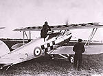
Hi Doug, your model looks great. I am anxious to start mine. I have one comment regarding the control column. I think that for IAR 81 C should be used the D28 piece from the kit instead of D11.
DougN1

Joined: August 08, 2011
KitMaker: 410 posts
AeroScale: 409 posts

Posted: Monday, December 29, 2014 - 12:44 AM UTC
Thanks everyone!
@ Chuck - your right, sloppy "research" on my part! I was going through the book looking for information on something else and saw that captioned on one of the photos and didn't read the text to get the clarification. Thanks so much for correcting my statement about the ailerons/flaps as I don't want to have bad info out there for future builders!
@ Joel - I agree, pinning the control surfaces may have been a better way to go, but in the end these turned out ok. I'll remember that for the next one (which will get done one of these days)
@ Paul - I believe you are correct about the control column. In Radu's second book (which I did not have when I built the cockpit) there is additional information on the control column options. It seems this particular one was for IAR-80/81's with 6 guns, whereas the "spade grip" was used starting with airframe #181.
Again, thanks to all for looking in, and for providing good information and suggestions!
Thanks!
Doug

DougN1

Joined: August 08, 2011
KitMaker: 410 posts
AeroScale: 409 posts

Posted: Sunday, January 04, 2015 - 10:48 PM UTC
I managed to get some more done on this model so it's time for another update!
I managed to finish up all the things I wanted to get done in order to get the airframe ready for paint.
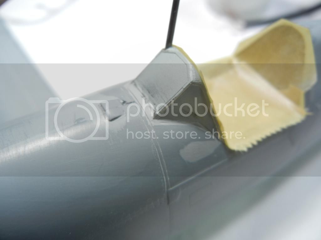
Starting with the tail, the instructions tell you to add the post on the vertical stabilizer for the aerial mast (0.7mm diameter/3mm tall). There is a "nub" on the kit where the post goes, but it's a bit oversize, so I just used it as an indicator for where to drill the hole for the wire I used.
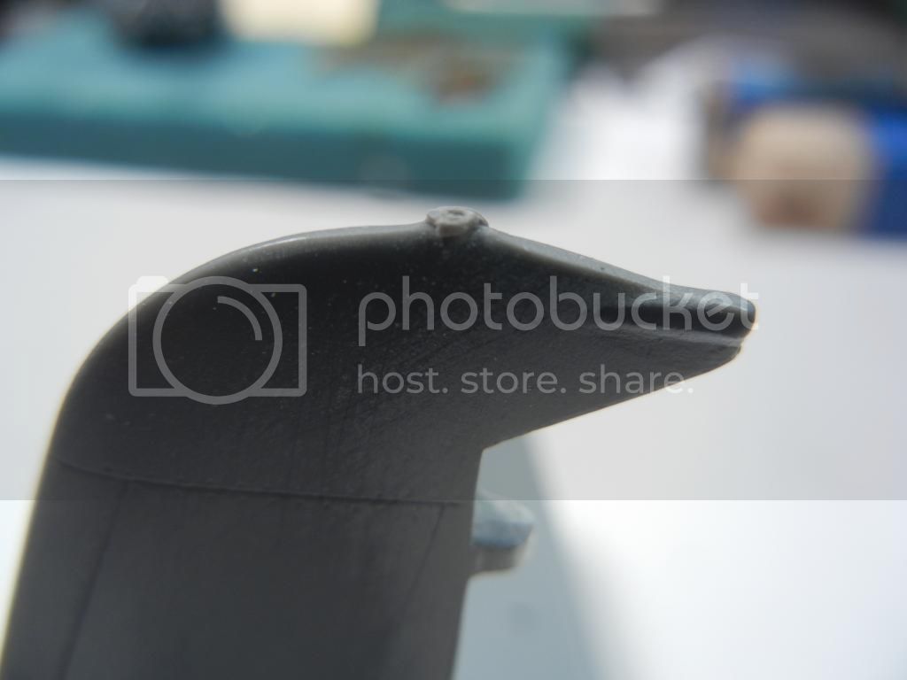
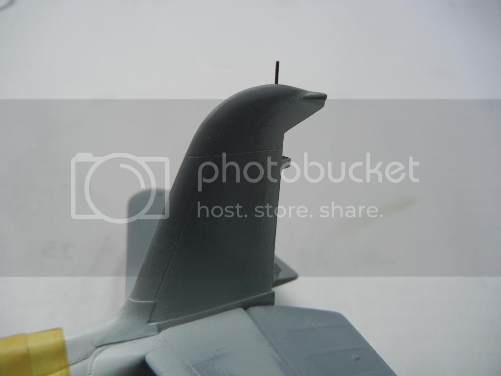
I then sanded off the "nub" and used some .20 wire for the post as anything larger did not look right. I placed the wire 3mm high, but again, looking at photos, it seems a bit tall, so I'll probably cut 1mm or so off.
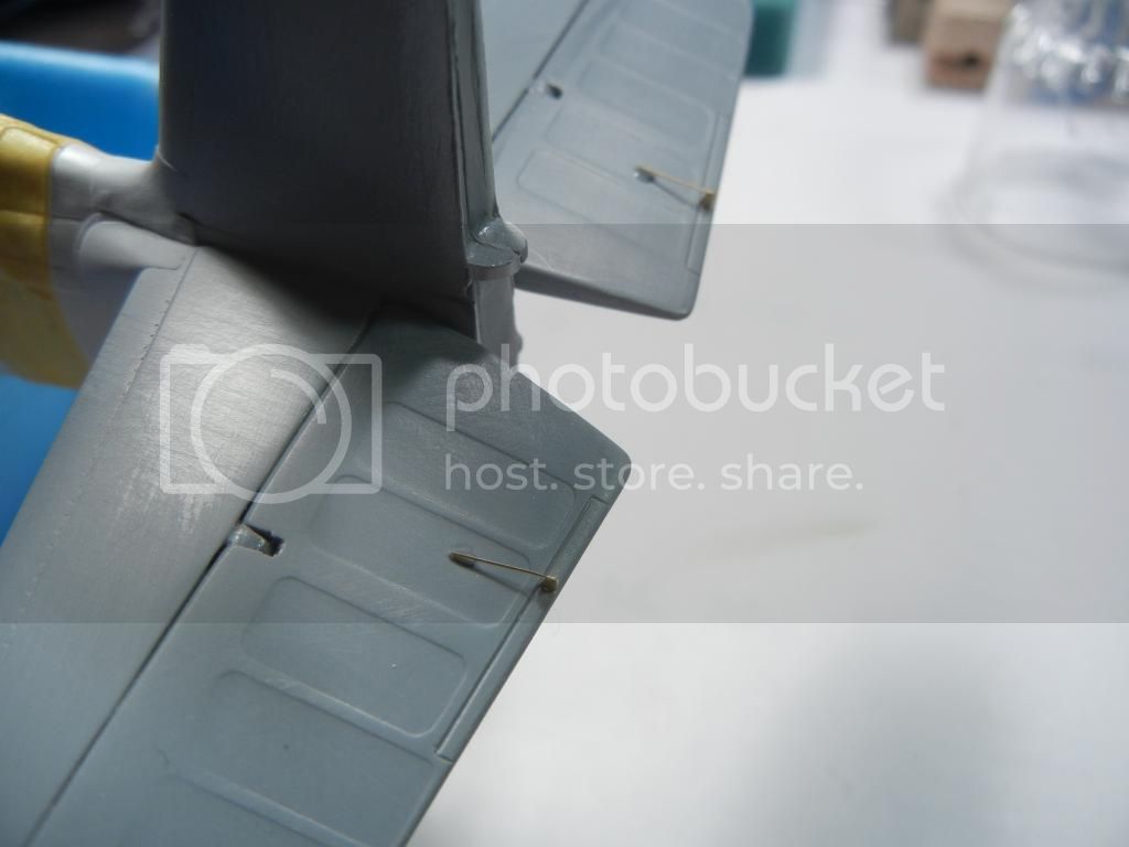
I also decided to add the PE elevator trim tab actuators (top and bottom) at this time. The "wire" part of the PE is a bit long as it covers the fairings in the elevator as well. While the "best practice" would be to drill a hole in the fairings for the "wire" bit, I opted for the lazy method and just sanded the fairings a bit and put a drop of superglue on top of the "wire" to replicate the fairing.
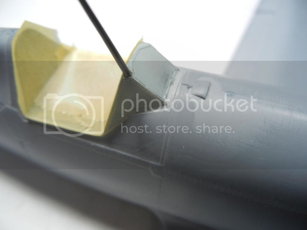
Moving forward, I also attached the windscreen to the fuselage. Before you can do that, you need to drill out a hole for the aerial mast. The mast also needs to go though from the inside as it is tapered. I painted the mast in the exterior color (as indicated by photos) before installing it. Fit of the windscreen was excellent, and I just ran a small bead of Mr. Surfacer around the join (and sanded it) to fair it in.
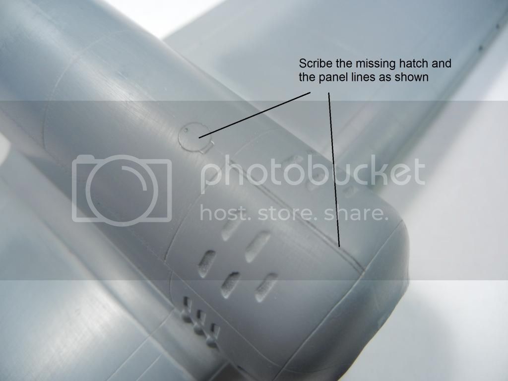
I also scribed the missing filler hatch and panel lines on the nose (as shown in the pic):
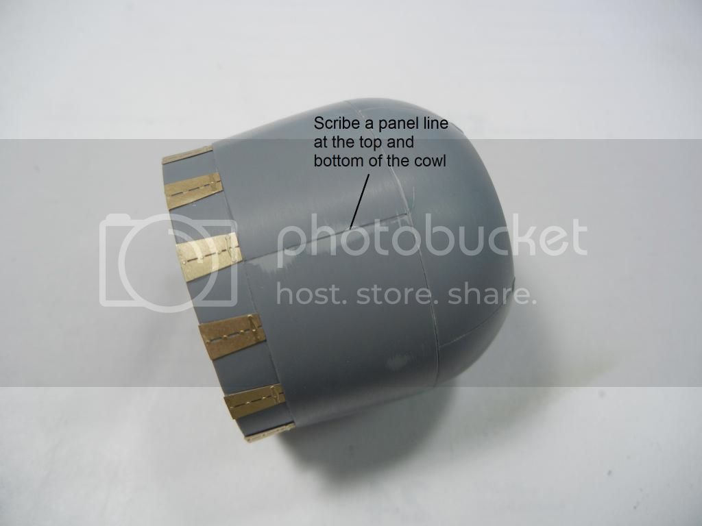
I also assembled the 3 part cowl, and while fit was not great, a little sanding sorted everything out great. I attached the PE cooling flaps and scribed the panel lines on the top and bottom as needed.
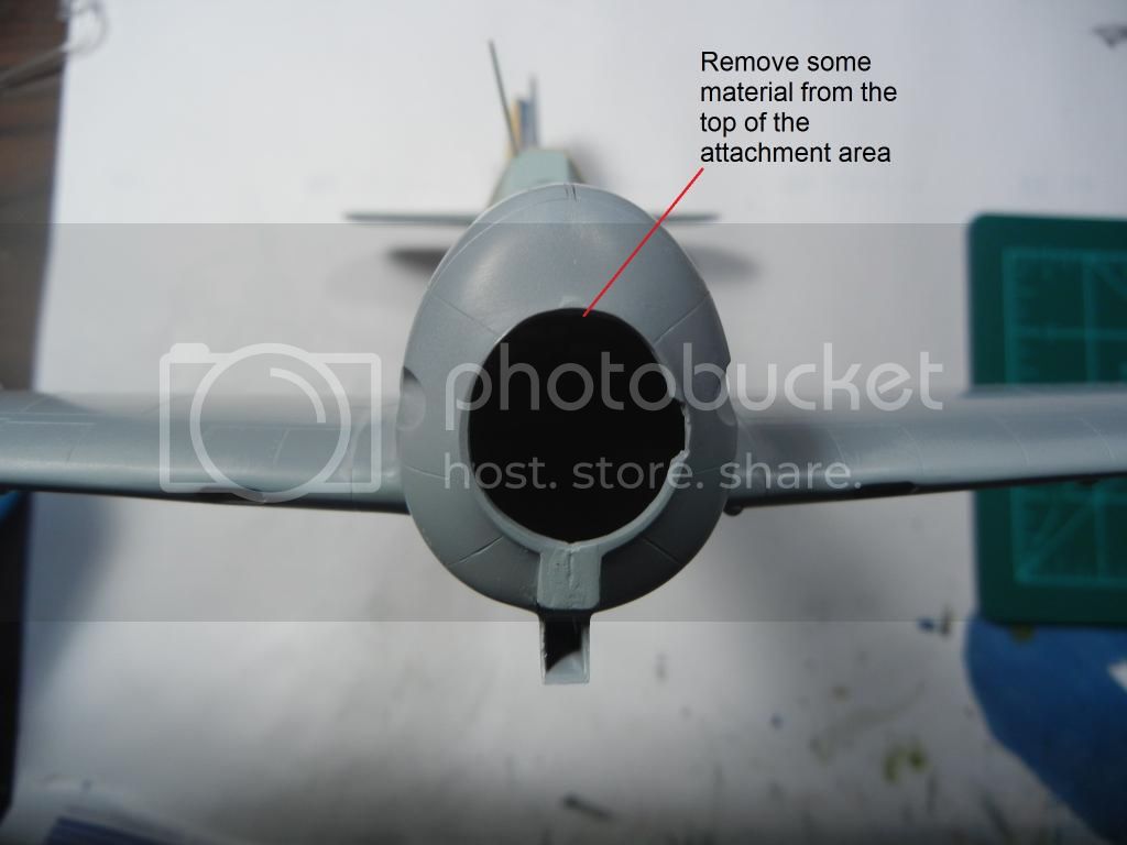
I decided to try to test-fit the engine, cowl and airframe together to see how it looked. Unfortunately, it takes 3 hands to do that, so no pics. But, I did notice that the engine/cowl seemed to sit a bit low. So, I enlarged the top of the attachment area on the fuselage so that I could adjust as needed when it came time to glue everything in place.
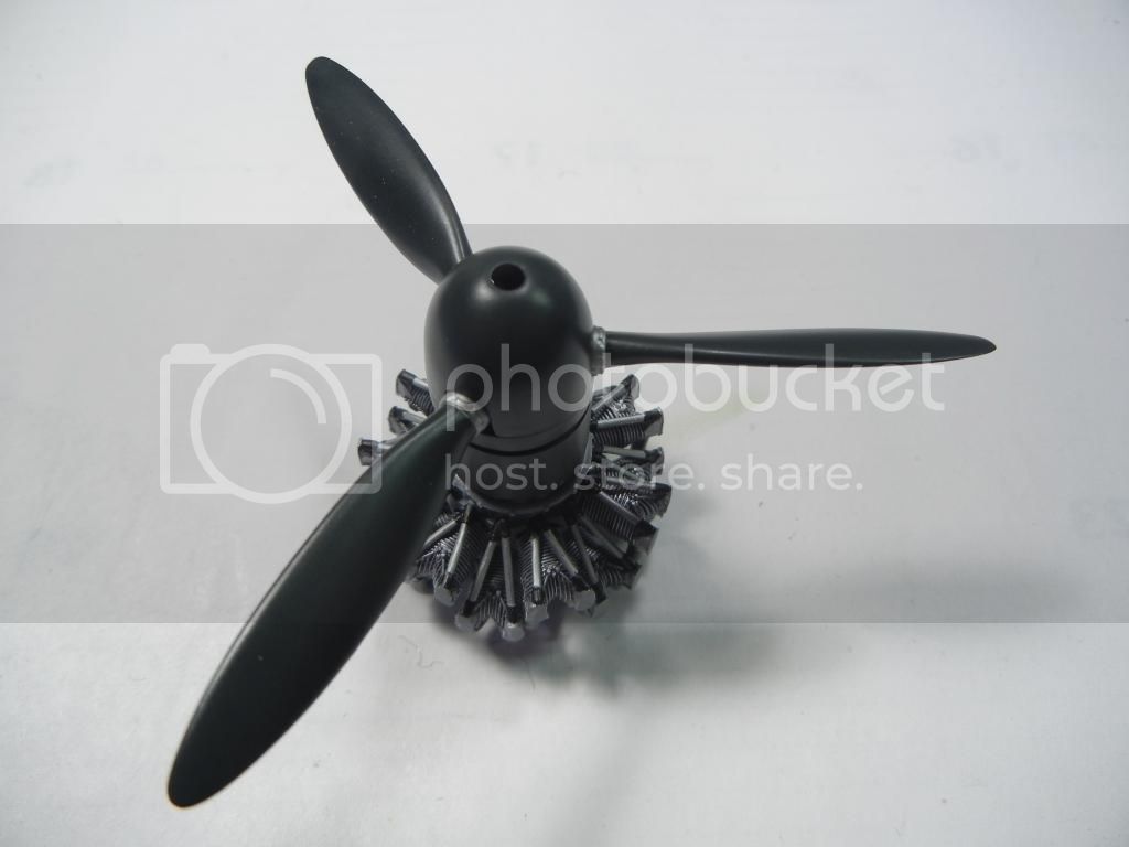
I also built and painted the prop. Here it is stuck on the almost completed engine:
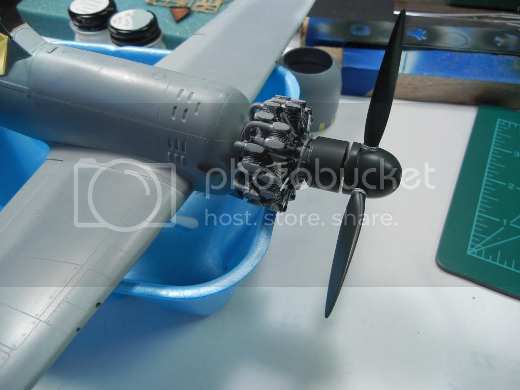
I also managed to get a pic of the engine/prop loosely test fit to the fuselage. Really seems to stick out far because of the cylinder that is behind the prop (that covers the front of the engine)
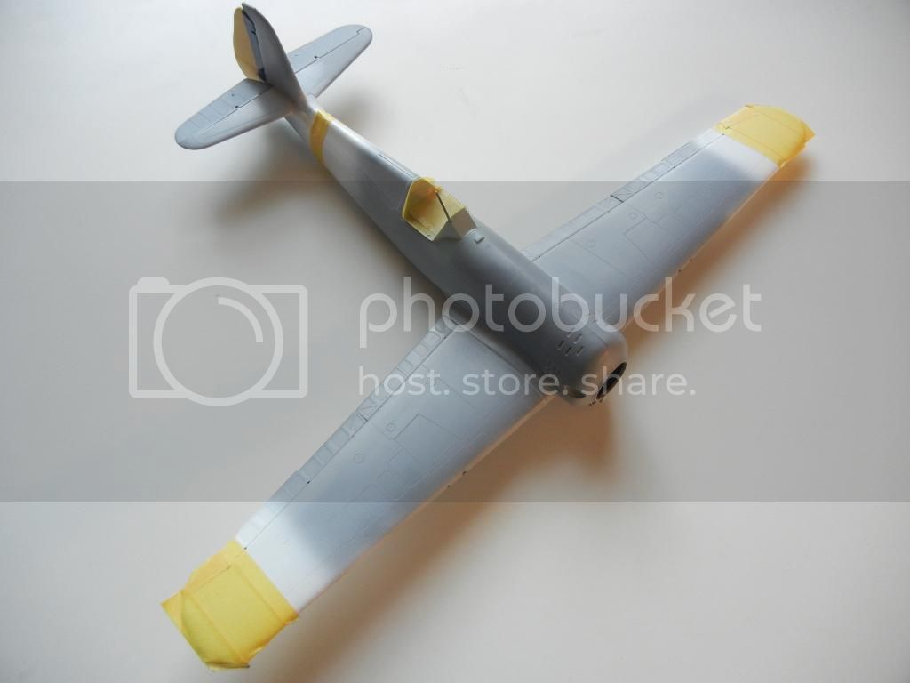
So, now we are ready for paint!
Thanks for looking, comments/questions/critique always welcomed!
Doug
I managed to finish up all the things I wanted to get done in order to get the airframe ready for paint.
Starting with the tail, the instructions tell you to add the post on the vertical stabilizer for the aerial mast (0.7mm diameter/3mm tall). There is a "nub" on the kit where the post goes, but it's a bit oversize, so I just used it as an indicator for where to drill the hole for the wire I used.

I then sanded off the "nub" and used some .20 wire for the post as anything larger did not look right. I placed the wire 3mm high, but again, looking at photos, it seems a bit tall, so I'll probably cut 1mm or so off.

I also decided to add the PE elevator trim tab actuators (top and bottom) at this time. The "wire" part of the PE is a bit long as it covers the fairings in the elevator as well. While the "best practice" would be to drill a hole in the fairings for the "wire" bit, I opted for the lazy method and just sanded the fairings a bit and put a drop of superglue on top of the "wire" to replicate the fairing.

Moving forward, I also attached the windscreen to the fuselage. Before you can do that, you need to drill out a hole for the aerial mast. The mast also needs to go though from the inside as it is tapered. I painted the mast in the exterior color (as indicated by photos) before installing it. Fit of the windscreen was excellent, and I just ran a small bead of Mr. Surfacer around the join (and sanded it) to fair it in.


I also scribed the missing filler hatch and panel lines on the nose (as shown in the pic):

I also assembled the 3 part cowl, and while fit was not great, a little sanding sorted everything out great. I attached the PE cooling flaps and scribed the panel lines on the top and bottom as needed.

I decided to try to test-fit the engine, cowl and airframe together to see how it looked. Unfortunately, it takes 3 hands to do that, so no pics. But, I did notice that the engine/cowl seemed to sit a bit low. So, I enlarged the top of the attachment area on the fuselage so that I could adjust as needed when it came time to glue everything in place.

I also built and painted the prop. Here it is stuck on the almost completed engine:

I also managed to get a pic of the engine/prop loosely test fit to the fuselage. Really seems to stick out far because of the cylinder that is behind the prop (that covers the front of the engine)

So, now we are ready for paint!

Thanks for looking, comments/questions/critique always welcomed!
Doug
Joel_W

Joined: December 04, 2010
KitMaker: 11,666 posts
AeroScale: 7,410 posts

Posted: Monday, January 05, 2015 - 12:52 AM UTC
Doug
Looking forward to seeing some paint on it. The engine-space-prop does really look weird. Did you test fit it with the cowl in place?
Joel
Looking forward to seeing some paint on it. The engine-space-prop does really look weird. Did you test fit it with the cowl in place?
Joel
Posted: Monday, January 05, 2015 - 10:59 AM UTC
Looking good Doug 
Yes that engine to spinner tip length does look a bit over long but, as Joel says, what does it look like with the cowling in place?

Yes that engine to spinner tip length does look a bit over long but, as Joel says, what does it look like with the cowling in place?

DougN1

Joined: August 08, 2011
KitMaker: 410 posts
AeroScale: 409 posts

Posted: Thursday, January 08, 2015 - 11:58 PM UTC
Thanks for your comments guys 
The cowl covers everything perfectly, as on the real thing the rear of the cowl is not right against the fuselage, so no worries. Since the fit between the engine and cowl is very tight, I don't want to keep cramming them together lest I break something, so no photos yet
My laziness with the elevator trim tab actuators ended up causing me more work (as usually happens). I should have consulted my references before doing anything, as it would have shown me that on the real aircraft, there is hardly any fairing at all (if there even is one). So, the best thing to do would have been to reduce the fairing to a tiny bump, and then attach the PE part. However, I discovered this after I built up a sizeable, but not good looking fairing with superglue and Mr Surfacer (which was way more work than the original "best practice" above of drilling a hole into the fairing and sticking the end of the PE cable in). Only after all that unsuccessful work did I decide it was time to consult my references to see what it actually should look like
So, I ended up removing my mess, and damaging all the PE parts of course (and even losing 2 of them). Fortunately, I contacted the fine folks at FRROM, who responded within hours, and now I have a new PE fret on the way. I grabbed the PE fret from one of my two other IAR-81 kits and will press onwards.
So, out came the tools and a few sessions later, I have removed all traces of my mess and we now stand ready to add the PE parts at the appropriate time.

I have decided to leave them off until almost final assembly lest I damage them.
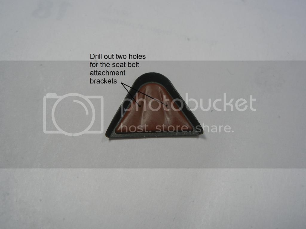
In the interim, I also managed to get the headrest/armor part finished up. Note that you will need to drill some holes in the headrest cushion to attach the seatbelts if you plan to use an attachment point like the real thing. I will just loop a small piece of fine wire and put the ends through the hole for my build.
Ok, off to the paint booth to try to get some paint on again!
Thanks for looking, comments/questions/critique always welcome!
Doug

The cowl covers everything perfectly, as on the real thing the rear of the cowl is not right against the fuselage, so no worries. Since the fit between the engine and cowl is very tight, I don't want to keep cramming them together lest I break something, so no photos yet

My laziness with the elevator trim tab actuators ended up causing me more work (as usually happens). I should have consulted my references before doing anything, as it would have shown me that on the real aircraft, there is hardly any fairing at all (if there even is one). So, the best thing to do would have been to reduce the fairing to a tiny bump, and then attach the PE part. However, I discovered this after I built up a sizeable, but not good looking fairing with superglue and Mr Surfacer (which was way more work than the original "best practice" above of drilling a hole into the fairing and sticking the end of the PE cable in). Only after all that unsuccessful work did I decide it was time to consult my references to see what it actually should look like

So, I ended up removing my mess, and damaging all the PE parts of course (and even losing 2 of them). Fortunately, I contacted the fine folks at FRROM, who responded within hours, and now I have a new PE fret on the way. I grabbed the PE fret from one of my two other IAR-81 kits and will press onwards.
So, out came the tools and a few sessions later, I have removed all traces of my mess and we now stand ready to add the PE parts at the appropriate time.

I have decided to leave them off until almost final assembly lest I damage them.
In the interim, I also managed to get the headrest/armor part finished up. Note that you will need to drill some holes in the headrest cushion to attach the seatbelts if you plan to use an attachment point like the real thing. I will just loop a small piece of fine wire and put the ends through the hole for my build.

Ok, off to the paint booth to try to get some paint on again!
Thanks for looking, comments/questions/critique always welcome!
Doug

DougN1

Joined: August 08, 2011
KitMaker: 410 posts
AeroScale: 409 posts

Posted: Friday, January 30, 2015 - 01:03 AM UTC
Short update this time. Decided to do some work on the main gear before I paint the underside.
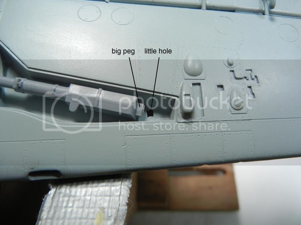
First, I noticed that the "hole" for the gear in the bay is a bit smaller than the "peg" on the gear leg:
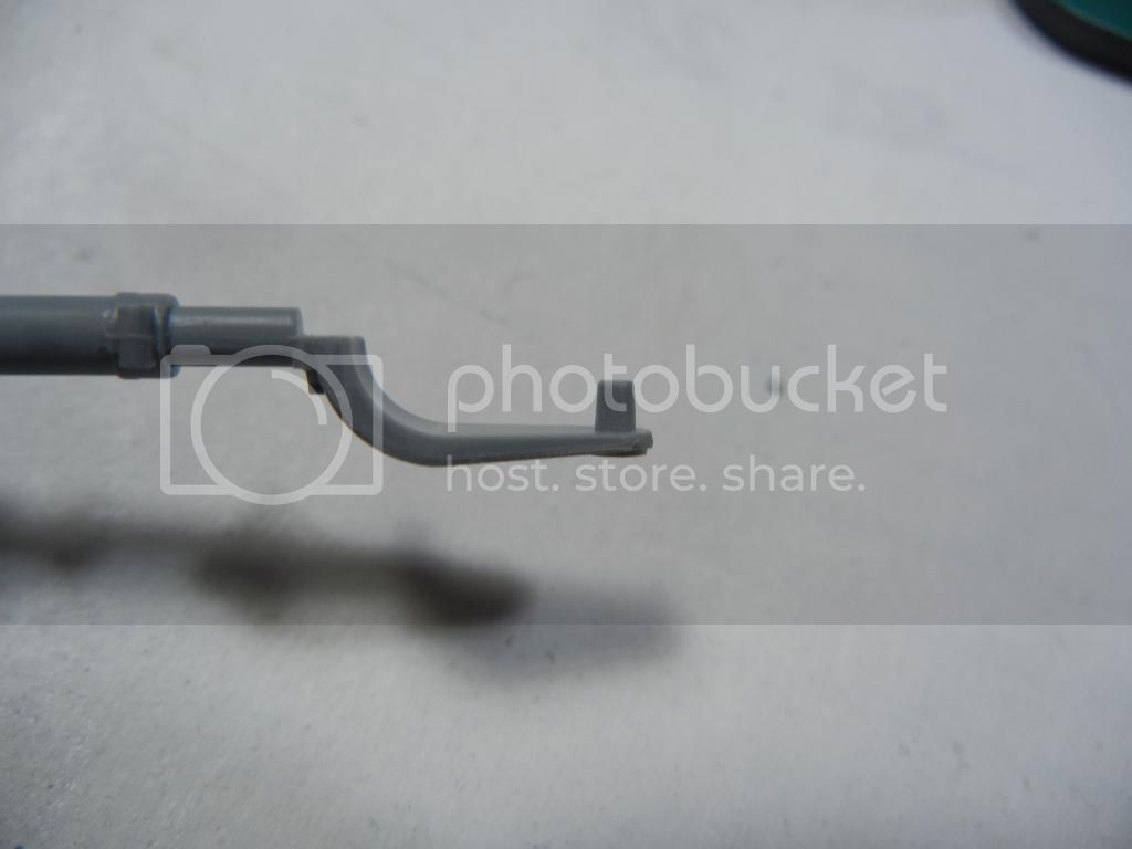
I also noticed that the gear yoke was split into two parts, with a pin on each part to hold the wheel:
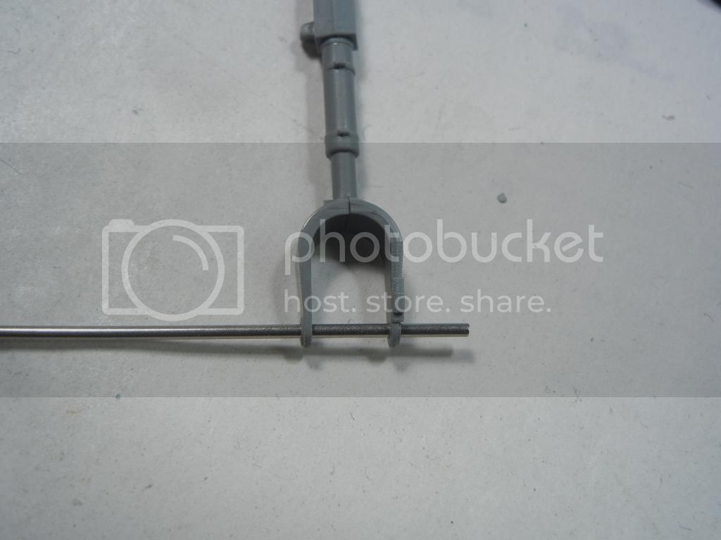
In cases like this, I prefer to remove the pins and insert a piece of rod or tubing to hold the wheel. This allows me to easily clean up any join gaps in the yoke, as well as provides a nice looking, easy way to attach the wheels at the end of the build.
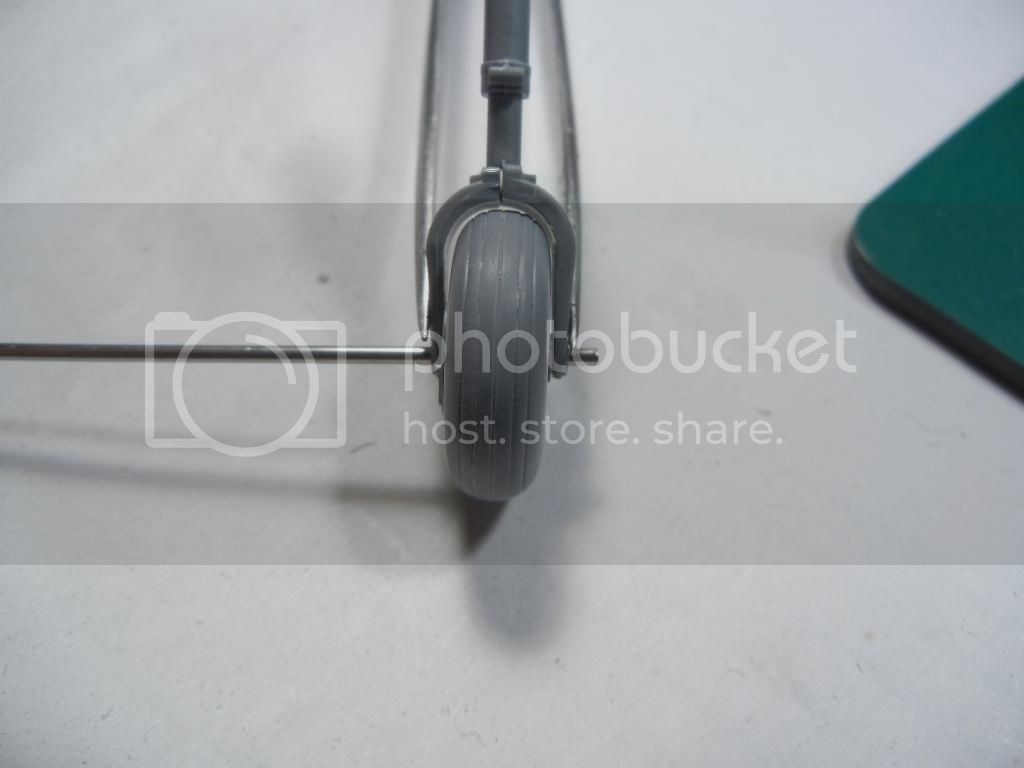
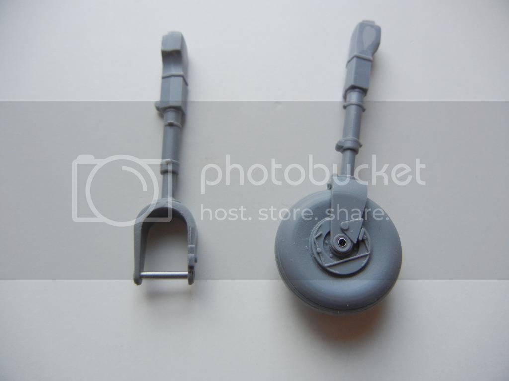

As the gear legs and bay are the same color as the underside, I am planning to attach them and then paint them in place. Now I just need to make and attach the brake lines to each gear leg and get them installed (next update).
Thanks for looking!
Doug
First, I noticed that the "hole" for the gear in the bay is a bit smaller than the "peg" on the gear leg:

I also noticed that the gear yoke was split into two parts, with a pin on each part to hold the wheel:

In cases like this, I prefer to remove the pins and insert a piece of rod or tubing to hold the wheel. This allows me to easily clean up any join gaps in the yoke, as well as provides a nice looking, easy way to attach the wheels at the end of the build.


As the gear legs and bay are the same color as the underside, I am planning to attach them and then paint them in place. Now I just need to make and attach the brake lines to each gear leg and get them installed (next update).
Thanks for looking!
Doug
Joel_W

Joined: December 04, 2010
KitMaker: 11,666 posts
AeroScale: 7,410 posts

Posted: Sunday, February 01, 2015 - 08:26 PM UTC
Doug,
I'm most impressed with your upgrade to the landing gear axles. Adding a cap would represent a bearing cap seal quite nicely.
Are you just going to file open the square hole for the strut or file down the strut peg?
Joel
I'm most impressed with your upgrade to the landing gear axles. Adding a cap would represent a bearing cap seal quite nicely.
Are you just going to file open the square hole for the strut or file down the strut peg?
Joel

DougN1

Joined: August 08, 2011
KitMaker: 410 posts
AeroScale: 409 posts

Posted: Thursday, February 05, 2015 - 07:37 PM UTC
Thanks Joel, I'm actually working it both ways, modifying the strut a little and opening up the hole to be larger 
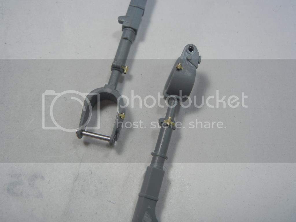
Did a little more work on the gear legs. Unfortunately, the kit doesn't provide any brake lines (common to most kits). Fortunately, Radu's second IAR-80/81 book has some great drawings that show the brake line configuration. Thus armed, I decided to see if I could replicate this.
I started by drilling out a hole in the upper gear door as the brake line runs through the bracket. I also drilled a hole in the wheel hub to accept the brake line.
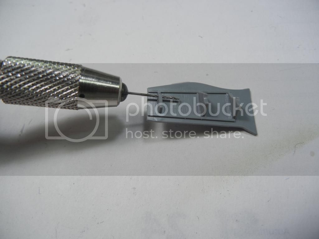
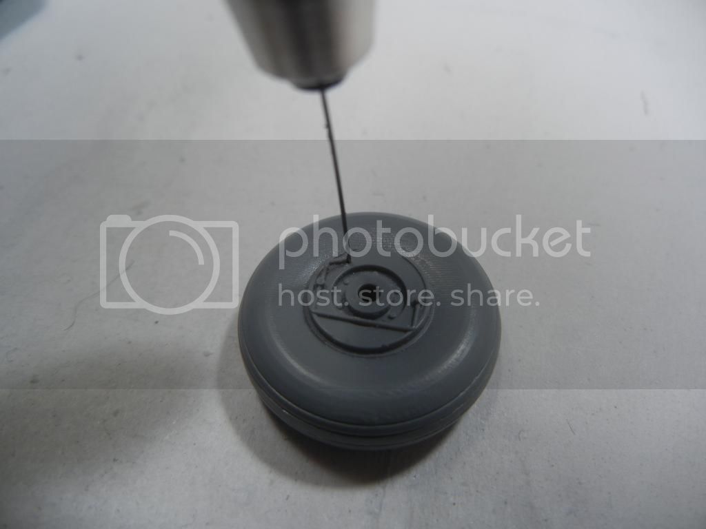
I then cut some .20 brass tube to create the brackets that hold the brake lines, and attached them to the appropriate spots on the gear leg.
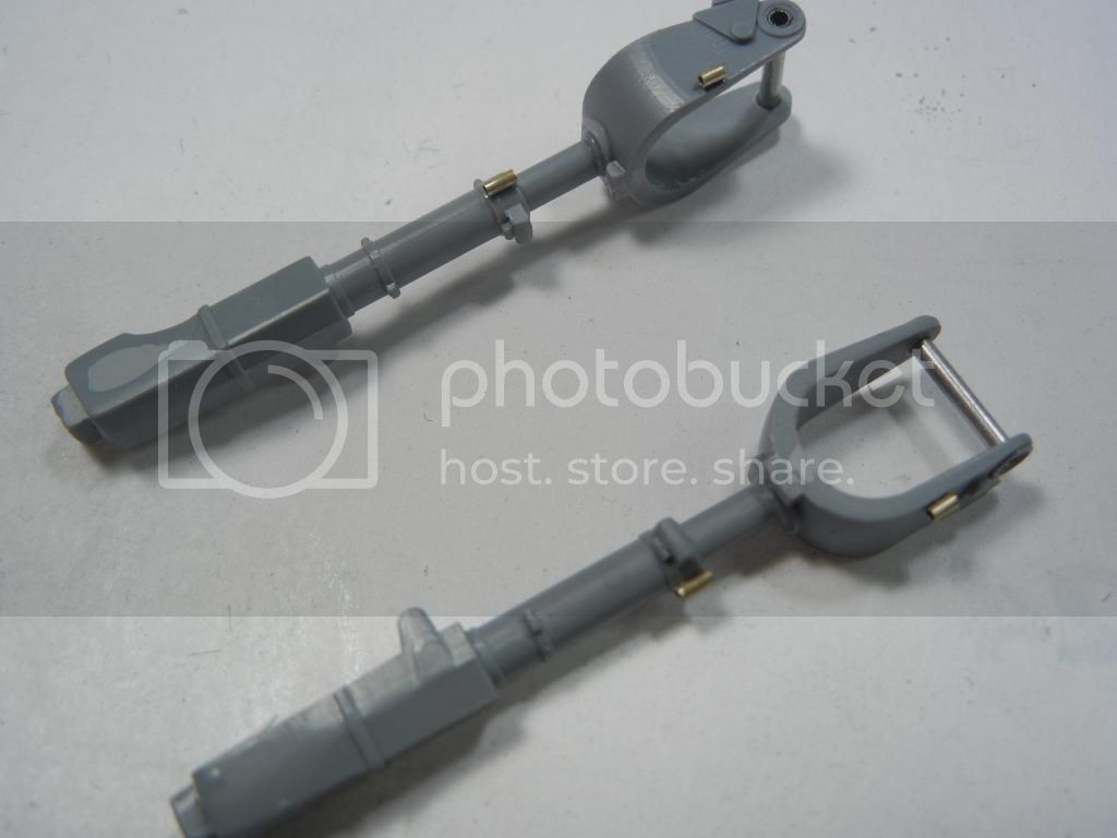
I then used some strips of Tamiya tape to create the brackets.
Next I bent some .20 steel wire to represent the inflexible part of the brake line system and test fit it in place.
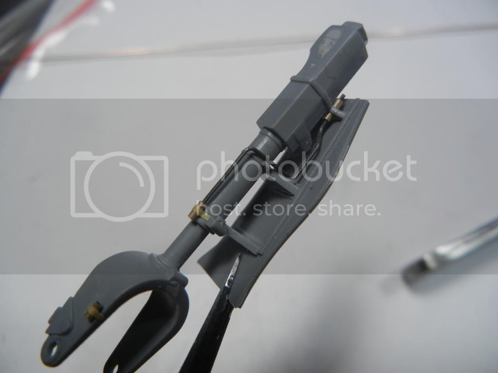
I then added some .20 solder wire to represent the flexible part of the lower brake line
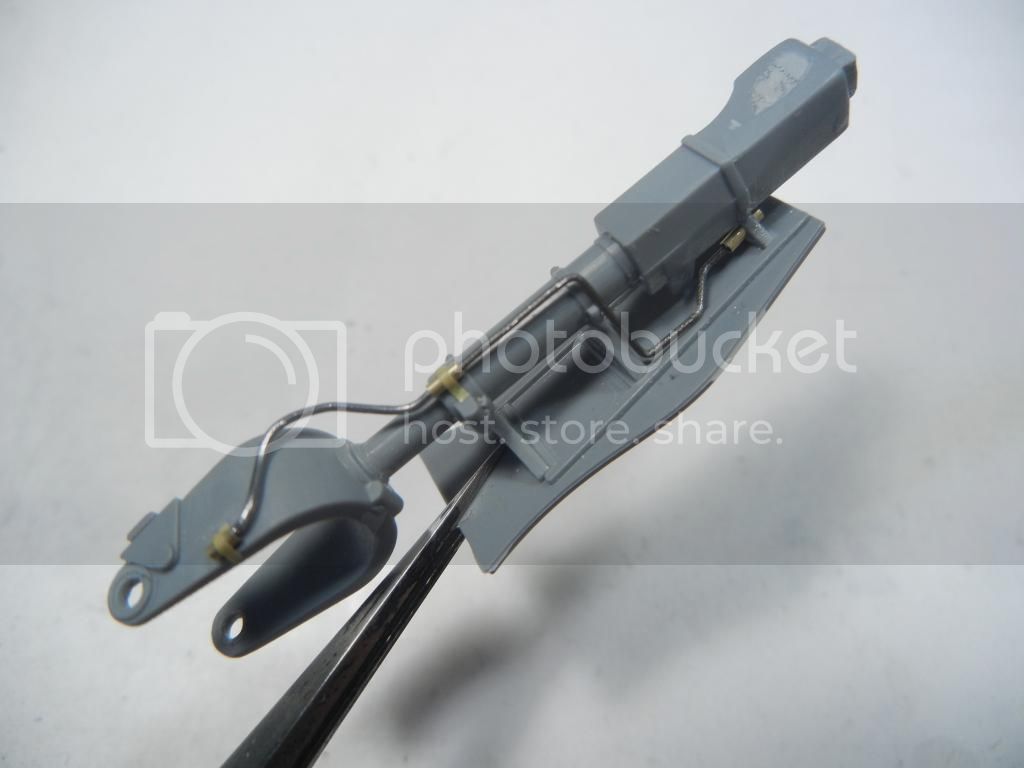
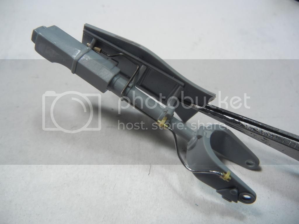
So far, I'm pleased with the progress on the brake lines. Still a little tweaking to do. At this point, I need to finalize the fit of the gear legs to the airframe, and then paint them. Once that is done I can add the brake lines and install the gear legs.
Thats all for today.
Thanks for looking! Comments/questions/critique always welcome!
Doug

Did a little more work on the gear legs. Unfortunately, the kit doesn't provide any brake lines (common to most kits). Fortunately, Radu's second IAR-80/81 book has some great drawings that show the brake line configuration. Thus armed, I decided to see if I could replicate this.
I started by drilling out a hole in the upper gear door as the brake line runs through the bracket. I also drilled a hole in the wheel hub to accept the brake line.


I then cut some .20 brass tube to create the brackets that hold the brake lines, and attached them to the appropriate spots on the gear leg.

I then used some strips of Tamiya tape to create the brackets.

Next I bent some .20 steel wire to represent the inflexible part of the brake line system and test fit it in place.

I then added some .20 solder wire to represent the flexible part of the lower brake line


So far, I'm pleased with the progress on the brake lines. Still a little tweaking to do. At this point, I need to finalize the fit of the gear legs to the airframe, and then paint them. Once that is done I can add the brake lines and install the gear legs.
Thats all for today.
Thanks for looking! Comments/questions/critique always welcome!
Doug
Posted: Friday, February 06, 2015 - 12:25 AM UTC
Hi Doug
Absolutely gorgeous work on the brake lines!
All the best
Rowan
Absolutely gorgeous work on the brake lines!

All the best
Rowan


DougN1

Joined: August 08, 2011
KitMaker: 410 posts
AeroScale: 409 posts

Posted: Saturday, April 25, 2015 - 06:04 PM UTC
While it's been some time since my last update, progress has indeed been happening, although a a glacier-like pace 
After the gear legs, I decided to finish up the engine, which meant adding the exhausts. The instructions would have you attach the small plastic pipes that mate to the cylinders to the large resin exhausts. However, since I was unsure if they would all align correctly, I decided to simply attach the plastic parts to the cylinders first.
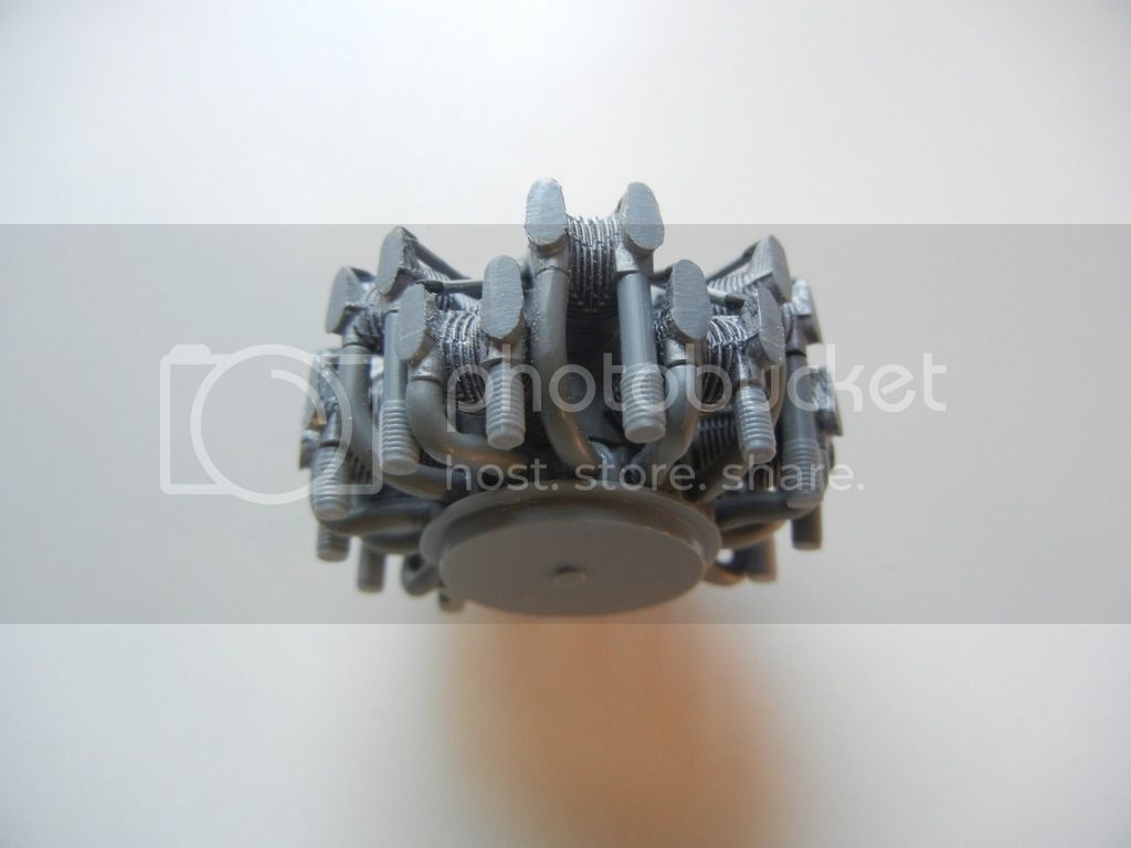
I also drilled out the ends of the 3 exhaust pipes that go on the bottom of the engine to improve their appearance.
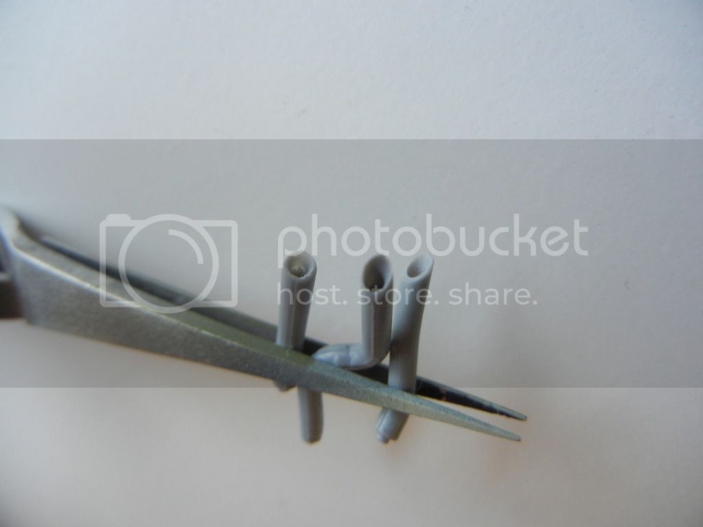
I attached the resin exhausts, and while the attachment points did not all line up perfectly, it doesn't really matter since they won't be seen once the cowling is on. Once attached, I painted the exhaust parts flat black and then drybrushed some steel over that.
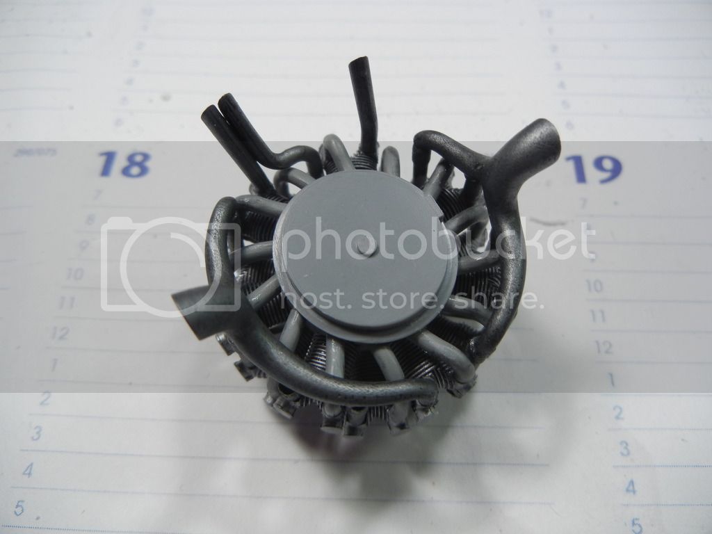
One thing to be careful of is the alignment of the bottom 3 exhausts. They need to clear the center air intake, and the side with 2 pipes needs to be adjusted to make that happen.
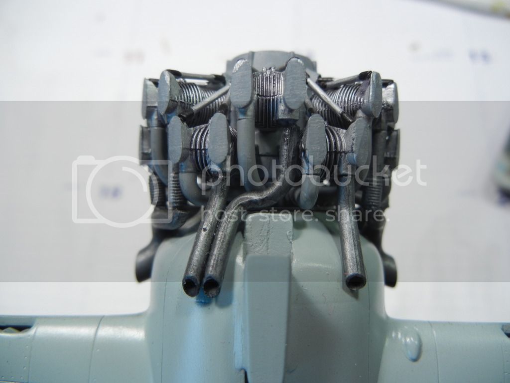
Once everything was attached and test fit, I sprayed a mixture of highly-thinned redbrown+black over the exhaust to give it a used look.
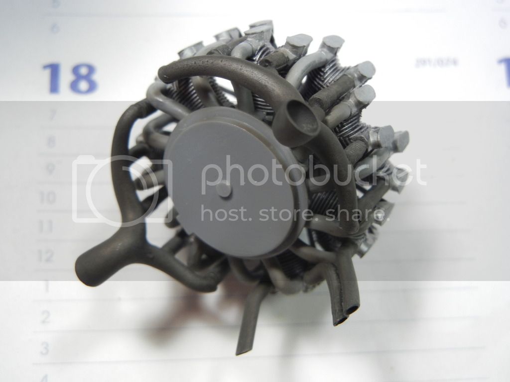
Test fit of the finished engine to the fuselage
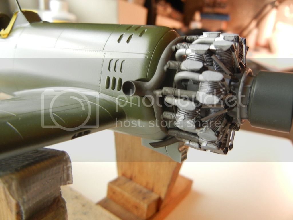
Thats all for this update. Thanks for looking, comments/critique/questions always welcome!
Doug

After the gear legs, I decided to finish up the engine, which meant adding the exhausts. The instructions would have you attach the small plastic pipes that mate to the cylinders to the large resin exhausts. However, since I was unsure if they would all align correctly, I decided to simply attach the plastic parts to the cylinders first.

I also drilled out the ends of the 3 exhaust pipes that go on the bottom of the engine to improve their appearance.

I attached the resin exhausts, and while the attachment points did not all line up perfectly, it doesn't really matter since they won't be seen once the cowling is on. Once attached, I painted the exhaust parts flat black and then drybrushed some steel over that.

One thing to be careful of is the alignment of the bottom 3 exhausts. They need to clear the center air intake, and the side with 2 pipes needs to be adjusted to make that happen.

Once everything was attached and test fit, I sprayed a mixture of highly-thinned redbrown+black over the exhaust to give it a used look.

Test fit of the finished engine to the fuselage

Thats all for this update. Thanks for looking, comments/critique/questions always welcome!
Doug
Joel_W

Joined: December 04, 2010
KitMaker: 11,666 posts
AeroScale: 7,410 posts

Posted: Saturday, April 25, 2015 - 07:10 PM UTC
Doug,
I just caught up as I missed your last update A(my fault). I'm more then impressed with how you scratched out the brake lines. Working in 1/32 scale does have it's advantages over the smaller scales I've been working in.
The engine and exhaust system really turned out quite well, and with the cowling on, the misalignment won't be a visual issue.
Now on to the paint shop.
Joel

DougN1

Joined: August 08, 2011
KitMaker: 410 posts
AeroScale: 409 posts

Posted: Friday, June 19, 2015 - 01:49 AM UTC
Time to rescue this build from page 5 
Finally got to spend some quality time with the IAR-81. With the major paintwork completed, what is left is mostly getting all the various bits on that we always leave for last to avoid damaging them like these:
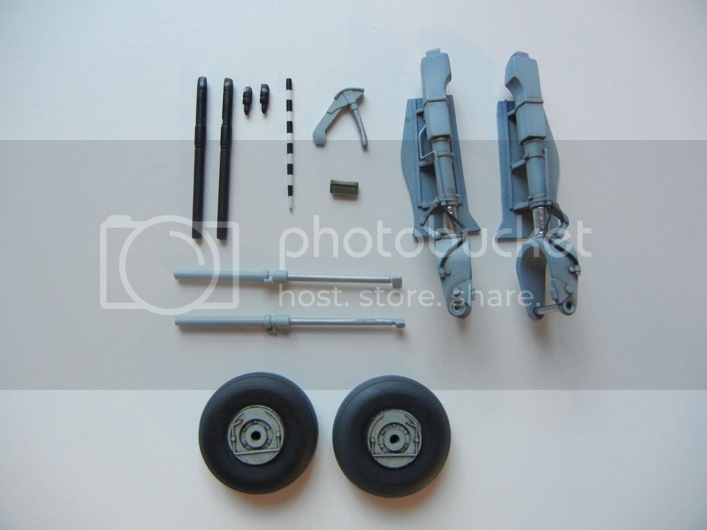
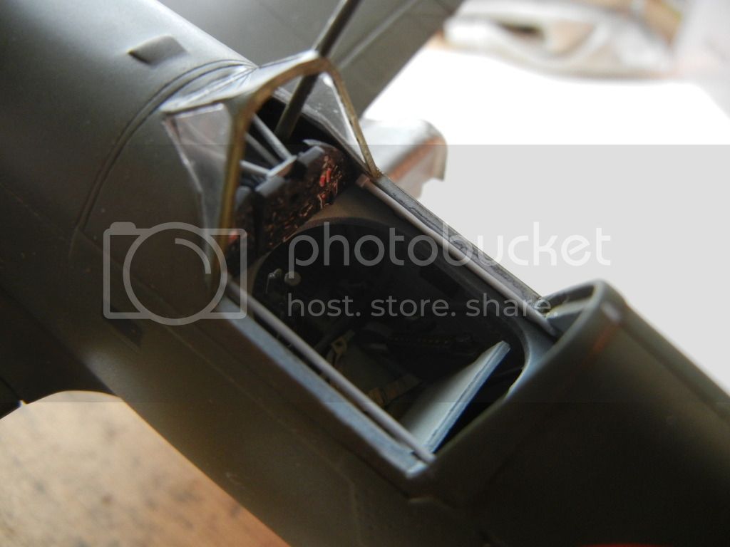
I unmasked the cockpit/canopy and attached the canopy frame rails. The instructions seem to tell you to attach them to the cockpit decking, but you really need to attach them to the sidewalls so they sit with the top just barely above the sill like so:
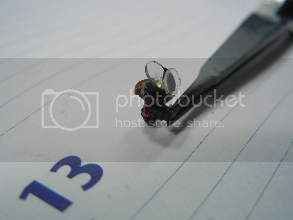
I also built up the beautiful kit gunsight, adding an MV lens for the reflector:
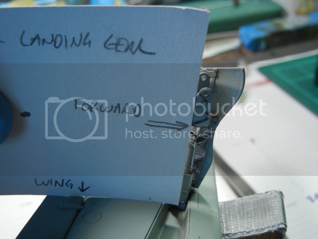
Then the time came to finally get the gear legs on. As mentioned previously, I had to enlarge the hole and do a little grinding to get an optimal fit of the gear leg to the wing. To ensure the proper angle, I made a template using the excellent drawings in Radu's book like so:
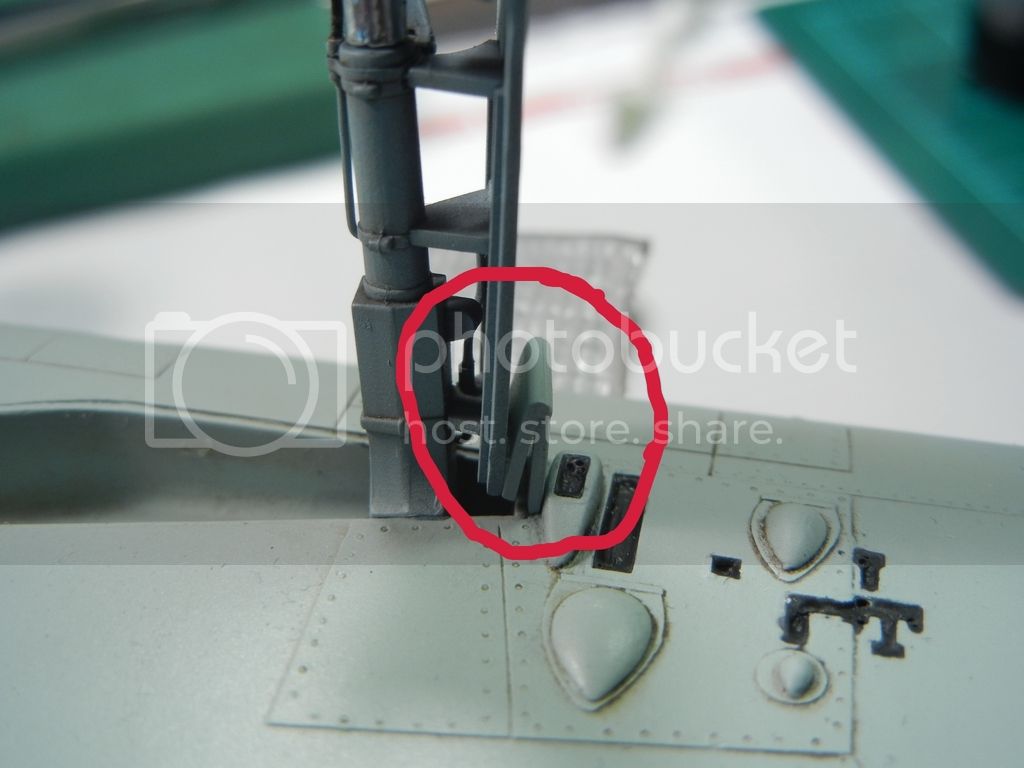
Once that was done, I needed to add the two outer door bits, which are a tight fit, but I got them nicely in place nonetheless:
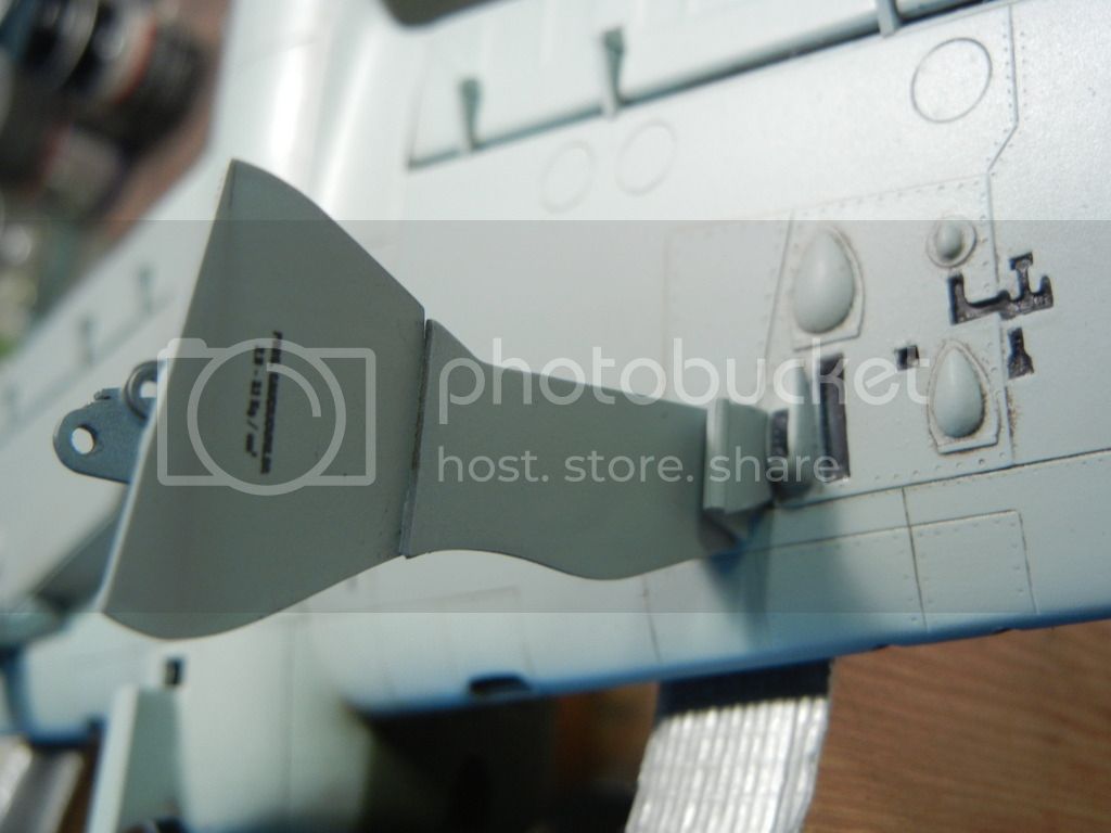
I attached the bomb brackets as well. These are optional, and were often removed in the field. If you don't attach them be sure to fill in the depressed areas as a new sheet metal panel was used when they were removed.
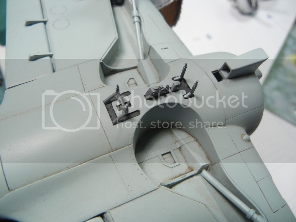
I also painted the leather boot covers and attached the tailskid:
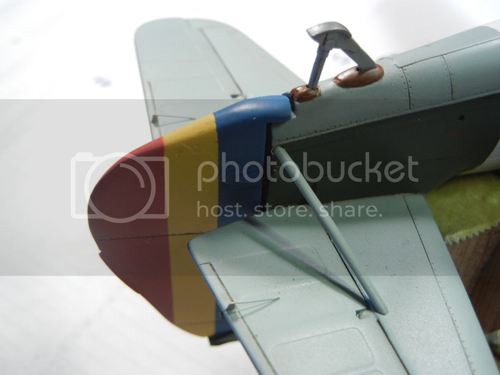
Also note the fuselage attachment point for the tailplane support struts, as this is not indicated well in the instructions.
That brings us up-to-date, and I hope to be able to get this build finished in the next week or so time permitting!
Thanks for looking, comments/critique/questions always welcomed.
Doug

Finally got to spend some quality time with the IAR-81. With the major paintwork completed, what is left is mostly getting all the various bits on that we always leave for last to avoid damaging them like these:

I unmasked the cockpit/canopy and attached the canopy frame rails. The instructions seem to tell you to attach them to the cockpit decking, but you really need to attach them to the sidewalls so they sit with the top just barely above the sill like so:

I also built up the beautiful kit gunsight, adding an MV lens for the reflector:

Then the time came to finally get the gear legs on. As mentioned previously, I had to enlarge the hole and do a little grinding to get an optimal fit of the gear leg to the wing. To ensure the proper angle, I made a template using the excellent drawings in Radu's book like so:

Once that was done, I needed to add the two outer door bits, which are a tight fit, but I got them nicely in place nonetheless:


I attached the bomb brackets as well. These are optional, and were often removed in the field. If you don't attach them be sure to fill in the depressed areas as a new sheet metal panel was used when they were removed.

I also painted the leather boot covers and attached the tailskid:

Also note the fuselage attachment point for the tailplane support struts, as this is not indicated well in the instructions.
That brings us up-to-date, and I hope to be able to get this build finished in the next week or so time permitting!
Thanks for looking, comments/critique/questions always welcomed.
Doug
Joel_W

Joined: December 04, 2010
KitMaker: 11,666 posts
AeroScale: 7,410 posts

Posted: Friday, June 19, 2015 - 03:12 AM UTC
Doug,
It's nice to see another update as you're certainly in the home stretch with the addition of all those little last minute pieces.
Joel
It's nice to see another update as you're certainly in the home stretch with the addition of all those little last minute pieces.
Joel
Posted: Saturday, June 20, 2015 - 09:55 PM UTC
Hi Doug
It's great to see you back with this one. The devil, as they always say, is in the details - and you've done some fantastic detail work there!
All the best
Rowan
It's great to see you back with this one. The devil, as they always say, is in the details - and you've done some fantastic detail work there!

All the best
Rowan


DougN1

Joined: August 08, 2011
KitMaker: 410 posts
AeroScale: 409 posts

Posted: Friday, July 10, 2015 - 11:25 PM UTC
Thanks guys!
Just had a few more things to do to finish this one up.
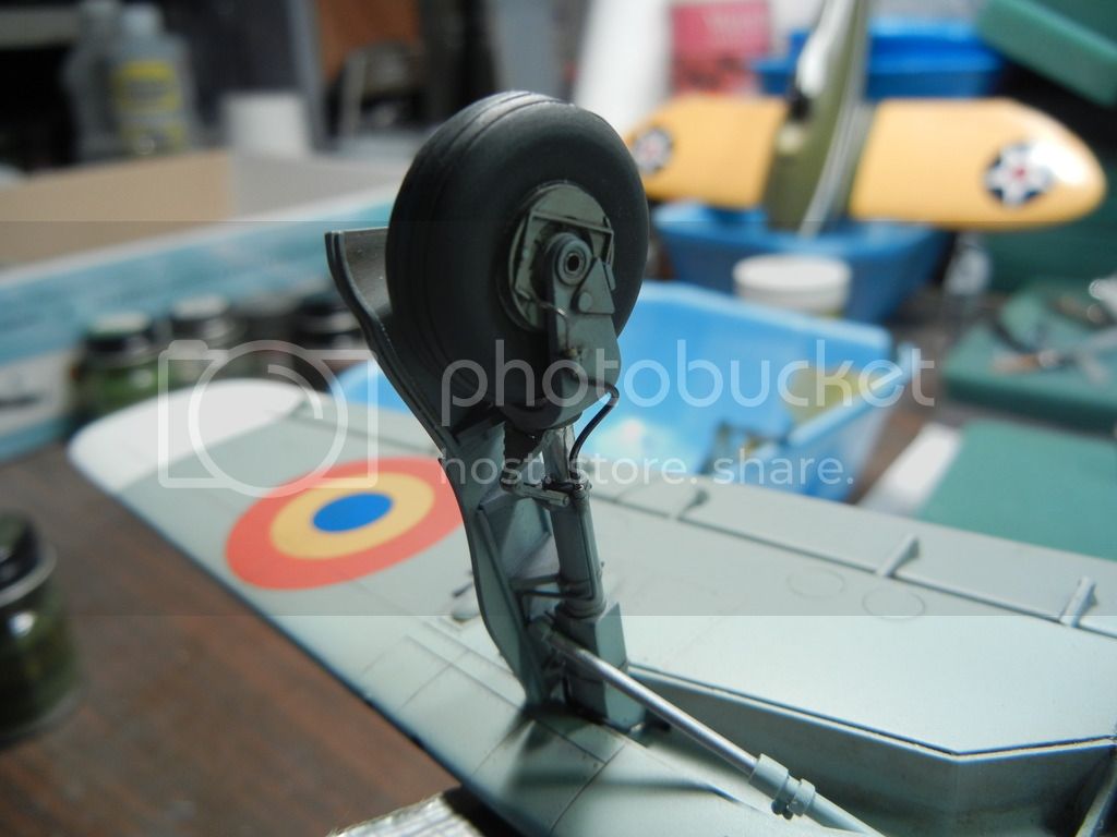
Attached the wheels and the final bit of brake line:
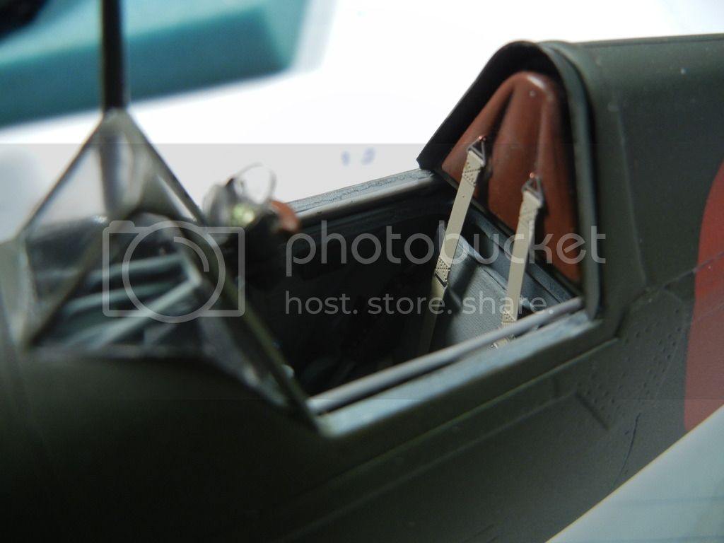
I attached the seat belts to the armor plate/cushion part using some fine wire to make loops and put them through the hole I drilled out previously. I then attached that to the model:
The kit doesn't provide the tail light, so I added an MV lens to replicate that bit. Need to clean up the white glue when it dries and it should look great:
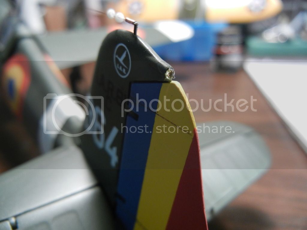
You can also see I've added the aerial wires, springs and cones, etc. in the pic above.
Attached the pitot, guns, canopy and other assorted small bits and that wraps this one up (finally):
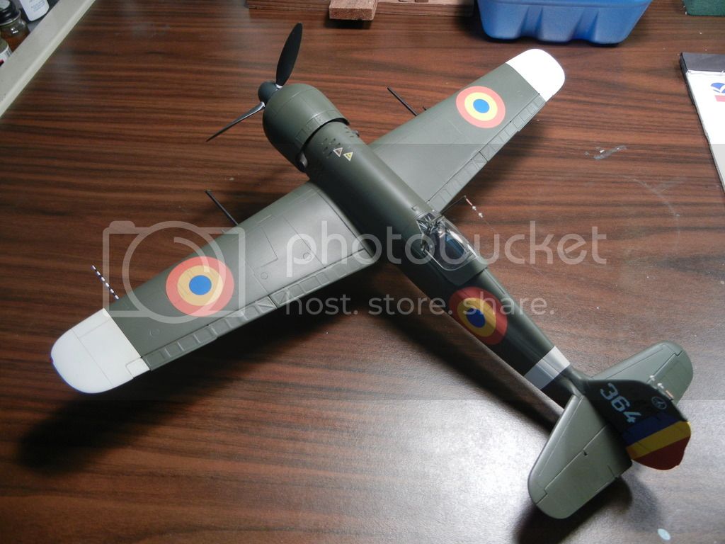
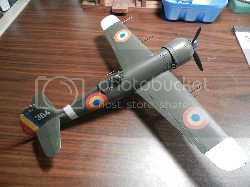
I'll take some glamour shots soon
Thanks for looking and to those who have followed along and commented! Comments/questions/critique always welcome.
Doug
Just had a few more things to do to finish this one up.
Attached the wheels and the final bit of brake line:

I attached the seat belts to the armor plate/cushion part using some fine wire to make loops and put them through the hole I drilled out previously. I then attached that to the model:

The kit doesn't provide the tail light, so I added an MV lens to replicate that bit. Need to clean up the white glue when it dries and it should look great:

You can also see I've added the aerial wires, springs and cones, etc. in the pic above.
Attached the pitot, guns, canopy and other assorted small bits and that wraps this one up (finally):


I'll take some glamour shots soon

Thanks for looking and to those who have followed along and commented! Comments/questions/critique always welcome.
Doug
Posted: Saturday, July 11, 2015 - 12:43 AM UTC
Hi Doug
Really nice! As ever, the small details in your work are exquisite!
All the best
Rowan
Really nice! As ever, the small details in your work are exquisite!

All the best
Rowan

Joel_W

Joined: December 04, 2010
KitMaker: 11,666 posts
AeroScale: 7,410 posts

Posted: Saturday, July 11, 2015 - 08:57 PM UTC
Doug,
those small details really make a special build just that much better. That one overall picture is just a tease to what a full set will look like.
Joel
those small details really make a special build just that much better. That one overall picture is just a tease to what a full set will look like.
Joel

DougN1

Joined: August 08, 2011
KitMaker: 410 posts
AeroScale: 409 posts

Posted: Wednesday, August 05, 2015 - 10:00 PM UTC
Thanks guys, it was a good build and I look forward to doing another in the future!
 |


