_GOTOBOTTOM
Early Aviation
Discuss World War I and the early years of aviation thru 1934.
Sopwith Camel 1/16 Hasegawa out-of-the-box
MichaelSatin
Staff MemberCampaigns Administrator
AEROSCALE
_VISITCOMMUNITY
Colorado, United States
Joined: January 19, 2008
KitMaker: 3,909 posts
AeroScale: 2,904 posts
Posted: Monday, September 01, 2014 - 10:23 AM UTC
OK folks, strap yourselves in. I promised myself I was going to finish this beast and over the last two days I have, but it wasn't always smooth sailing. Here's the first installment which deals mainly with the wing installation and rigging:

First things first; as I said above, get those lower wings glued on so they can set up solid. Note the gap between the wings and the fuselage. This is supposed to be there, so don't panic.
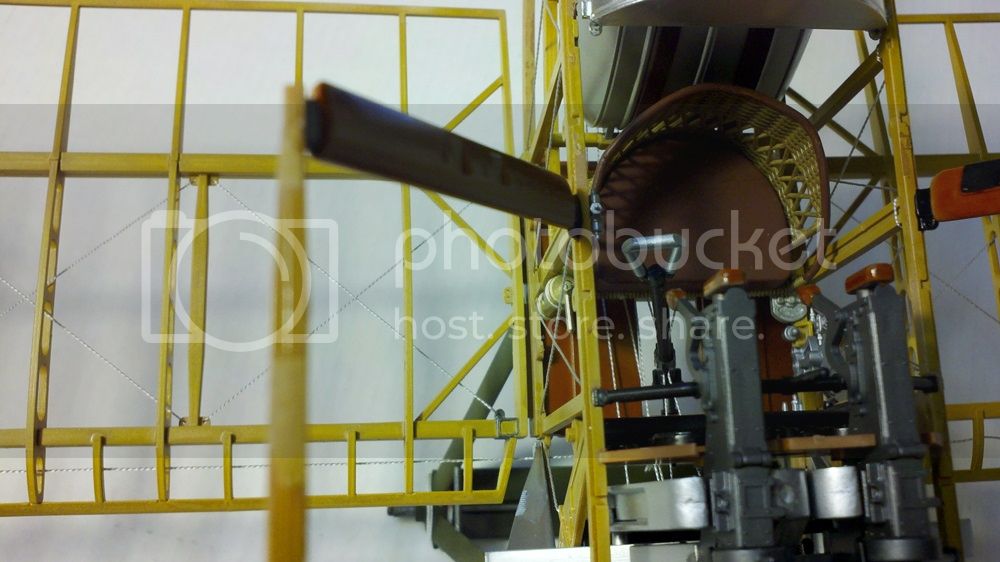
 photo lowerwinggap_zpsc74a0f4b.jpg

They will be covered up later by side panels.

Next lead those aileron control cables that have been flopping around this whole time through the leading edge of the wings to the pulleys. Be careful to go through the holes in the ribs so the wires are fully within the leading edge:
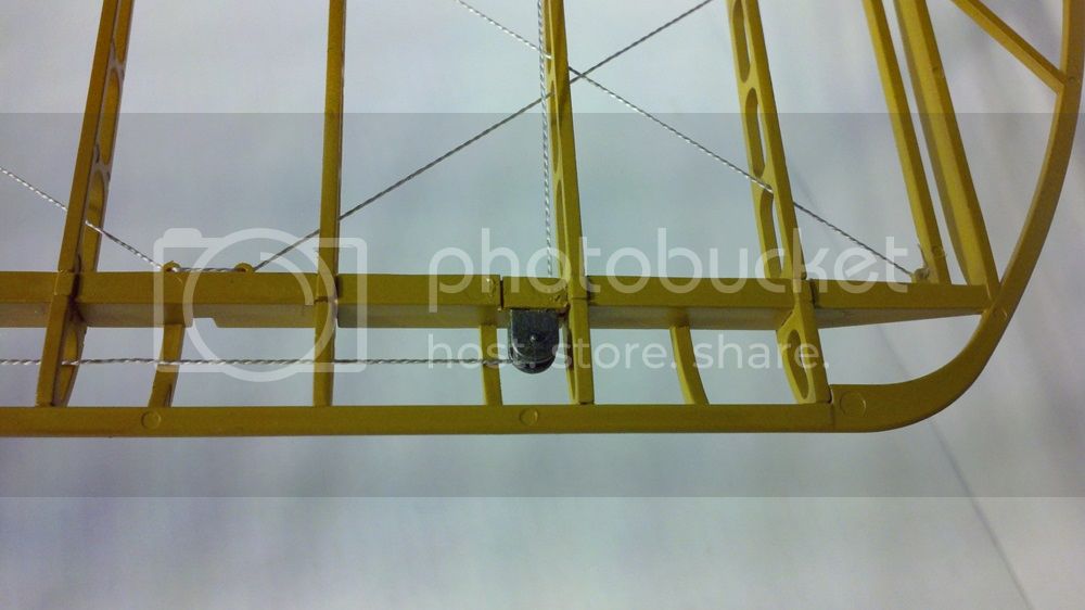
 photo aileroncontrolaroundpulley_zps6bfc1d67.jpg

If you were careful putting the pulley parts in, there will be a gap you can thread the cables though to go back to the ailerons. You were careful, right?

Once threaded aft, run the cables through the holes in the control horns and to the guide aft of it:
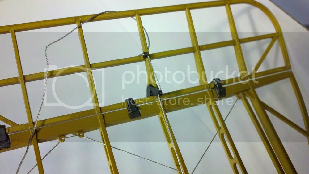
 photo aileroncontrolthroughhorn_zpscde646a4.jpg

Don't apply glue to the control horn or guide yet, you'll need things to be able to move when you attach the top wing.

Once the aileron controls are fed through the lower ailerons, it's time to install the interplane struts into the lower wing. Here's how they fit:
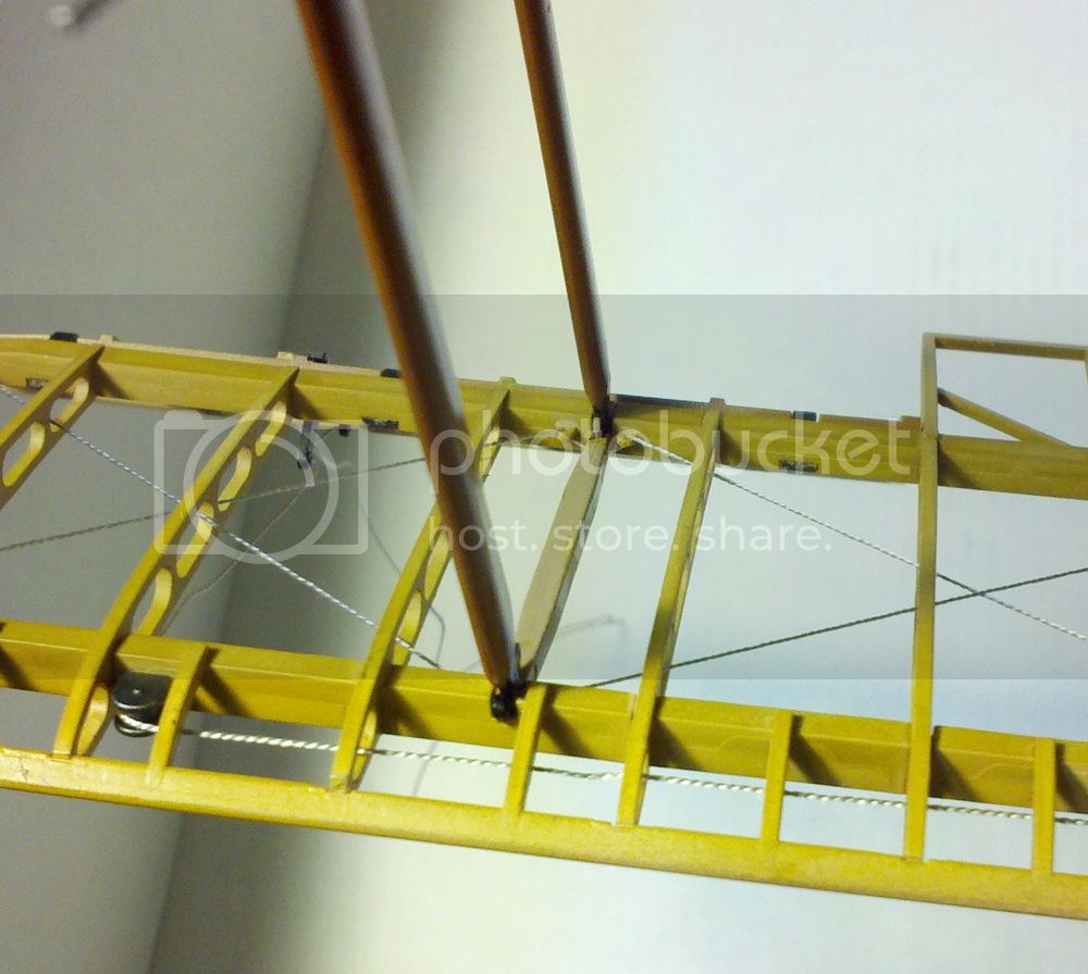
 photo interplanestrutmountinglowerwing_zps64b85fe5.jpg

You'll want to get these installed with time to install the upper wing too. As is so often true with biplanes, it's the cabane struts that really line everything up; especially on this kit where Hasegawa molded them integrally with the fuselage sides. So you'll want the interplane struts to still be a little flexible when you get the top wing on. They line up fine fore and aft, but not so much up and down.

Here's the cabane struts installed in the top wing from above:
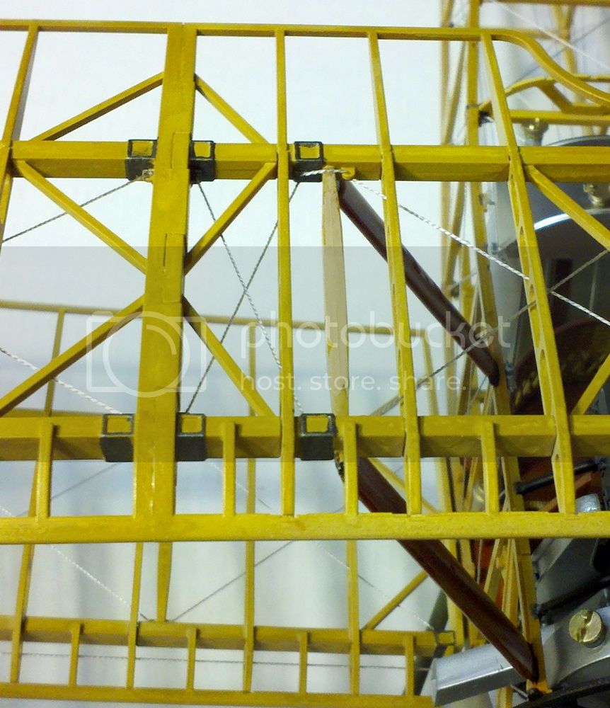
 photo cabinestrutmountingupperwing_zps3d41943d.jpg

And here is what the interplane struts look like from above:
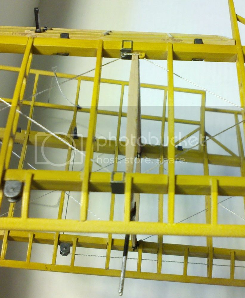
 photo interplanestrutmountingupperwing_zps1f0bd12f.jpg

And yes, I forgot to paint the top of the struts which become a rib. What you see is the base coat of Wood Deck Tan before the clear yellow overcoat.

The upper wing has an aileron return cable that feeds though the leading edge and to the control horns on the upper ailerons much like the lower. Here it is in the leading edge:
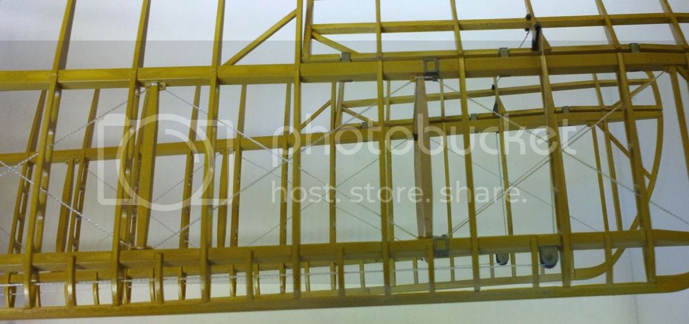
 photo aileronreturnupper_zps5c47018f.jpg

And here's a (not so great, sorry) picture of it attached to the control horn:
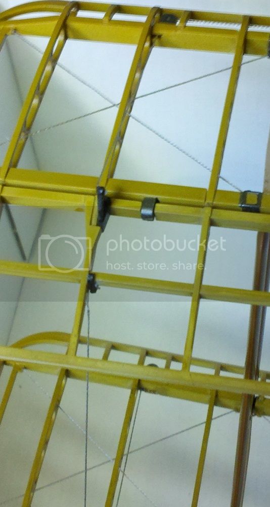
 photo aileroncontrolattachedupper_zps95dd7b99.jpg

Note that unlike the lower wing control cable, the control horn is not attached to the guide at the back of the aileron. The lower cables do the controlling, the upper cable is only to keep the system honest. Make sure that when you attach the two ends of the upper return cables to their control horns the ailerons are in neutral position (or one up and one down) so it does its job correctly. Then hook up the control cables from the bottom ailerons to the anchor at the back end of the top ailerons. Make sure everything (including the control stick) is in neutral position when you commit to glue. Two or three extra hands help.

By the way, I didn't actually glue the thread at the lower control horns until everything was set up. This allowed me to make sure the control stick and the ailerons matched up. It'll make more sense when you actually do it. I hope.

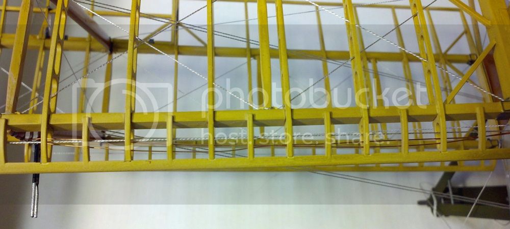
Right! Now it's time to start the outer wing bracing. First step is easy enough, one wire each side between the cabane struts:
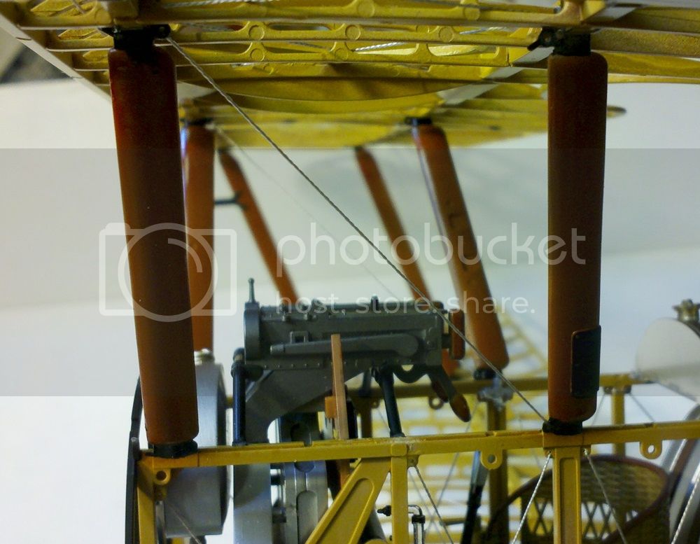
 photo firstwingbracingline_zps9005307a.jpg

And that's where the easy stops. Hasegawa would have you do each side with only two more pieces of thread each. And lo and behold, it works! But it's complicated and requires you to be very careful (again) not to tangle things up. This is especially important with the doubled wires (ask me how I know). Here's the port side with the first thread done:
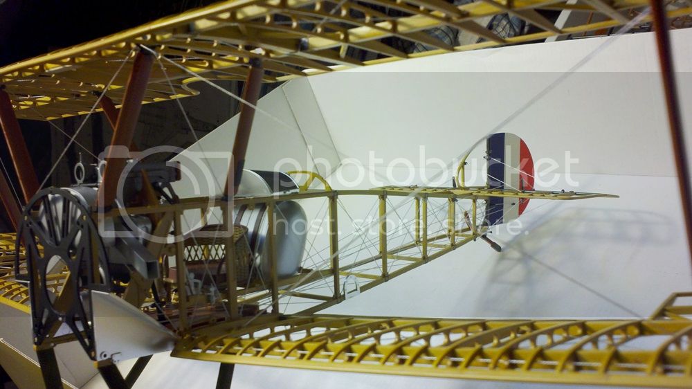
 photo secondwingbracingline_zps53113625.jpg

Here's the anchor point where it started:
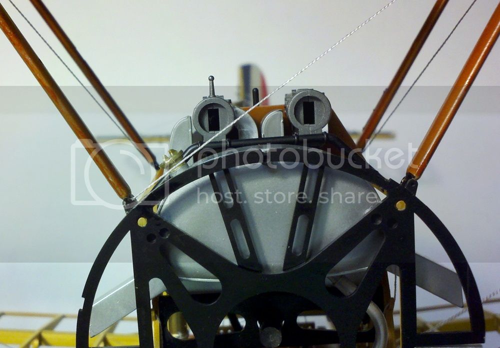
 photo secondwingbracinglinestart_zpsda959742.jpg

Again, I did not cut off a length of line but just fed it through this hole and then led it through the others as shown in the instructions. This actually worked, by the way. Once I was at the end (I believe it was the top of the aft interplane strut, but I could be wrong) I glued it there and let it set up. Then I made sure everything was taut (but not enough to pull anything out of line) and glued it back at the starting point, then cut the line there. Next on to thread number two, starting this time at the bottom of the forward cabane and going from there:
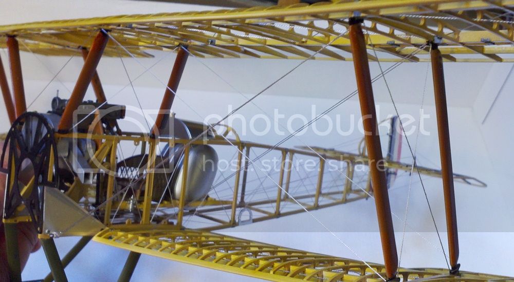
 photo portwingbracinginstalled_zps824da654.jpg

This also worked, and when it was done, the entire port side was rigged! Frankly I still can't believe this actually did the job. So, to be sure, I did the starboard side. Pretty crazy, basically four steps and it's all done:
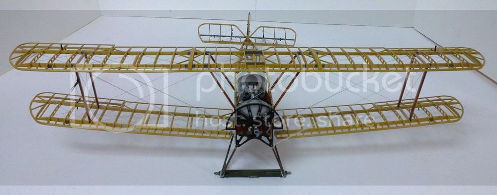
 photo wingbracinglinesdone_zps7d18144e.jpg

OK, I promised you I would get done with this thing and I will, but not until the next post. See you then!

Michael
MichaelSatin
Staff MemberCampaigns Administrator
AEROSCALE
_VISITCOMMUNITY
Colorado, United States
Joined: January 19, 2008
KitMaker: 3,909 posts
AeroScale: 2,904 posts
Posted: Monday, September 01, 2014 - 11:00 AM UTC
And here we go...

I said I'd be done and here's the last push.

Our friends at Hasegawa still have some tricks up their sleeves, so pay attention.

First thing here is to attach the side panels. Hasegawa have them numbered showing which one to install first. Follow those numbers or you'll be sorry. I think these should be removable, but how to do that and still get everything attached is beyond me at this point, so I glued 'em in. I have pictures to show the inside.

 photo sidepanelson_zps3ffbf6b6.jpg

By the way, something I didn't note before. Much of this would be impossible on a smaller scale aircraft due to the lack of maneuvering room to get stuff inside the rigging. On one this size, however, you can get away with it. And while the holes are small, the thread is resilient so if (when) you knock the threads you can get away with it if you don't get too ham fisted.

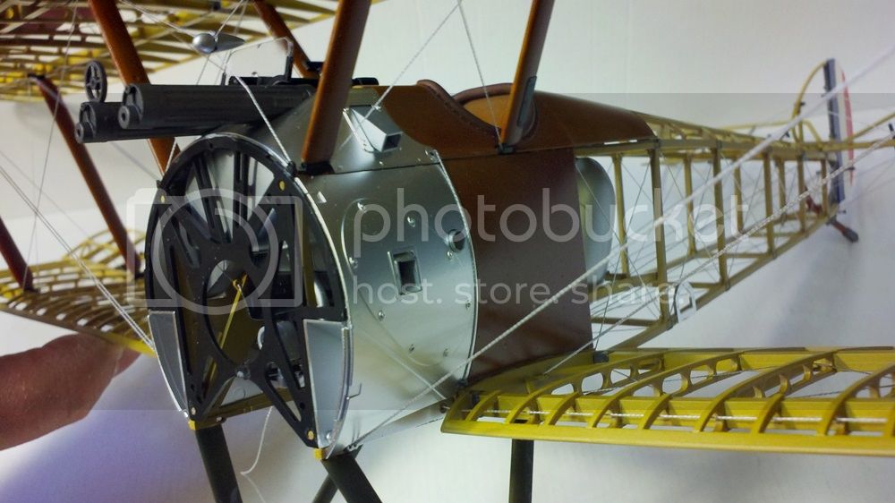
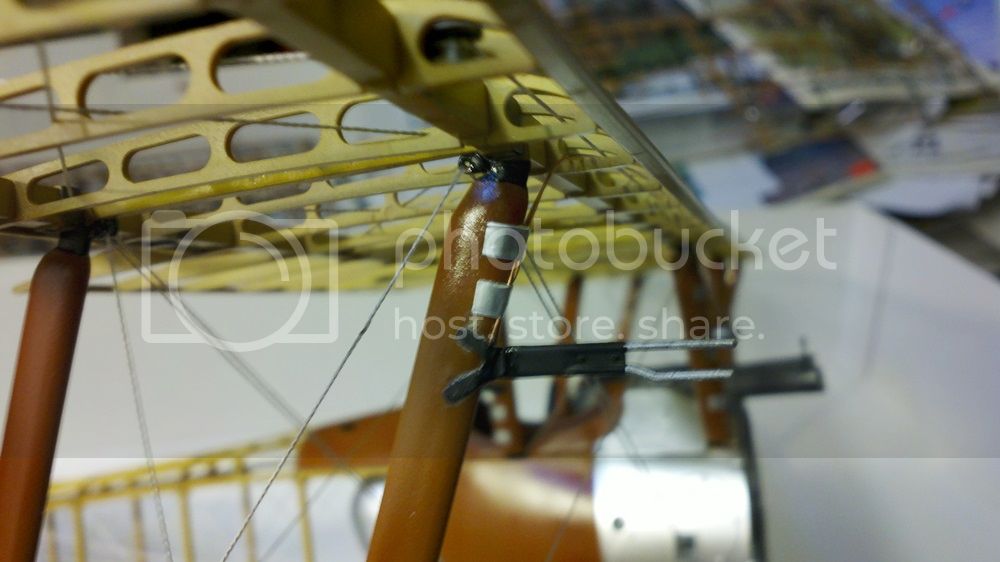
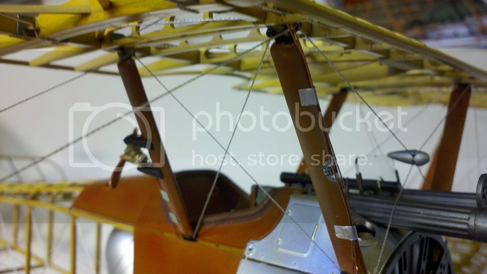
OK, side panels on. Now it's on to a couple of interesting features; the pitot head and the Rotherham wind-driven pump. Hasegawa not only include these, they wire them. Having whacked the pitot head (which was installed on the starboard leading edge interplane strut earlier) a few times, I would recommend leaving it off altogether until this point. But now's the time. Hasegawa include copper wire and adhesive foil for straps and now you cut and install them. They tell you how much to cut but it's a little unclear that the pitot needs two (not "tow") pieces of wire. Glue to the top of the pitot head, lead up to the wing

 photo pitotheadwiring_zps12e48622.jpg

and thread through the leading edge ribs like you did with the return cable earlier:

 photo pitotheadwiringinleadingedge_zpsd45efe22.jpg

Then down the cabane strut to the top of the gun cover and inside the fuselage. After that it disappears.

 photo Rotherhampumpandpitotwiring_zps177421ef.jpg

The pump works much the same way but much shorter, straight down the strut to the cockpit. I left the small prop off the pump until the wiring was done to keep it out of the way.

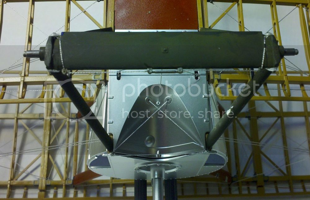
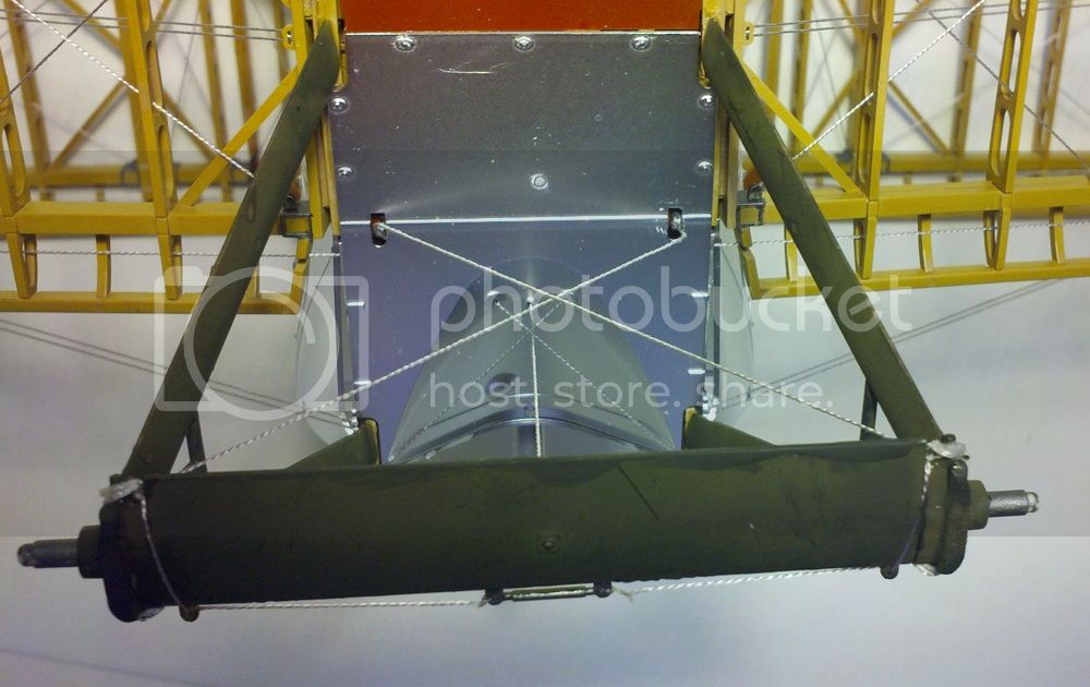
Right, now it's time to flip the beast over and start with the bottom of the fuselage. Install the bottom panels (again in the order Hasegawa call out) being sure to attach the rigging threads as shown.

 photo undercarriageriggingfront_zps40599d78.jpg

There are a couple of small rigging anchors that attach through slots in the bottom engine panel. Tie and glue on the rigging threads before you glue the anchors in, it'll make the job much easier. Oh, those anchors. You will use several of them in these last steps. Do yourself a favor and ream out the holes a little on them first, they're too small.

Now you're rigging the undercarriage bracing, and here's where I found out that I was too clever earlier. Remember where I said I wrapped the "bungee" cords around the axles before Hasegawa said so because it was easier? Well, bad idea. In the picture below, see where the bracing wire feeds through the axle "wing" from behind?

 photo undercarriageriggingback_zps38781469.jpg

Yeah, I fouled those holes with the "bungee". THAT was fun to try to fix! Don't make the same mistake, wait on those bungees until the instructions tell you to do them.

Wow, look at how complicated that all looks! It was easier to do than it looks (aside from my mistake.) It doesn't look too square from the pic, but it turned out just fine.

Now it's the race to the finish. There a bracing line that runs around the outside of the cowling through some brackets, not hard but refer to the 1:1 size rigging diagram as the instructions aren't too clear. The engine fits onto the prop shaft with a slot and cam set up inside, be sure to line them up. Yes, the engine turns with the prop. Both the prop and the wheels have small grommets inside so they can be press fit on.

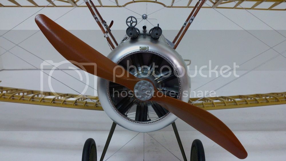
And this was the place I blew it. Hasegawa gives you special press on decals for the tires (no doubt copied from their car kits). I tried to put them on as instructed and completely hosed them up. So no lettering on the tires. Sigh. You'll also notice in the pics of the finished model that I could not figure out the bullet fairing on the crossed wires over the guns. If anyone has a better plan on how to install that, feel free to post.

Decals on the struts (yes, Sopwith folded them over the leading edges) and she's DONE! See below.

Michael
MichaelSatin
Staff MemberCampaigns Administrator
AEROSCALE
_VISITCOMMUNITY
Colorado, United States
Joined: January 19, 2008
KitMaker: 3,909 posts
AeroScale: 2,904 posts
Posted: Monday, September 01, 2014 - 11:15 AM UTC
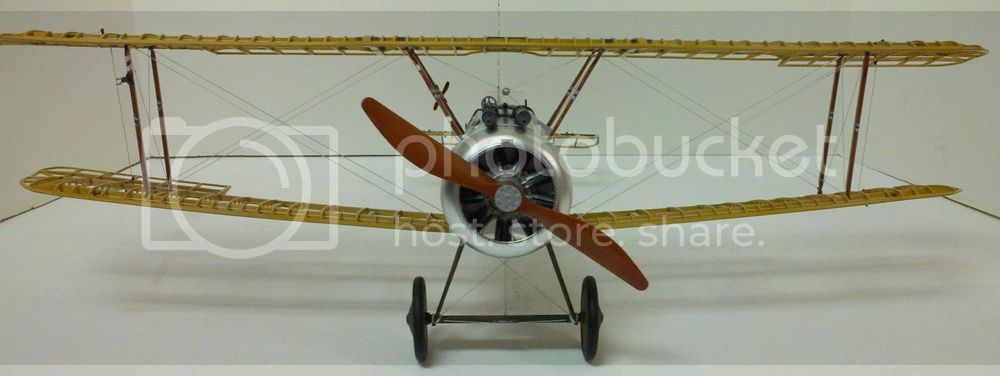
OK, here's the finished product:

 photo completeheadon_zps2157a1b8.jpg

 photo completebusinessend_zps85c3c692.jpg

 photo completeaft_zpsc16a8bcb.jpg

 photo completetopaft_zps645c4368.jpg

 photo completeundercarriageaft_zpsb4c577d0.jpg

Would I do some things differently if I did it again? Yes, probably. But all in all if you follow the instructions you won't go far wrong. Hasegawa give you plenty of thread, wire, straps, etc. to do everything with lots left over, so don't worry about that. If you mis-measure a couple of lines, there's enough to try again. Also, where they give you measurements they include enough for tying off and "slop", so you're good there too. Coat the ends of those lines in cyano glue as directed, it takes a little time but is a heck of a lot easier to thread through the small holes.

Is there room for improvement? The experts could really go to town on this one. More bracing wire, RAF wires for the interwing bracing, turnbuckles, wiring the engine and instrument panel, seat belts, etc. etc. But is it a great model out of the box?

On the whole, I'd have to say yes indeed it is! This isn't a model for the beginner. But I'm no big contest winner, just a modeler who's been around the block a few times, and I was able to handle it pretty easily if I went slowly. If you want a truly impressive Sopwith Camel on your shelf, you can't go wrong here.

Thanks to Hasegawa and Hobbico for the sample and to Jim Starkweather for trusting me with it. Any suggestions for better writing or pics or whatever will be cheerfully (well, mostly) accepted.

Ta ta and Talley Ho all!

Michael
tinbanger
_VISITCOMMUNITY
Ontario, Canada
Joined: February 04, 2008
KitMaker: 2,507 posts
AeroScale: 1,814 posts
Posted: Monday, September 01, 2014 - 01:04 PM UTC
Well done Michael!
MichaelSatin
Staff MemberCampaigns Administrator
AEROSCALE
_VISITCOMMUNITY
Colorado, United States
Joined: January 19, 2008
KitMaker: 3,909 posts
AeroScale: 2,904 posts
Posted: Wednesday, September 03, 2014 - 01:07 PM UTC
Thanks Richard! Bit of a haul but well worth it in the end.

Michael
Merlin
Staff MemberSenior Editor
AEROSCALE
#017
_VISITCOMMUNITY
United Kingdom
Joined: June 11, 2003
KitMaker: 17,582 posts
AeroScale: 12,795 posts
Posted: Thursday, September 04, 2014 - 08:42 AM UTC
Great work Michael

It's a wonderful kit that I've shied away from.

All the best

Rowan
Removed by original poster on 09/27/14 - 01:03:36 (GMT).
JackFlash
_VISITCOMMUNITY
Colorado, United States
Joined: January 25, 2004
KitMaker: 11,669 posts
AeroScale: 11,011 posts
Posted: Friday, September 26, 2014 - 01:15 PM UTC
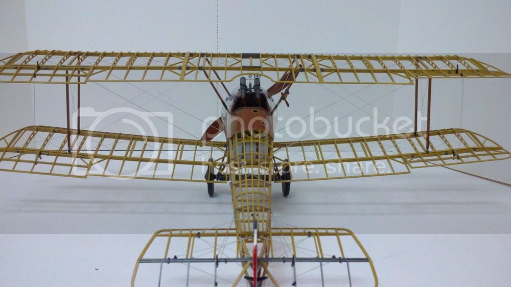
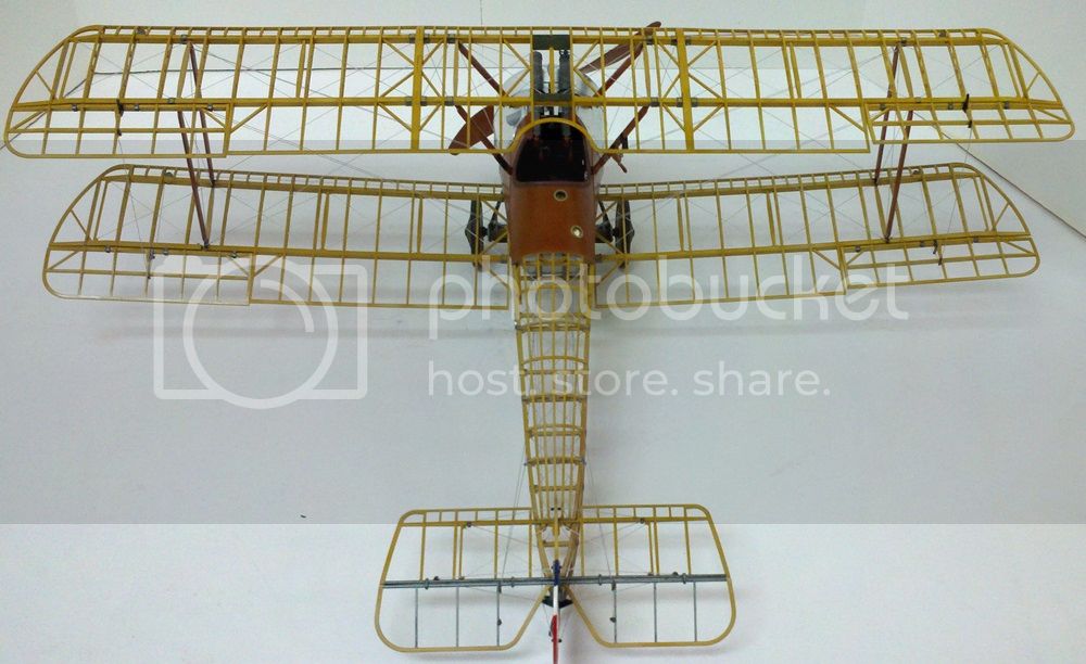
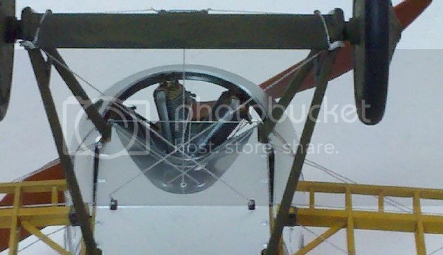
Nice work Michael. At first glance the exhaust vents looked capped. But a closer second look shows them open. Angles & lighting as it were. For anyone interested here is the same are under repair. The Clerget has the prop spindle removed and a coned shaped crank cap is exposed.

 _GOTOTOP