

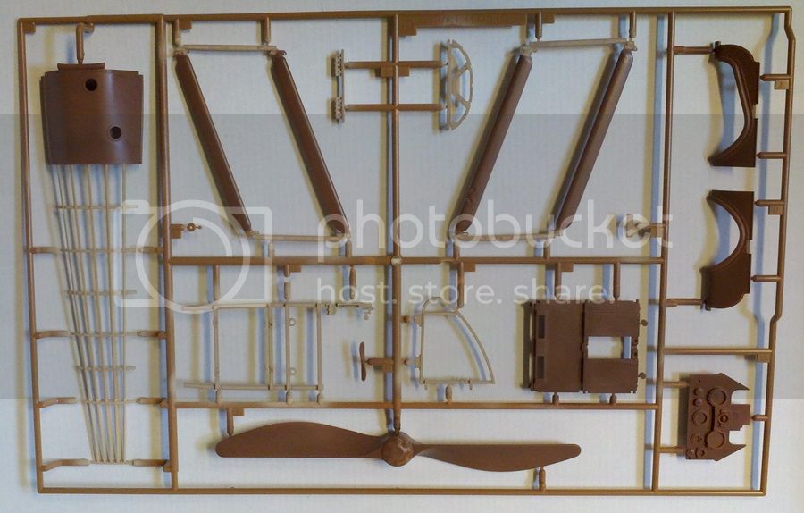
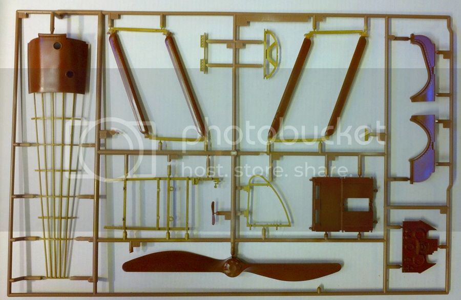
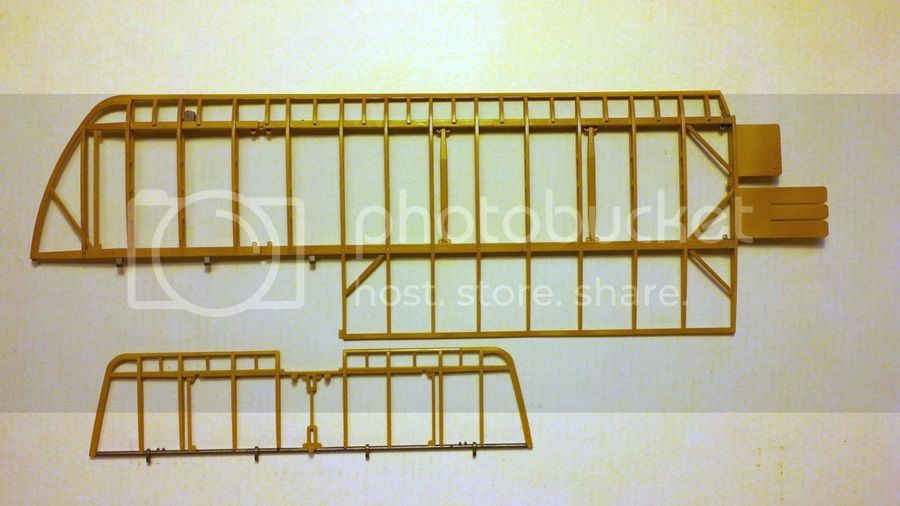
Some time ago our great and noble editor Jim Starkweather did a video review of the new Hasegawa 1/16 Sopwith Camel. You can find it here. It's an excellent out of the box look at the kit and in addition to the video there are lots of sprue shots. I was then chosen to do a build of the kit, much to my joy.
Unfortunately, upon receiving the kit and opening it up, my modeling muscles completely seized up. My God, look at the thing! It's huge; and all those parts! Where do I start?!
The result was a sustained period of modeler's block while I tried to figure out where to get traction on this thing. While I've definitely gotten past that first shock, it's taken a long time to get anywhere and I sense a certain (and fully justified) concern on Jim's part as to where the build review was. So, I've decided to blog it.
This one will be strictly out of the box, including all the rigging materials, decals, etc. What you see here, with the exception of paint and glue, is what you get from Hasegawa.
So... Here we go!
Early Aviation
Discuss World War I and the early years of aviation thru 1934.
Discuss World War I and the early years of aviation thru 1934.
Hosted by Jim Starkweather
Sopwith Camel 1/16 Hasegawa out-of-the-box
MichaelSatin


Joined: January 19, 2008
KitMaker: 3,909 posts
AeroScale: 2,904 posts
Posted: Friday, August 01, 2014 - 12:01 PM UTC
MichaelSatin
Joined: January 19, 2008
KitMaker: 3,909 posts
AeroScale: 2,904 posts
Posted: Friday, August 01, 2014 - 12:35 PM UTC
First impressions:
As I said: huge! And lots of parts! A lot of very nice detail, including instrument and Sopwith Aviation decals, rigging material in the form of silver thread, rubber hose material, a choice of covered or uncovered rudder, rubber tires (which I don't have a problem with in theory) and lots of open structure. Oh, and the control surfaces are linked to the stick and rudder bar and should operate if assembled correctly (we'll see)!
There are some flies in the ointment. There are no seat belts and no turnbuckles for the rigging. Also, the flying and landing wires should be a flat, aerodynamic cross section called "RAF wires" rather than round metal cable, so the rigging thread is technically incorrect. Still, that's what comes with the kit and that's what I'm going to use!
I'm painting with Tamiya paint throughout except for some of the metal colors, for which I'm using Floquil Bright Silver (as detailed below) and Model Master Metalizer.
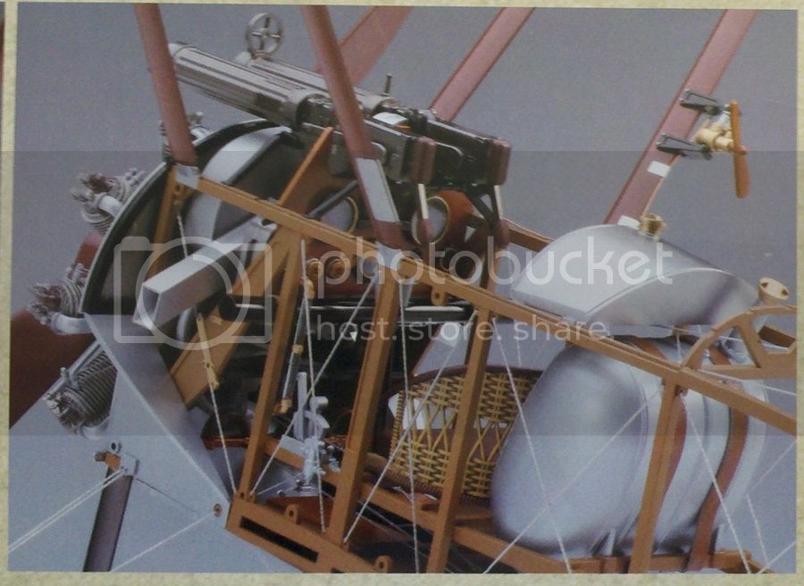
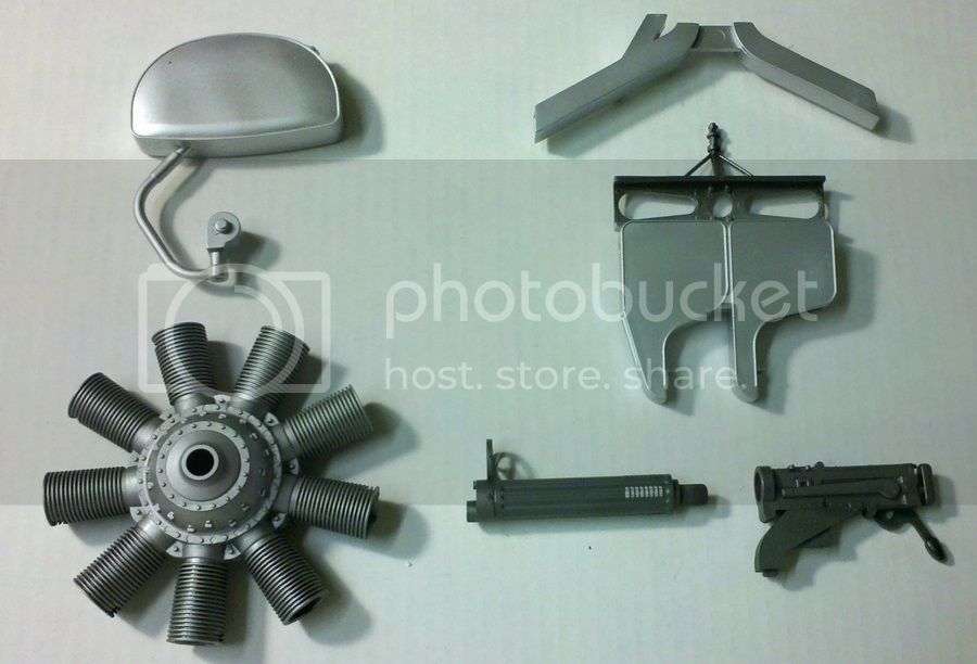
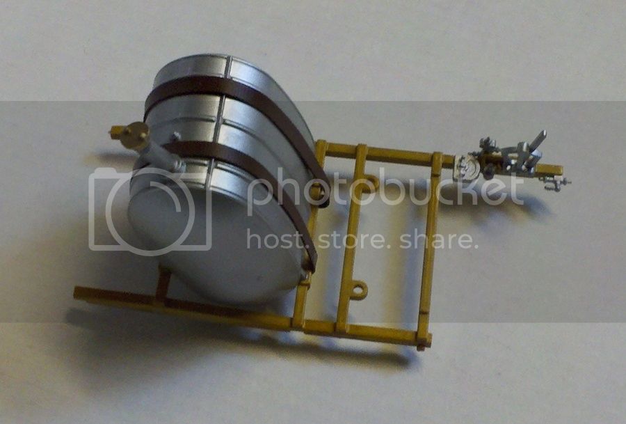
OK, where to start. One of the trees is silver plated and since this is and out of the box build, I wanted to use those plated parts as much as possible. But this was clearly going to be a problem with the fuel and oil tanks, as shown in this picture from the box sleeve:
and this picture of the actual fuel tank parts on the tree:
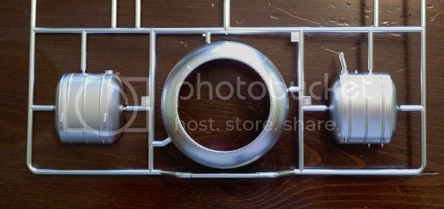
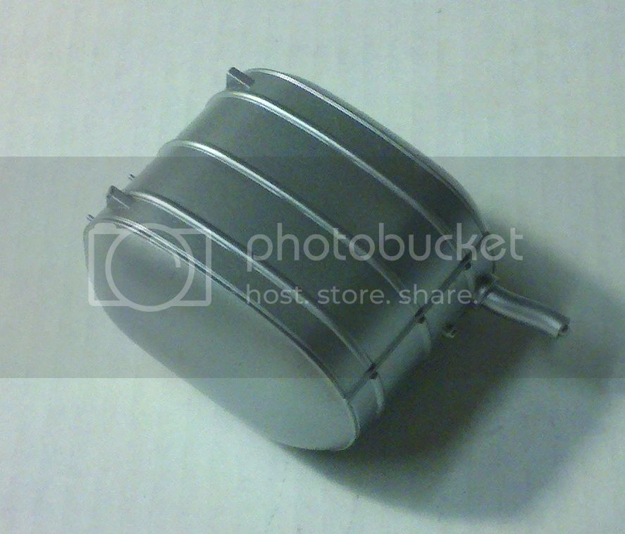
Note they're in two parts. This was true for the oil tank as well. And the fuel and oil filler caps have sprue attachment points that will show also. The problem is, this will all create seams and clean up spots that will remove the plating. My solution was to cut these parts off the sprue and dump them in brake fluid to strip off the plating, then glue them together and clean up the seams and repaint them with the Floquil Bright Silver. Not a perfect match, but close!
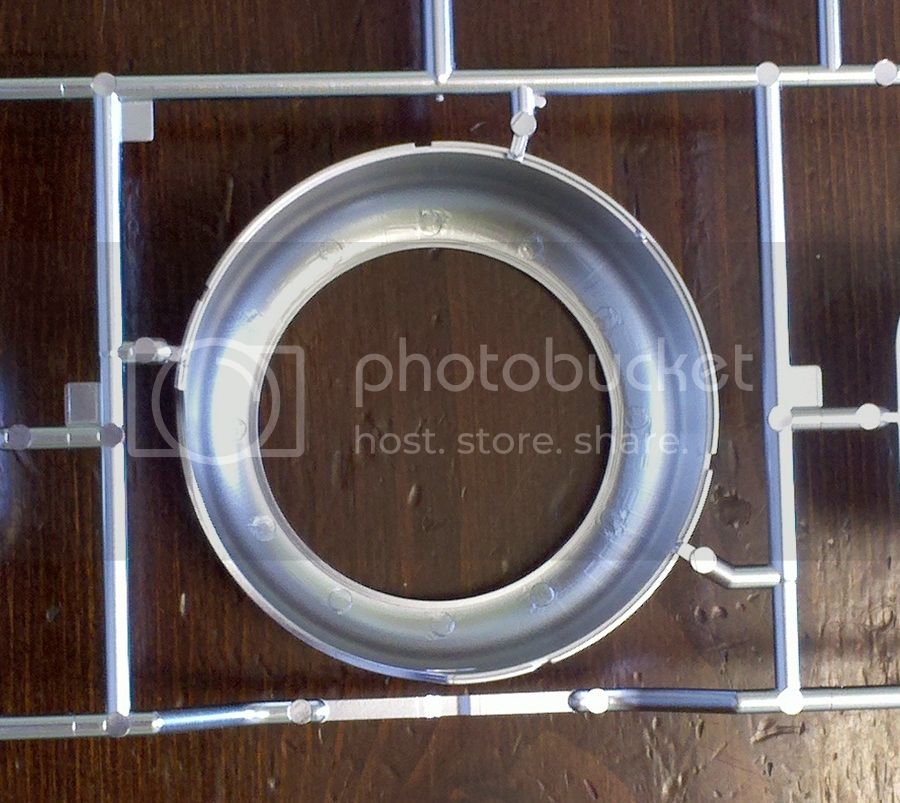
Luckily, the parts engineer was thinking when it came to the cowling, which is also plated and looks great. The sprue attachments here are on the bonding surface so, with careful cleanup, won't show where the plating is scraped off:
A number of metal parts, such as the guns, engine cylinders, cartridge ejection chutes, etc. are on sprues molded in black. Given that I was using Metalizer paint that has to be airbrushed, I cut those part off the sprues, glued them together, and cleaned them up before painting as well:
While I've gotten much further than this, this is the end of my post for now. Hopefully more tomorrow!
Michael
As I said: huge! And lots of parts! A lot of very nice detail, including instrument and Sopwith Aviation decals, rigging material in the form of silver thread, rubber hose material, a choice of covered or uncovered rudder, rubber tires (which I don't have a problem with in theory) and lots of open structure. Oh, and the control surfaces are linked to the stick and rudder bar and should operate if assembled correctly (we'll see)!
There are some flies in the ointment. There are no seat belts and no turnbuckles for the rigging. Also, the flying and landing wires should be a flat, aerodynamic cross section called "RAF wires" rather than round metal cable, so the rigging thread is technically incorrect. Still, that's what comes with the kit and that's what I'm going to use!
I'm painting with Tamiya paint throughout except for some of the metal colors, for which I'm using Floquil Bright Silver (as detailed below) and Model Master Metalizer.
OK, where to start. One of the trees is silver plated and since this is and out of the box build, I wanted to use those plated parts as much as possible. But this was clearly going to be a problem with the fuel and oil tanks, as shown in this picture from the box sleeve:

and this picture of the actual fuel tank parts on the tree:

Note they're in two parts. This was true for the oil tank as well. And the fuel and oil filler caps have sprue attachment points that will show also. The problem is, this will all create seams and clean up spots that will remove the plating. My solution was to cut these parts off the sprue and dump them in brake fluid to strip off the plating, then glue them together and clean up the seams and repaint them with the Floquil Bright Silver. Not a perfect match, but close!

Luckily, the parts engineer was thinking when it came to the cowling, which is also plated and looks great. The sprue attachments here are on the bonding surface so, with careful cleanup, won't show where the plating is scraped off:

A number of metal parts, such as the guns, engine cylinders, cartridge ejection chutes, etc. are on sprues molded in black. Given that I was using Metalizer paint that has to be airbrushed, I cut those part off the sprues, glued them together, and cleaned them up before painting as well:

While I've gotten much further than this, this is the end of my post for now. Hopefully more tomorrow!
Michael

Redhand

#522
Joined: January 20, 2013
KitMaker: 1,460 posts
AeroScale: 1,443 posts
Posted: Saturday, August 02, 2014 - 01:26 AM UTC
No wonder your "modeling muscles completely seized up"! What an audacious project and time commitment this is, even "out of the box!" The oil tank looks superb, BTW.
MichaelSatin
Joined: January 19, 2008
KitMaker: 3,909 posts
AeroScale: 2,904 posts
Posted: Saturday, August 02, 2014 - 02:16 AM UTC
Thanks Brian!
After getting the metal parts together and painted, it was time to consider my next move. I decided that with all the ribs that had to be attached to the wing panels, each with LOTs of cleanup to do,
I would build the wings before painting. For information's sake at this stage, I used the following Tamiya paint colors:
Light wood: Tamiya XF-78 Wood Deck Tan (an excellent wood color, in my opinion)
Light wood varnish: Tamiya clear yellow (airbrushed over all the light wood parts for a gloss varnished look)
Dark wood: Tamiya XF-52 Earth (in retrospect this is probably a bit too light)
Dark wood varnish: Tamiya clear orange
Now I know someone's going to ask, what did I use for the wood grain? The answer, I'm afraid, is that I copped out and didn't do any. The reason is that I had already sat on this one for too long and I didn't want to hold things up by getting out the oils and trying to add grain to all these bits. Still, with the varnish added, I think it all came out well. You'll see later.
By the way, when I'm using different paints than called for by the kit instructions, I usually make notes next to the kit paint list to show what I used instead. In the case of this kit, it is important to use the large color painting diagram Hasegawa includes since it actually has more color call outs than are in the instruction sheet. One small issue with the instructions is that since they molded the plastic in several colors, they often don't call out painting where the part should be the color it's molded in. Watch out for this!
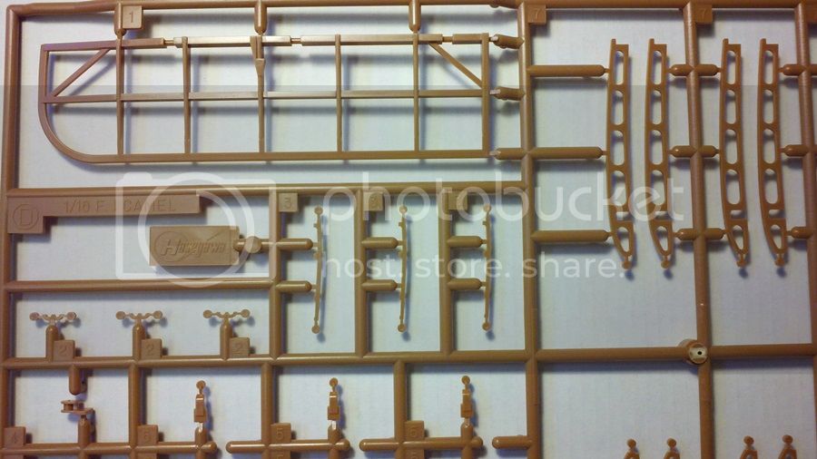
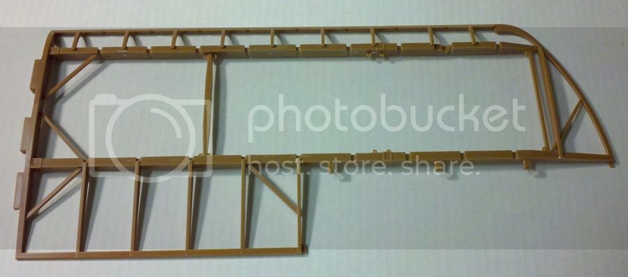
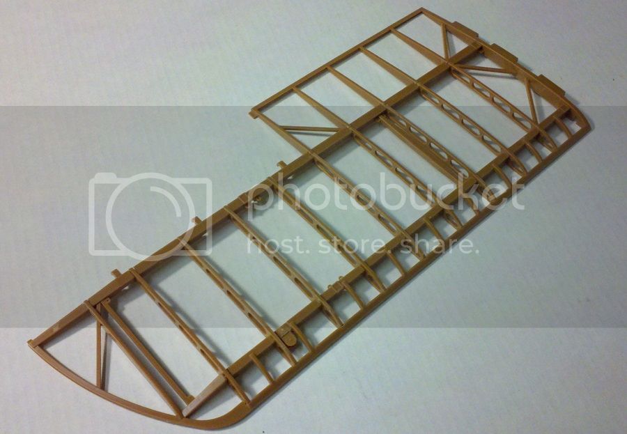
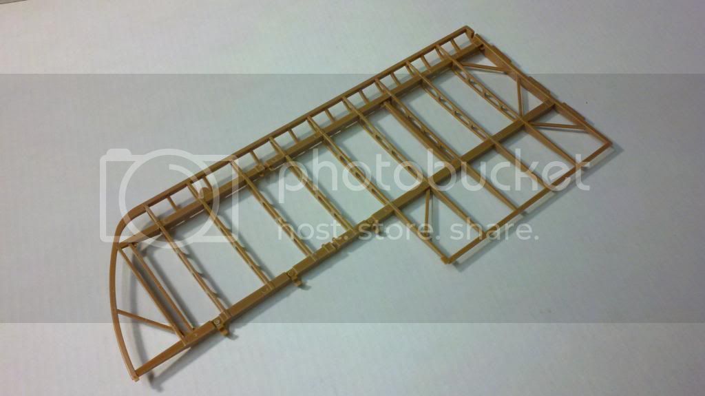
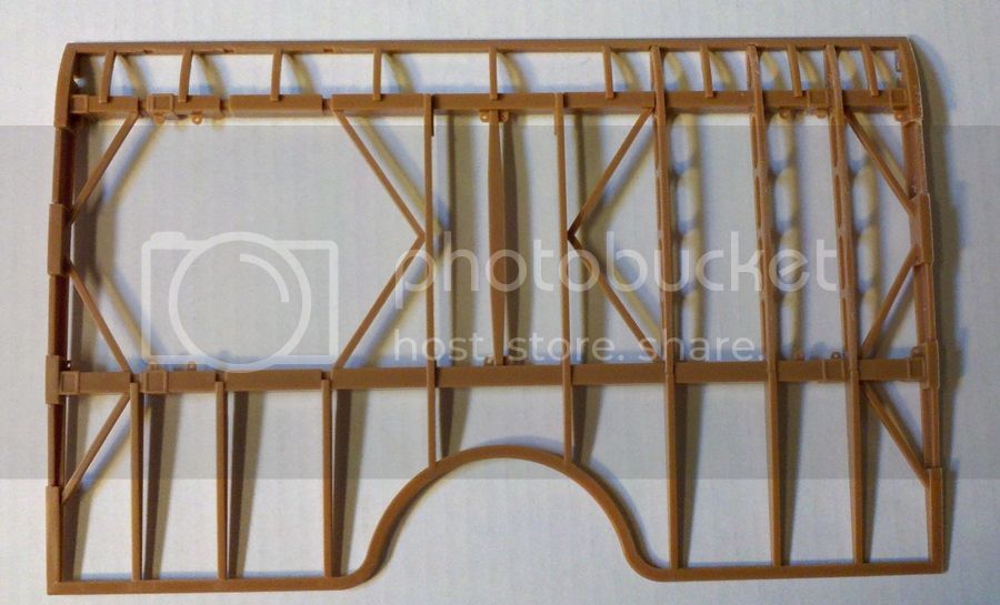
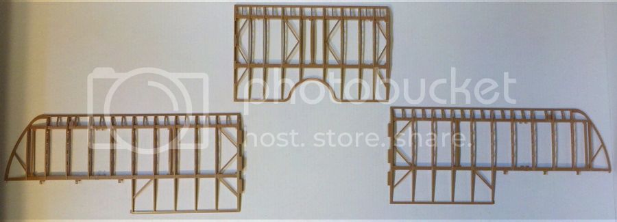
So, I started by cleaning up the wing panels (and there's a fair amount of clean up to do). Here's a top wing panel still on the tree:
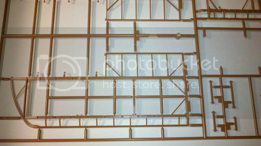
Here it is cleaned up and ready to start attaching ribs:
Here's the finished product ready to assemble into a whole wing:
Note the small part extending into the leading edge towards the wing tip. This is part D4 and each wing panel, top and bottom, has one. They are pulleys to lead the control wires around at a later stage. The instructions aren't entirely clear as to how they should be attached. The way I have it here is correct. Here's a view of the bottom of the wing panel so you can see it from that angle:
The top wing center section half assembled:
The top wing panels ready to go together:
And the top wing completely assembled:
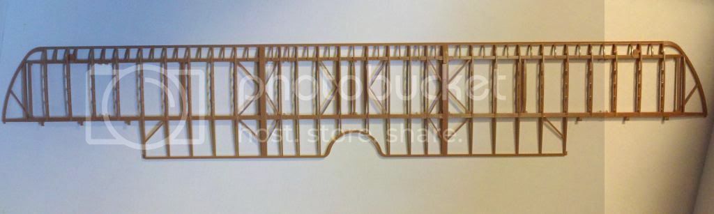
For the sake of relating size again, that sucker is 21 inches (53.34 cm) long and is, I believe, the largest dimension on the finished model. Whew!
That's it for the moment, more later depending on the honey-do list.
Michael
After getting the metal parts together and painted, it was time to consider my next move. I decided that with all the ribs that had to be attached to the wing panels, each with LOTs of cleanup to do,

I would build the wings before painting. For information's sake at this stage, I used the following Tamiya paint colors:
Light wood: Tamiya XF-78 Wood Deck Tan (an excellent wood color, in my opinion)
Light wood varnish: Tamiya clear yellow (airbrushed over all the light wood parts for a gloss varnished look)
Dark wood: Tamiya XF-52 Earth (in retrospect this is probably a bit too light)
Dark wood varnish: Tamiya clear orange
Now I know someone's going to ask, what did I use for the wood grain? The answer, I'm afraid, is that I copped out and didn't do any. The reason is that I had already sat on this one for too long and I didn't want to hold things up by getting out the oils and trying to add grain to all these bits. Still, with the varnish added, I think it all came out well. You'll see later.
By the way, when I'm using different paints than called for by the kit instructions, I usually make notes next to the kit paint list to show what I used instead. In the case of this kit, it is important to use the large color painting diagram Hasegawa includes since it actually has more color call outs than are in the instruction sheet. One small issue with the instructions is that since they molded the plastic in several colors, they often don't call out painting where the part should be the color it's molded in. Watch out for this!
So, I started by cleaning up the wing panels (and there's a fair amount of clean up to do). Here's a top wing panel still on the tree:

Here it is cleaned up and ready to start attaching ribs:

Here's the finished product ready to assemble into a whole wing:

Note the small part extending into the leading edge towards the wing tip. This is part D4 and each wing panel, top and bottom, has one. They are pulleys to lead the control wires around at a later stage. The instructions aren't entirely clear as to how they should be attached. The way I have it here is correct. Here's a view of the bottom of the wing panel so you can see it from that angle:

The top wing center section half assembled:

The top wing panels ready to go together:

And the top wing completely assembled:

For the sake of relating size again, that sucker is 21 inches (53.34 cm) long and is, I believe, the largest dimension on the finished model. Whew!
That's it for the moment, more later depending on the honey-do list.
Michael
ludwig113

Joined: February 05, 2008
KitMaker: 1,381 posts
AeroScale: 1,110 posts

Posted: Saturday, August 02, 2014 - 02:25 AM UTC
looking great, I've always wanted to do one of those, will def. watch your progress.
paul
paul
MichaelSatin
Joined: January 19, 2008
KitMaker: 3,909 posts
AeroScale: 2,904 posts
Posted: Saturday, August 02, 2014 - 04:00 AM UTC
Thanks Paul!
Forgot something folks. The wing ribs have small knock out pins on their leading edge that need to be removed:
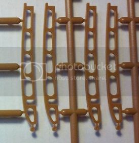
Be careful cleaning that area up, the ribs have a small ledge and notch on the front that is supposed to be there to fit into the corresponding area on the wing:
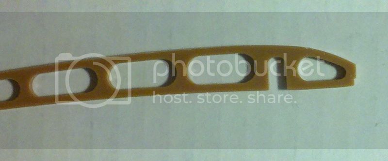
It's easy to sand/file that off when you're cleaning up the parts, so forewarned is forearmed!
Michael
MichaelSatin
Joined: January 19, 2008
KitMaker: 3,909 posts
AeroScale: 2,904 posts
Posted: Saturday, August 02, 2014 - 04:49 AM UTC
Here are some painting pictures. First, this is the inside of parts B4 and B5, cockpit side panels. Since they have framework molded in I painted the light wood color first, masked off the frames with thin pieces of making tape, then the dark wood:
I believe these parts are actually optional, though the instructions don't say so. I think you can leave them off if you want a better view of the cockpit when completed. I think it's also possible to take these and the engine compartment panels on and off if you're careful. I'll give it a try when I get to that point and let you know.
Here is sprue E, a sprue with several parts in both light and dark wood, with the colors on but not the clear yellow and orange varnishes:
Sorry about the picture quality and shadows, should have taken a better shot.
And here's the same sprue with clear yellow varnish on the light wood and the clear orange on the dark:
I think those tinted clear varnishes really make a nice difference. Glad Tamiya makes them in those colors!
Michael

I believe these parts are actually optional, though the instructions don't say so. I think you can leave them off if you want a better view of the cockpit when completed. I think it's also possible to take these and the engine compartment panels on and off if you're careful. I'll give it a try when I get to that point and let you know.
Here is sprue E, a sprue with several parts in both light and dark wood, with the colors on but not the clear yellow and orange varnishes:

Sorry about the picture quality and shadows, should have taken a better shot.
And here's the same sprue with clear yellow varnish on the light wood and the clear orange on the dark:

I think those tinted clear varnishes really make a nice difference. Glad Tamiya makes them in those colors!
Michael
MichaelSatin
Joined: January 19, 2008
KitMaker: 3,909 posts
AeroScale: 2,904 posts
Posted: Saturday, August 02, 2014 - 12:11 PM UTC
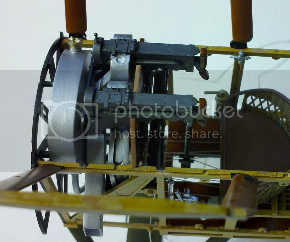
Rounding out the day with some random pics as actual construction begins. First, this is a bottom wing panel and the horizontal stabilizer fully painted, including the molded on metal brackets, hinges, etc. which I painted using Tamiya XF-56 Metallic Gray:
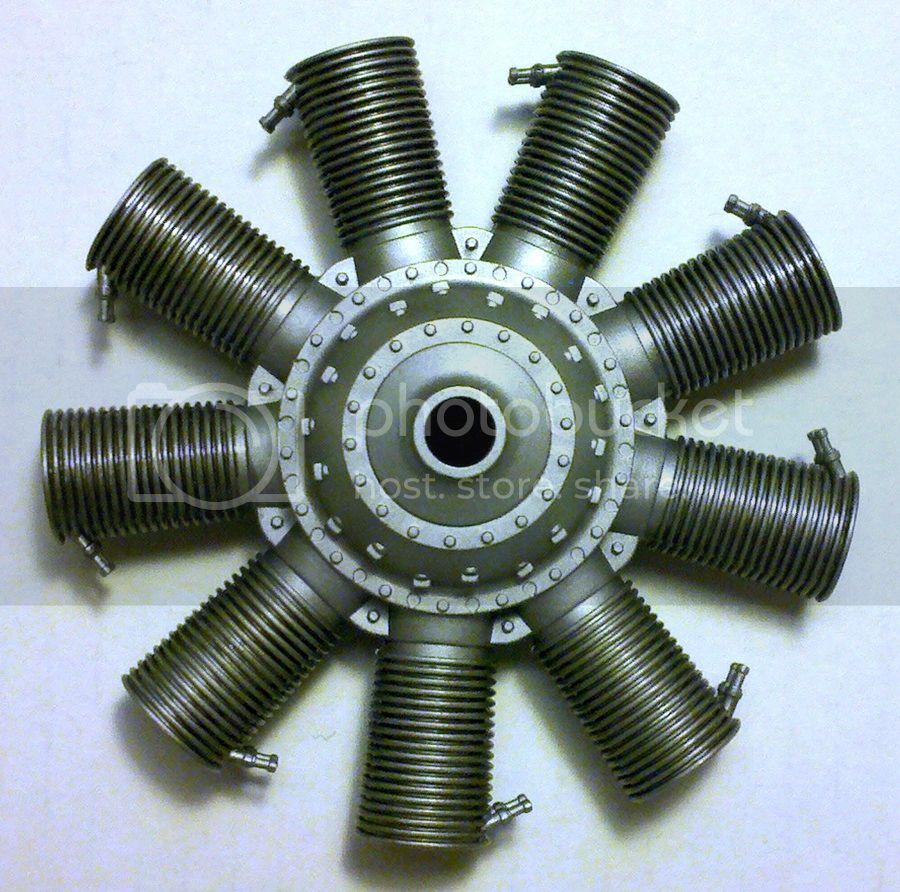
Next, here's the main engine washed with Tamiya Smoke to bring out the cooling fins and with the spark plugs glued in. They seat nicely at the correct angle if you use a tweezers to set them in place prior to gluing. The instructions also have a diagram showing how they should look:
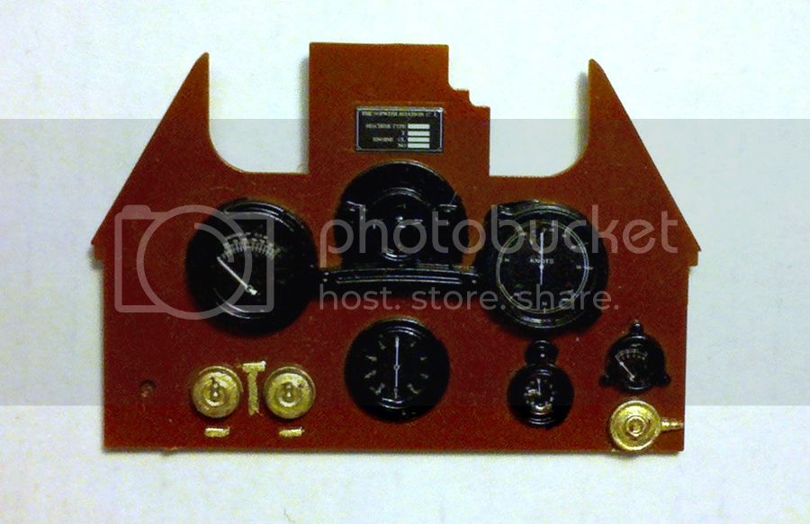
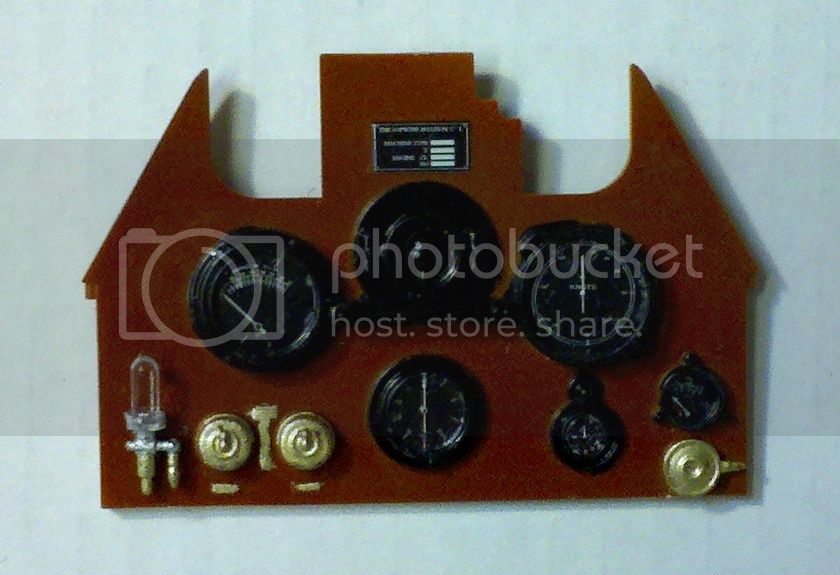
Finally here's the instrument panel with the decals in place but not the instrument glass or a couple of other parts to be added. The decals fit nicely and settle in with some Micro-Sol, but are a bit more fragile than you think so be careful if you have to move them around:
By the way, I used Tamiya X-31 Titan Gold for the brass parts. It matches Testors Metalizer Brass fairly well for touch up too.
Michael

Next, here's the main engine washed with Tamiya Smoke to bring out the cooling fins and with the spark plugs glued in. They seat nicely at the correct angle if you use a tweezers to set them in place prior to gluing. The instructions also have a diagram showing how they should look:

Finally here's the instrument panel with the decals in place but not the instrument glass or a couple of other parts to be added. The decals fit nicely and settle in with some Micro-Sol, but are a bit more fragile than you think so be careful if you have to move them around:

By the way, I used Tamiya X-31 Titan Gold for the brass parts. It matches Testors Metalizer Brass fairly well for touch up too.
Michael
MichaelSatin
Joined: January 19, 2008
KitMaker: 3,909 posts
AeroScale: 2,904 posts
Posted: Monday, August 04, 2014 - 04:19 AM UTC
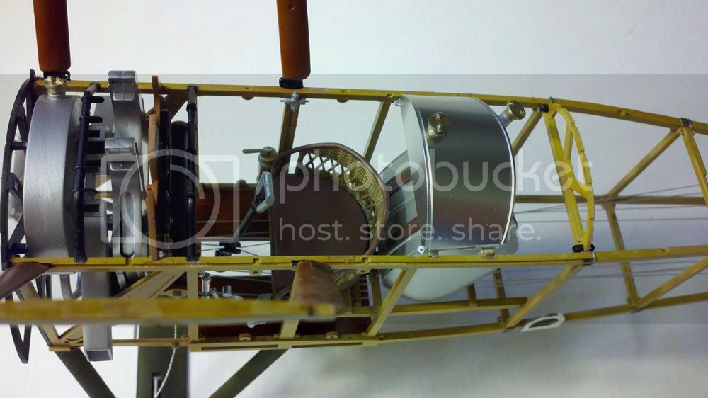
Couple of updates. Here's the completed engine (actually the first steps in the formal order of construction):
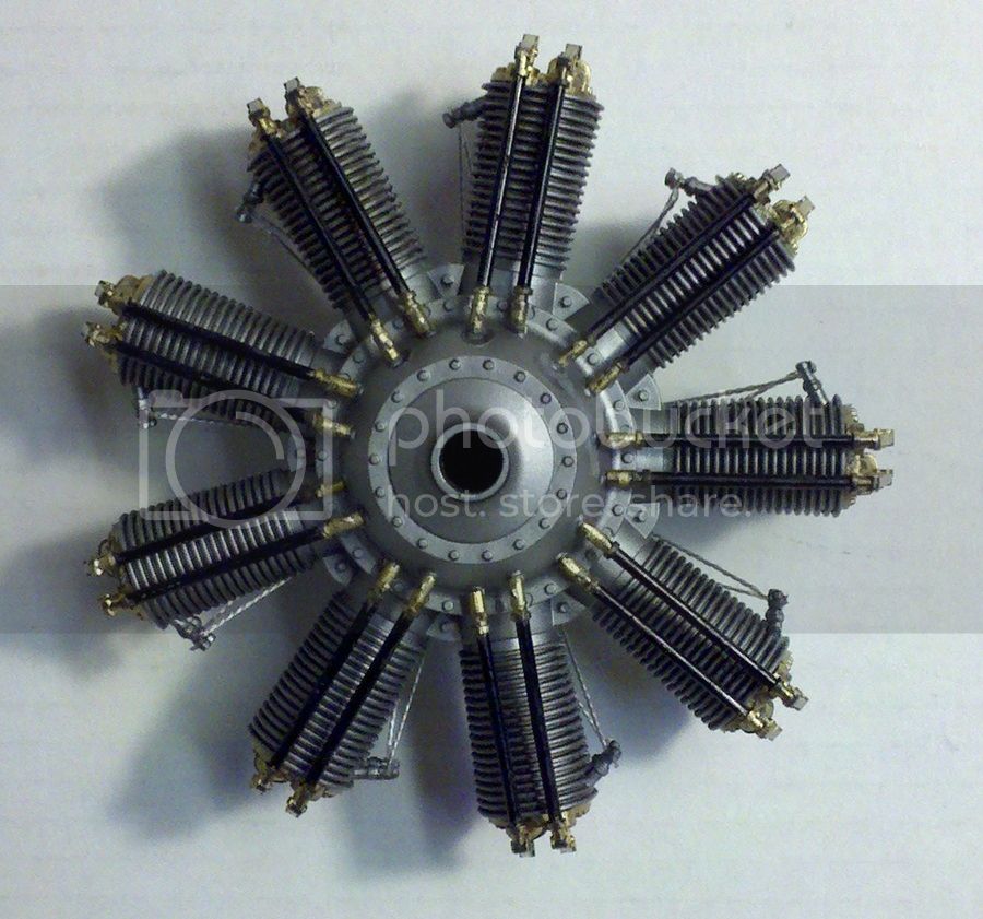

The engine is painted according to the kit instructions. Rigging the spark plug wires was interesting. They utilize the same line as will be used for the rigging later. I found that about a 55mm length is what you need for each cylinder. First I squirted the back of the engine and the pugs with accelerator (I find it still works even when it has dried). Then I held the ends of the 55mm length of line together and looped it around the two pips on the back of the engine and applied a bit of cyano glue with a piece of wire. Once that held, I wound the end around one of the plugs and used a drop of cyano with the wire again then repeated with the other plug. I found that if I coated the excess thread with cyano at the same time, cutting it was easier.
Here is the completed instrument panel with the lenses and fuel indicator in place. I used Gator Glue on the lenses, good old white glue like Elmers or Testors clear parts cement would probably have been a better choice.
That's about it for now, this blog has caught up with where I actually am in building the beast. More as I get further along!
Michael


The engine is painted according to the kit instructions. Rigging the spark plug wires was interesting. They utilize the same line as will be used for the rigging later. I found that about a 55mm length is what you need for each cylinder. First I squirted the back of the engine and the pugs with accelerator (I find it still works even when it has dried). Then I held the ends of the 55mm length of line together and looped it around the two pips on the back of the engine and applied a bit of cyano glue with a piece of wire. Once that held, I wound the end around one of the plugs and used a drop of cyano with the wire again then repeated with the other plug. I found that if I coated the excess thread with cyano at the same time, cutting it was easier.
Here is the completed instrument panel with the lenses and fuel indicator in place. I used Gator Glue on the lenses, good old white glue like Elmers or Testors clear parts cement would probably have been a better choice.

That's about it for now, this blog has caught up with where I actually am in building the beast. More as I get further along!
Michael
wing_nut
Joined: June 02, 2006
KitMaker: 1,212 posts
AeroScale: 468 posts
Posted: Tuesday, August 05, 2014 - 12:17 AM UTC
The engine looks great. Can almost smell the castor oil.

Merlin

#017

Joined: June 11, 2003
KitMaker: 17,582 posts
AeroScale: 12,795 posts

Posted: Tuesday, August 05, 2014 - 08:03 AM UTC
Nice work so far Michael! 
This is going to be an epic build.
All the best
Rowan
This is going to be an epic build.
All the best
Rowan

MichaelSatin
Joined: January 19, 2008
KitMaker: 3,909 posts
AeroScale: 2,904 posts
Posted: Saturday, August 09, 2014 - 01:28 PM UTC
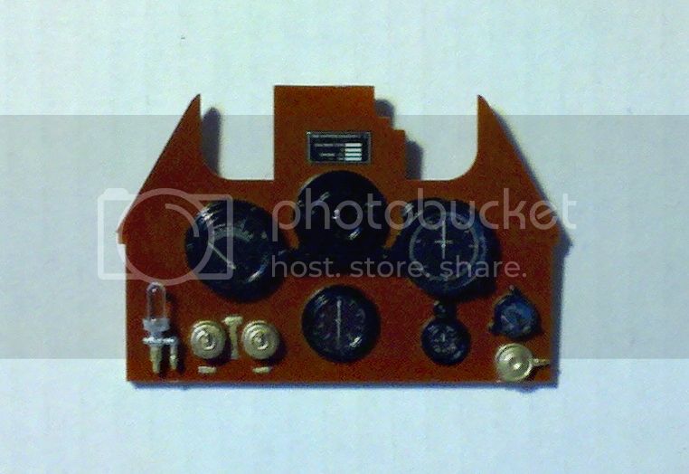
OK, today's update. First, here's a new shot of the instrument panel showing that the Gator Glue dried quite clear and all is well. In case you were worried. Well, I was!
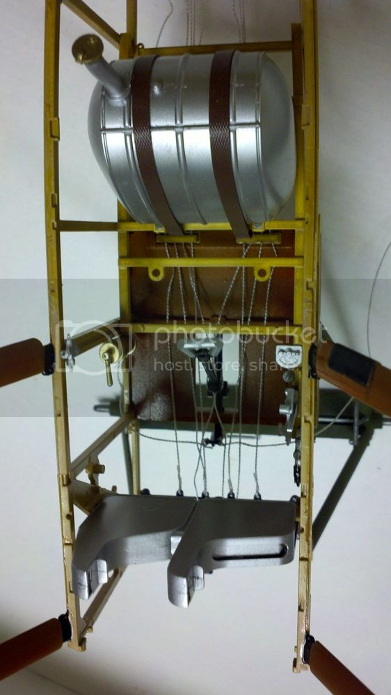
Next up, the cockpit. First I put together the fuel tank and various controls and bits. The leatherette straps that Hasegawa provide are quite nice and make for a good look:
Then came some REAL fun. As I mentioned before, the controls actually hook up to the control surfaces and operate, if done carefully. At this stage it's time to rig the controls in the cockpit. First, a scan of the instructions:
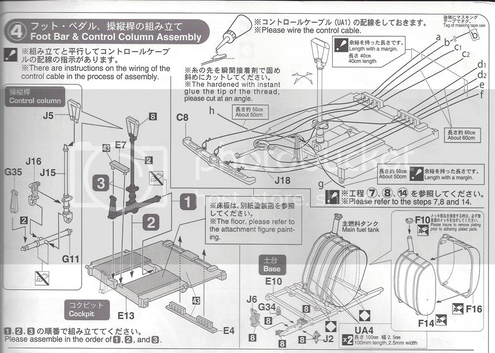
It all looks fairly clear there, if you study it carefully. But, no surprise, getting it all together without tangling it all up is a whole other thing! Oh, and as you're cutting the pieces of line, remember the carpenter's adage: Measure twice, cut once. I don't know if Hasegawa provides us with excess line, but I don't want to take the chance. The measurements they provide do take excess for tying off into account, so that's good news.
First off, note the way the line goes through the base of the control stick. This looks bad enough, but it's even worse in practice. You might want to rig the line through parts J15 and J16 before you actually glue them together, if you think you can keep them clear while you assemble. DON'T glue the lines in, you'll want to be able to pull them back and forth as you go forward. Then put the plastic parts of the controls together as shown and let it all dry. If you do it as shown in the instructions and used glue sparingly (I use Weld-On, or whatever it's called these days), it's not hard to ensure that it all moves when dried.
Now I'm speaking from experience here, I had a lot of un-rigging to do before I came up with a solution for keeping all the lines straight:
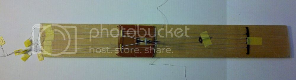
My advice is, start with the rudder bar (part C8). Attach your lines (a,b,e and f) to that, then tape it down on your flat surface. I strongly suggest a flat piece of wood or glass that you can move around, since you'll have to maneuver a bit to get it all done. Thread the rudder lines through the guide (part E4) one by one, label them as suggested with small pieces of tape, and tape them down on your flat surface behind the completed cockpit floor as shown. I kept the floor loose so I could move it back and forth, but you might want to tape it down too.
After you have the rudder bar rigged up, run the lines from the control stick base (c1, c2 are one piece of line as are d1 and d2) through part J18. Note how they go in the top and out the bottom of J18 and which part of the lines go through which holes in the guide (E4 again).
Finally attach lines g and h to part G35 and let them fall to the sides. Again, note which lines they go over and which ones they go under. Careful study of the instructions is very important here.
Hasegawa includes large, full size plan drawings of the rigging showing where all the lines will end up. It's a good idea to have these as handy as you can (they're big) so you can see where the lines you're installing will go.
Hasegawa suggests coating the end of each line in cyano glue to make it stiff. This does work, by the way, though if the stiff end is too long it will make it that much harder to thread c1 and d2 through the base of the stick (J15 and J16) after you've glued them together.
How all this is going to attach to the fuselage and stay straight I don't know, I'll fill you in when I find out.
This was a very quick and dirty solution. If anyone has a better idea, feel free to post it here! More soon, I hope!
Michael

Next up, the cockpit. First I put together the fuel tank and various controls and bits. The leatherette straps that Hasegawa provide are quite nice and make for a good look:

Then came some REAL fun. As I mentioned before, the controls actually hook up to the control surfaces and operate, if done carefully. At this stage it's time to rig the controls in the cockpit. First, a scan of the instructions:

It all looks fairly clear there, if you study it carefully. But, no surprise, getting it all together without tangling it all up is a whole other thing! Oh, and as you're cutting the pieces of line, remember the carpenter's adage: Measure twice, cut once. I don't know if Hasegawa provides us with excess line, but I don't want to take the chance. The measurements they provide do take excess for tying off into account, so that's good news.
First off, note the way the line goes through the base of the control stick. This looks bad enough, but it's even worse in practice. You might want to rig the line through parts J15 and J16 before you actually glue them together, if you think you can keep them clear while you assemble. DON'T glue the lines in, you'll want to be able to pull them back and forth as you go forward. Then put the plastic parts of the controls together as shown and let it all dry. If you do it as shown in the instructions and used glue sparingly (I use Weld-On, or whatever it's called these days), it's not hard to ensure that it all moves when dried.
Now I'm speaking from experience here, I had a lot of un-rigging to do before I came up with a solution for keeping all the lines straight:

My advice is, start with the rudder bar (part C8). Attach your lines (a,b,e and f) to that, then tape it down on your flat surface. I strongly suggest a flat piece of wood or glass that you can move around, since you'll have to maneuver a bit to get it all done. Thread the rudder lines through the guide (part E4) one by one, label them as suggested with small pieces of tape, and tape them down on your flat surface behind the completed cockpit floor as shown. I kept the floor loose so I could move it back and forth, but you might want to tape it down too.
After you have the rudder bar rigged up, run the lines from the control stick base (c1, c2 are one piece of line as are d1 and d2) through part J18. Note how they go in the top and out the bottom of J18 and which part of the lines go through which holes in the guide (E4 again).
Finally attach lines g and h to part G35 and let them fall to the sides. Again, note which lines they go over and which ones they go under. Careful study of the instructions is very important here.
Hasegawa includes large, full size plan drawings of the rigging showing where all the lines will end up. It's a good idea to have these as handy as you can (they're big) so you can see where the lines you're installing will go.
Hasegawa suggests coating the end of each line in cyano glue to make it stiff. This does work, by the way, though if the stiff end is too long it will make it that much harder to thread c1 and d2 through the base of the stick (J15 and J16) after you've glued them together.
How all this is going to attach to the fuselage and stay straight I don't know, I'll fill you in when I find out.
This was a very quick and dirty solution. If anyone has a better idea, feel free to post it here! More soon, I hope!
Michael
MichaelSatin
Joined: January 19, 2008
KitMaker: 3,909 posts
AeroScale: 2,904 posts
Posted: Sunday, August 10, 2014 - 11:43 AM UTC
OK, today's progress report.
Today was fuselage assembly day. After carefully studying the instructions, I started by putting together the tail skid assembly. This will need to swivel and move up and down to work right, so you want it together and dry before trapping it in the fuselage halves. I also put together the aft cockpit former (parts L6 x2 and E5) together at this time as well as the rudder bar foot straps (cut from the same leatherette piece as the fuel tank straps) and the landing gear spreader bar (parts N4 and 5).
A small digression on the gear spreader bar. Technically, this part is incorrect. Sopwith landing gear shock absorbing was accomplished by splitting the gear axle and allowing the right and left halves to swivel up and down, tied in by bungie cords. That's why when you see pictures of Sopwith aircraft on the ground, their wheels are cockeyed (not vertical). Hasegawa molded the axles in halves correctly, but fixed them horizontally. As it's all molded together, this would be hard to correct and, as I'm building this out of the box, I didn't. But I thought I'd let you know.
Right, back to reality. While the above was all setting up, I added some small cockpit bits (parts J1, G12 and Q3) to the left and right fuselage halves (parts A1 and A2) which Hasegawa happily molded as large one part assemblies. I then glued the completed fuel tank base to the right side.
Now it's time to glue in the cockpit floor. This means removing it and it's associated control rigging from the jig I made yesterday. First I taped together all the lines leading aft to attempt to keep them corralled. Then I carefully removed the tape holding them to the jig, as well as the tape holding down the rudder bar and part J18 (still not sure what to call that). I then (carefully again!) glued the floor into the right fuselage half, making sure the aft lines lead aft and the rudder bar and J18 lead forward and didn't get tangled up. Here's what the right fuselage half looked like at this point:
And here's a closer look at the cockpit area:
Take a deep breath. Now, get ready to add the right fuselage half, being sure to trap the landing gear spreader bar and the tail skid assembly (don't glue this) as well as keeping the control rigging clear. About 5 hands help at this point. Forward end:
Aft end:
The floor and fuel tank base actually line up pretty well, the attachment points are pretty precise.
Right, go have an adult beverage to steady your nerves. Then, back at it! Add the upper (parts C3, 1, 13 and 12) and lower (parts B1, 6, 8, 9 and 7) framework parts. Study the instruction diagrams closely, they have attachments for later parts molded in and you want to be sure to position them correctly. This goes for rigging anchor part J14 at the tail end as well. Again, keep those control rigging lines clear! Here's what it looks like all closed up:
Finally, use elastic ("rubber"? Love those Japanese instructions!) thread UA2 to tie up the tail skid. I used about 50mm all told but am concerned the 20mm total length shown in the instructions may be too little. We'll see how it looks when the tail feathers are added to weigh it down a little more.
I have actually moved on a bit to add the cartridge boxes with part J18 and the rudder bar attached to try to start cutting down on my control rigging woes, and it seems to have worked, but I'm too wiped to take pics now. Soon though! For now, more adult beverage for me. Cheers!
Michael
Today was fuselage assembly day. After carefully studying the instructions, I started by putting together the tail skid assembly. This will need to swivel and move up and down to work right, so you want it together and dry before trapping it in the fuselage halves. I also put together the aft cockpit former (parts L6 x2 and E5) together at this time as well as the rudder bar foot straps (cut from the same leatherette piece as the fuel tank straps) and the landing gear spreader bar (parts N4 and 5).
A small digression on the gear spreader bar. Technically, this part is incorrect. Sopwith landing gear shock absorbing was accomplished by splitting the gear axle and allowing the right and left halves to swivel up and down, tied in by bungie cords. That's why when you see pictures of Sopwith aircraft on the ground, their wheels are cockeyed (not vertical). Hasegawa molded the axles in halves correctly, but fixed them horizontally. As it's all molded together, this would be hard to correct and, as I'm building this out of the box, I didn't. But I thought I'd let you know.
Right, back to reality. While the above was all setting up, I added some small cockpit bits (parts J1, G12 and Q3) to the left and right fuselage halves (parts A1 and A2) which Hasegawa happily molded as large one part assemblies. I then glued the completed fuel tank base to the right side.
Now it's time to glue in the cockpit floor. This means removing it and it's associated control rigging from the jig I made yesterday. First I taped together all the lines leading aft to attempt to keep them corralled. Then I carefully removed the tape holding them to the jig, as well as the tape holding down the rudder bar and part J18 (still not sure what to call that). I then (carefully again!) glued the floor into the right fuselage half, making sure the aft lines lead aft and the rudder bar and J18 lead forward and didn't get tangled up. Here's what the right fuselage half looked like at this point:

And here's a closer look at the cockpit area:

Take a deep breath. Now, get ready to add the right fuselage half, being sure to trap the landing gear spreader bar and the tail skid assembly (don't glue this) as well as keeping the control rigging clear. About 5 hands help at this point. Forward end:

Aft end:

The floor and fuel tank base actually line up pretty well, the attachment points are pretty precise.
Right, go have an adult beverage to steady your nerves. Then, back at it! Add the upper (parts C3, 1, 13 and 12) and lower (parts B1, 6, 8, 9 and 7) framework parts. Study the instruction diagrams closely, they have attachments for later parts molded in and you want to be sure to position them correctly. This goes for rigging anchor part J14 at the tail end as well. Again, keep those control rigging lines clear! Here's what it looks like all closed up:

Finally, use elastic ("rubber"? Love those Japanese instructions!) thread UA2 to tie up the tail skid. I used about 50mm all told but am concerned the 20mm total length shown in the instructions may be too little. We'll see how it looks when the tail feathers are added to weigh it down a little more.

I have actually moved on a bit to add the cartridge boxes with part J18 and the rudder bar attached to try to start cutting down on my control rigging woes, and it seems to have worked, but I'm too wiped to take pics now. Soon though! For now, more adult beverage for me. Cheers!
Michael
MichaelSatin
Joined: January 19, 2008
KitMaker: 3,909 posts
AeroScale: 2,904 posts
Posted: Monday, August 11, 2014 - 12:39 PM UTC
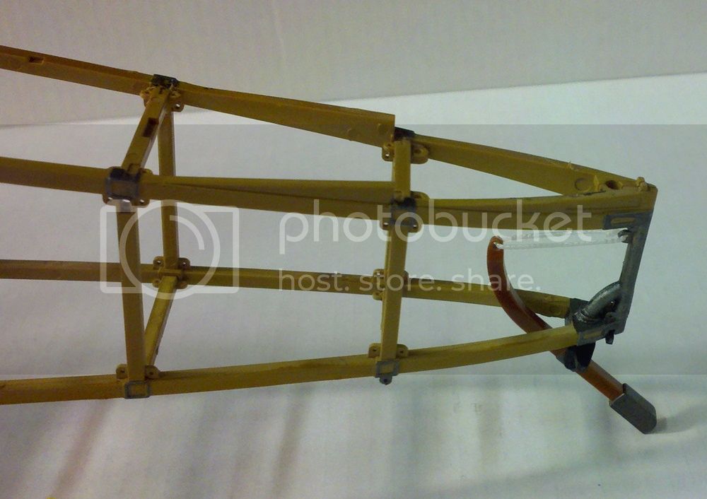
OK, as promised here are a couple of shots with the rudder bar and J18 (an anchor for the elevator controls?) mounted. This did seem to help a lot!
Here's the cockpit from above. Remember, all those lines leading aft still have no control surfaces to connect to, that comes later.
And here's the rudder bar and J18 from the front. The shaft protruding from J18 will connect to a large forward fuselage former in a couple of steps to hold everything steady.
Can hardly wait to see what comes next!
Michael
Here's the cockpit from above. Remember, all those lines leading aft still have no control surfaces to connect to, that comes later.

And here's the rudder bar and J18 from the front. The shaft protruding from J18 will connect to a large forward fuselage former in a couple of steps to hold everything steady.

Can hardly wait to see what comes next!
Michael
MichaelSatin
Joined: January 19, 2008
KitMaker: 3,909 posts
AeroScale: 2,904 posts
Posted: Saturday, August 16, 2014 - 10:55 AM UTC
And, here's what come's next!
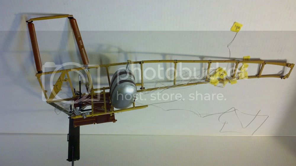
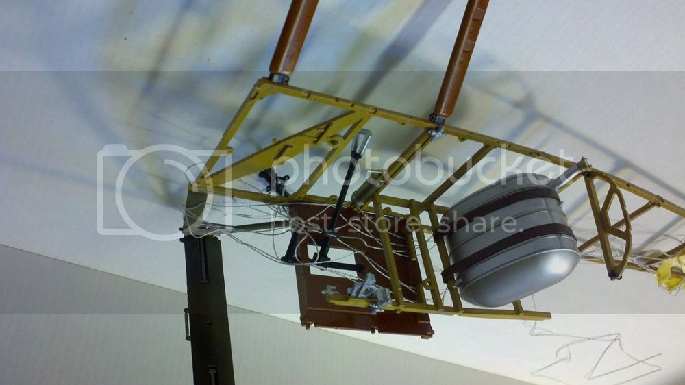
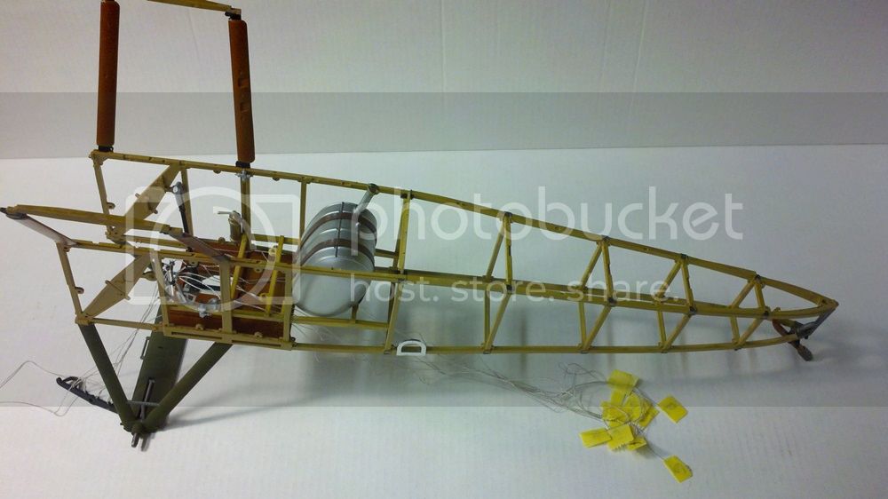
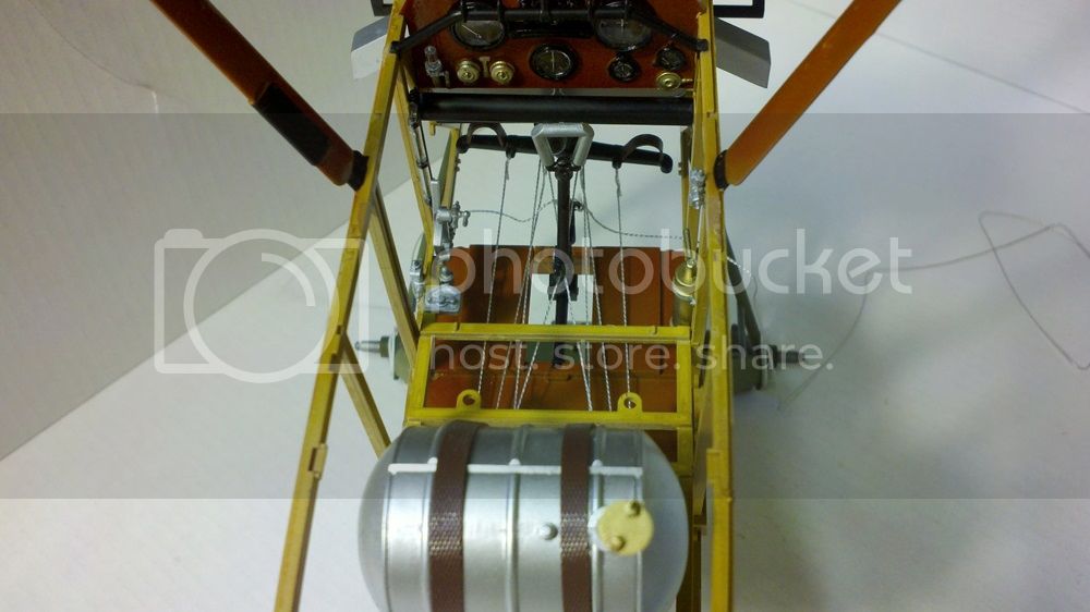
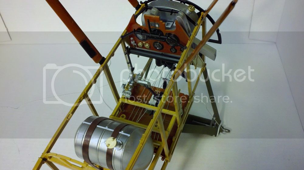
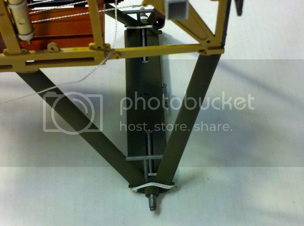
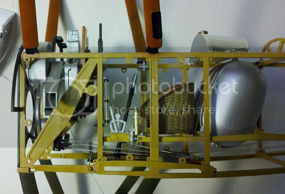
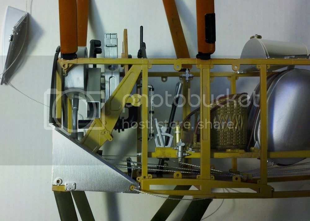
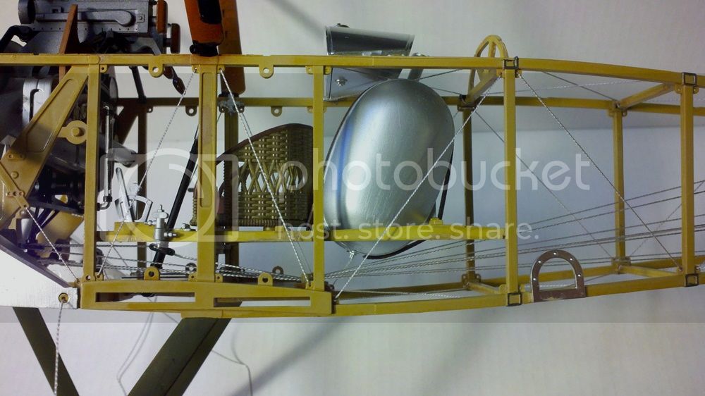
The next moves are to add the oil tank to a forward former/bulkhead piece which, when glued to the front of the fuselage, will also be used to finally nail down part J18, making it a stationary anchor for the elevator control lines. Here it is from the front and above:
And here it is from below:
J18 is the thin black rod running from under the rudder bar to the bottom of that forward former.
In this step you also add the instrument panel and gun mounts:
I had to use a piece of masking tape to pull in the fuselage sides a bit to ensure a tight fit. No real problem.
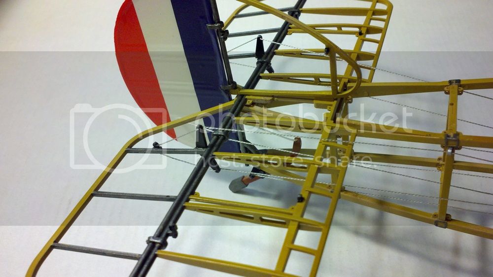
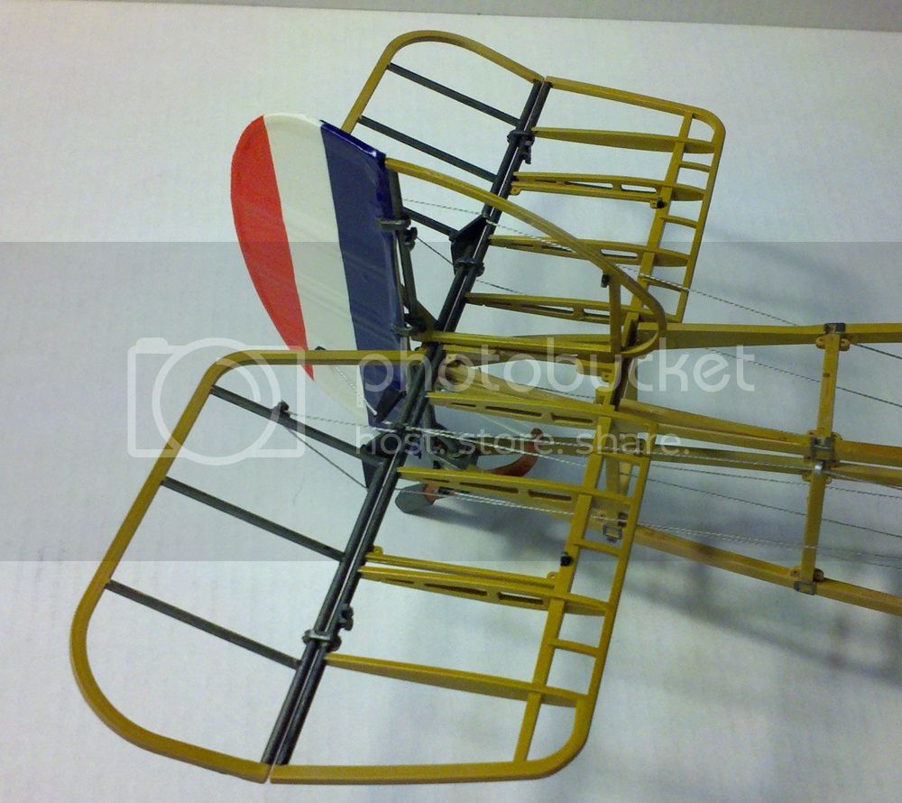
The next step finds us putting together the horizontal and vertical tail pieces, including elevators and rudder. Be careful when gluing the hinges in and make sure you allow it to dry thoroughly while moving the elevator and rudder occasionally to ensure free movement.
When these are glued to the fuselage, the instructions show to cut off a molded on block on the top of the fuselage to allow things to move. This is so if you don't want to go that route, everything will remain rigidly in a neutral position. I cut it off mine as I want to see if I can make everything work.
Here's something to remember (I almost forgot). The kit comes with a solid rudder and a framework one. If you use the solid one, there are large red/white/blue striped decals to go on it. Put these on BEFORE you rig the rudder or you'll have to slice the decals. It's possible to put the decals on after you've put the rigging anchors and control arms on, even after you mount the rudder to the fin, but not once it's rigged.
Rigging the tail control surfaces next. I'll let you know!
Michael
The next moves are to add the oil tank to a forward former/bulkhead piece which, when glued to the front of the fuselage, will also be used to finally nail down part J18, making it a stationary anchor for the elevator control lines. Here it is from the front and above:

And here it is from below:

J18 is the thin black rod running from under the rudder bar to the bottom of that forward former.
In this step you also add the instrument panel and gun mounts:

I had to use a piece of masking tape to pull in the fuselage sides a bit to ensure a tight fit. No real problem.
The next step finds us putting together the horizontal and vertical tail pieces, including elevators and rudder. Be careful when gluing the hinges in and make sure you allow it to dry thoroughly while moving the elevator and rudder occasionally to ensure free movement.
When these are glued to the fuselage, the instructions show to cut off a molded on block on the top of the fuselage to allow things to move. This is so if you don't want to go that route, everything will remain rigidly in a neutral position. I cut it off mine as I want to see if I can make everything work.
Here's something to remember (I almost forgot). The kit comes with a solid rudder and a framework one. If you use the solid one, there are large red/white/blue striped decals to go on it. Put these on BEFORE you rig the rudder or you'll have to slice the decals. It's possible to put the decals on after you've put the rigging anchors and control arms on, even after you mount the rudder to the fin, but not once it's rigged.
Rigging the tail control surfaces next. I'll let you know!
Michael
MichaelSatin
Joined: January 19, 2008
KitMaker: 3,909 posts
AeroScale: 2,904 posts
Posted: Sunday, August 17, 2014 - 06:01 AM UTC
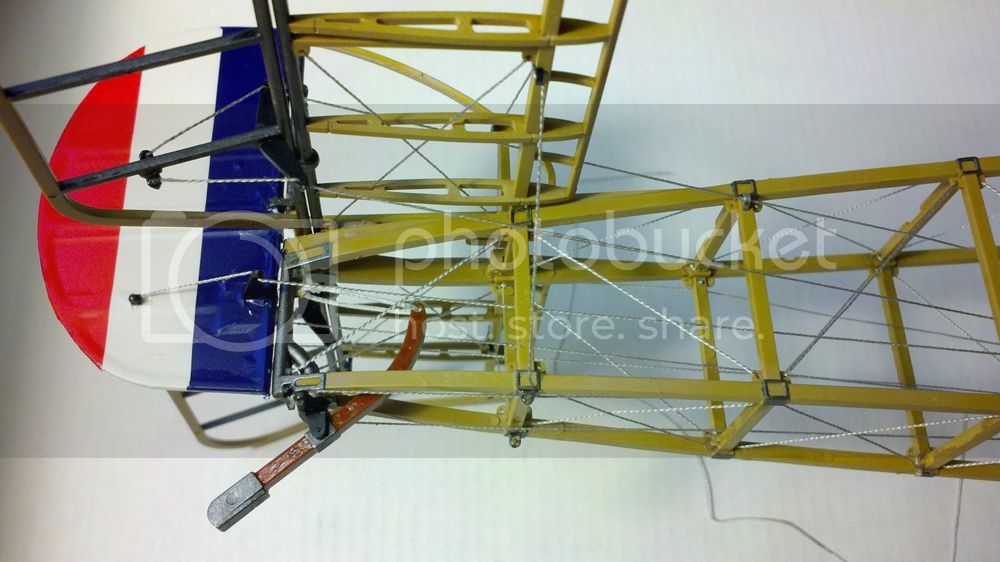
As promised, rigging the tail control surfaces:
First a note of correction from yesterday's post. If you're going to use the solid (with fabric cover) rudder and decal, I suggest NOT waiting until the rudder is installed on to the fin to put the decal on. Do it while the rudder is still separate. It's possible to do it once it's attached, but a lot easier if you put the decals on first.
Right, on to the rigging. First off, make sure everything is dry and the elevators and rudder hinges are solid, still allowing movement. Then start untangling the lines and leading them to their appropriate control horn. Study the instructions carefully here and be ready to turn back to the page that showed how the controls were originally rigged. Take the tape label off one line at a time, lead that line through the fuselage (again, as shown in the instructions) and through any leads (the upper elevator lines go through a lead outside the fuselage, see photo below.) Here's a picture of the completed tail control rigging:
I started with the elevators just because of the decal issue with the rudder. If you've done the rudder correctly, you might want to start here because those lines are inside, but since this is such a large model there's room to work. If you coated the ends of the lines with cyano glue earlier as recommended, it will be a lot easier to get them through the tiny holes, but I still had to ream a couple of them out a bit (VERY carefully, with the tip of a sharp knife blade).
I would lead the line though the control horn and then through the final anchor point, then put a drop of cyano glue on the anchor point to hold everything solid. Especially with the rudder and the tail skid, be sure the controls and the rudder bar are in neutral position when you glue them up, or things won't line up correctly. Work slowly and go along the entire line to be sure it goes from the cockpit through the fuselage and out to the controls correctly before you glue. If it's wrong, it's a lot easier to pull the line out and rethread it before you glue than after! And work one line at a time to not mix anything up (I only mislabeled one line, not bad for me!)
Oh, here's something the instructions don't mention. The elevator controls are one line per side (c1, 2 and d1, 2). Remember a few posts earlier I told you not to glue the line at the base of the joystick and allow it to run free? This makes it easier to line everything up now. BUT, once you've glued those lines in position at the elevator, position the elevator and stick in the neutral position and put a drop of cyano on the line at the base of the joystick now. This way, you'll be able to operate the elevators and the stick will move (and visa versa).
Here's how the cockpit looks with all the lines stretched out and attached to the control surfaces:
MUCH neater than it was (though I still don't know how the pilot kept his feet from getting tangled in there). Yes, I know the rudder bar looks offset. It is a bit, my fault, though it looks better in real life.
Here is how the control surfaces look offset:
And here's how the office looks in that condition:
Frankly, after all that, I can't believe it actually all works! My son, on the other hand, thinks I'm a huge dork. Oh well.
By the way, I was looking things over and noticed that the landing gear does have the elastic thread wrapped around the axles. This is how it's supposed to look, remember they wrapped bungee cord there as shock absorbers. Unfortunately, Hasegawa would have you do this in the very last step after all the rigging is done, just before you add the wheels. I decided to to it now, while the axles were much easier to get at:
Just a simple shortcut to save you some angst later. (NOTE ADDED LATER: Do NOT do this now! I did and found to my regret that I should have waited until the instructions told me to do this, see 1 September post.)
So far so good! Comments welcome, as always.
Michael
First a note of correction from yesterday's post. If you're going to use the solid (with fabric cover) rudder and decal, I suggest NOT waiting until the rudder is installed on to the fin to put the decal on. Do it while the rudder is still separate. It's possible to do it once it's attached, but a lot easier if you put the decals on first.
Right, on to the rigging. First off, make sure everything is dry and the elevators and rudder hinges are solid, still allowing movement. Then start untangling the lines and leading them to their appropriate control horn. Study the instructions carefully here and be ready to turn back to the page that showed how the controls were originally rigged. Take the tape label off one line at a time, lead that line through the fuselage (again, as shown in the instructions) and through any leads (the upper elevator lines go through a lead outside the fuselage, see photo below.) Here's a picture of the completed tail control rigging:

I started with the elevators just because of the decal issue with the rudder. If you've done the rudder correctly, you might want to start here because those lines are inside, but since this is such a large model there's room to work. If you coated the ends of the lines with cyano glue earlier as recommended, it will be a lot easier to get them through the tiny holes, but I still had to ream a couple of them out a bit (VERY carefully, with the tip of a sharp knife blade).
I would lead the line though the control horn and then through the final anchor point, then put a drop of cyano glue on the anchor point to hold everything solid. Especially with the rudder and the tail skid, be sure the controls and the rudder bar are in neutral position when you glue them up, or things won't line up correctly. Work slowly and go along the entire line to be sure it goes from the cockpit through the fuselage and out to the controls correctly before you glue. If it's wrong, it's a lot easier to pull the line out and rethread it before you glue than after! And work one line at a time to not mix anything up (I only mislabeled one line, not bad for me!)
Oh, here's something the instructions don't mention. The elevator controls are one line per side (c1, 2 and d1, 2). Remember a few posts earlier I told you not to glue the line at the base of the joystick and allow it to run free? This makes it easier to line everything up now. BUT, once you've glued those lines in position at the elevator, position the elevator and stick in the neutral position and put a drop of cyano on the line at the base of the joystick now. This way, you'll be able to operate the elevators and the stick will move (and visa versa).
Here's how the cockpit looks with all the lines stretched out and attached to the control surfaces:

MUCH neater than it was (though I still don't know how the pilot kept his feet from getting tangled in there). Yes, I know the rudder bar looks offset. It is a bit, my fault, though it looks better in real life.
Here is how the control surfaces look offset:

And here's how the office looks in that condition:

Frankly, after all that, I can't believe it actually all works! My son, on the other hand, thinks I'm a huge dork. Oh well.
By the way, I was looking things over and noticed that the landing gear does have the elastic thread wrapped around the axles. This is how it's supposed to look, remember they wrapped bungee cord there as shock absorbers. Unfortunately, Hasegawa would have you do this in the very last step after all the rigging is done, just before you add the wheels. I decided to to it now, while the axles were much easier to get at:

Just a simple shortcut to save you some angst later. (NOTE ADDED LATER: Do NOT do this now! I did and found to my regret that I should have waited until the instructions told me to do this, see 1 September post.)
So far so good! Comments welcome, as always.
Michael
captfue
Joined: September 02, 2006
KitMaker: 785 posts
AeroScale: 2 posts
Posted: Monday, August 18, 2014 - 10:40 AM UTC
really cool work....
ludwig113
Joined: February 05, 2008
KitMaker: 1,381 posts
AeroScale: 1,110 posts
Posted: Tuesday, August 19, 2014 - 03:35 AM UTC
very nice
MichaelSatin
Joined: January 19, 2008
KitMaker: 3,909 posts
AeroScale: 2,904 posts
Posted: Sunday, August 24, 2014 - 10:39 AM UTC
Thanks Anthony and Paul!
OK, better sit down everyone, this is going to be a long one.
Now that the tail controls are all rigged, it's time to build the wings. Ah, but I've already done that! Doesn't it feel kinda good to get to a point like this and find that you've already done it? Well, it does to me.
But not so fast there. First off, I haven't added the ailerons and I need to do that. Actually, just follow the instructions and that's pretty easy (just don't forget to cut off those plastic tabs if you want them to move, which I do.) But also, these are the steps where you rig the bracing wires for the wing interiors. It looks pretty straightforward in the instructions, but the devil (as usual) is in the details.
First off, Hasegawa again advises us to coat the end of the pieces of thread in cyano glue to make them stiff. This is a very good idea here as it's much easier to poke the ends through the very small molded in rigging holes this way. Next, careful study of the instructions indicate which holes in the ribs the thread should go through and whether the thread should loop over or under various solid structures. While this might seem to be overkill, it's not. See the picture below of the outer starboard upper wing panel:
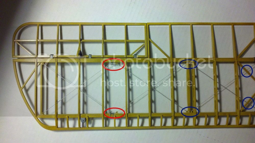
Note that I've circled some parts in red and some in blue. The blue circled bits are places where I followed the instructions but am not sure it was vital. The red circled areas ARE important. This is where the interplane struts will later attach and if the thread is inside these areas instead of outside, it will interfere with the fit of those strut assemblies. Here's the center section of the upper wing:
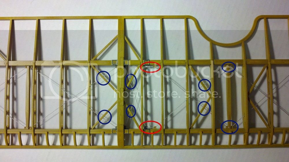
Same deal but this time the red circles indicate where the cabane struts will attach.
Here's the lower wing showing the place where the interplane struts go:
Note that here the thread goes under the slots, again staying out of the way of where the struts will go.
Basically when I rigged the wings, I didn't cut lengths of thread. I just unwound the thread from the card as I fed it through the wings. When I got to the last hole, I put a drop of cyano on that hole, let it set, pulled the thread taut, and put a drop of glue on the first hole. Two pieces of thread per wing. This way I didn't use more thread that I needed.
These holes are small and the instructions are a little hard to read. If you have a magnifying visor, this is a good place to use it (I used my bifocals and had to stop after a while to avoid going crosseyed). Also a decent pair of sharp tweezers to thread the holes and a sharp knife blade to cut the thread are a must.
OK, I've decided to break this one into two posts, so back to the fuselage next.
Michael
OK, better sit down everyone, this is going to be a long one.
Now that the tail controls are all rigged, it's time to build the wings. Ah, but I've already done that! Doesn't it feel kinda good to get to a point like this and find that you've already done it? Well, it does to me.
But not so fast there. First off, I haven't added the ailerons and I need to do that. Actually, just follow the instructions and that's pretty easy (just don't forget to cut off those plastic tabs if you want them to move, which I do.) But also, these are the steps where you rig the bracing wires for the wing interiors. It looks pretty straightforward in the instructions, but the devil (as usual) is in the details.
First off, Hasegawa again advises us to coat the end of the pieces of thread in cyano glue to make them stiff. This is a very good idea here as it's much easier to poke the ends through the very small molded in rigging holes this way. Next, careful study of the instructions indicate which holes in the ribs the thread should go through and whether the thread should loop over or under various solid structures. While this might seem to be overkill, it's not. See the picture below of the outer starboard upper wing panel:

Note that I've circled some parts in red and some in blue. The blue circled bits are places where I followed the instructions but am not sure it was vital. The red circled areas ARE important. This is where the interplane struts will later attach and if the thread is inside these areas instead of outside, it will interfere with the fit of those strut assemblies. Here's the center section of the upper wing:

Same deal but this time the red circles indicate where the cabane struts will attach.
Here's the lower wing showing the place where the interplane struts go:

Note that here the thread goes under the slots, again staying out of the way of where the struts will go.
Basically when I rigged the wings, I didn't cut lengths of thread. I just unwound the thread from the card as I fed it through the wings. When I got to the last hole, I put a drop of cyano on that hole, let it set, pulled the thread taut, and put a drop of glue on the first hole. Two pieces of thread per wing. This way I didn't use more thread that I needed.
These holes are small and the instructions are a little hard to read. If you have a magnifying visor, this is a good place to use it (I used my bifocals and had to stop after a while to avoid going crosseyed). Also a decent pair of sharp tweezers to thread the holes and a sharp knife blade to cut the thread are a must.
OK, I've decided to break this one into two posts, so back to the fuselage next.
Michael
MichaelSatin
Joined: January 19, 2008
KitMaker: 3,909 posts
AeroScale: 2,904 posts
Posted: Sunday, August 24, 2014 - 11:01 AM UTC
OK, back to the cockpit and fuselage. First off some fairly straightforward building of the auxiliary fuel tank and seat. The seat back is supposed to be bent around (it's molded flat) which is actually pretty easy to do. I glued one side of it to the seat bottom, let it dry overnight, then bent it around to fit the curve the next day. Then I installed the parts in the fuselage.
Once again I had to use strips of tape to pull the fuselage sides in so the tank would fit correctly. No big deal, just something to be aware of.
Next it's time to install parts F8 and F9. These are channels that directed the engine exhaust away from the cockpit. Hasegawa include an errata sheet for these as the original instructions show the aileron control cables going through the wrong hole here. The errata sheet show not to glue in the channel pieces as they're supposed to be removable to show detail later. How this would work with all the rigging attaching to them I have no idea, so I glued them on. I'll let you know later if this was a bad idea.
Next build up and install the gun breeches. The installation is a little fiddly, but fairly clear in the instructions and fairly self evident with the actual parts in place:
Not a fun sight for the pilot, having these things right in front of his face!
Next up is the upper and lower bracing wires for the fuselage. These went much like the wings, again being careful to loop the thread inside the fuselage when going around frames as there will be a turtle deck part fitting on top which needs to have clear attachment points.
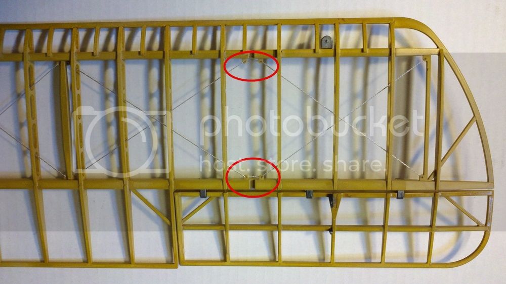
This step also has you rig the bracing wire in the horizontal stabilizer. While this seems simple enough, there is an issue and that's the rigging holes at the very aft end of the fuselage circled in red below:
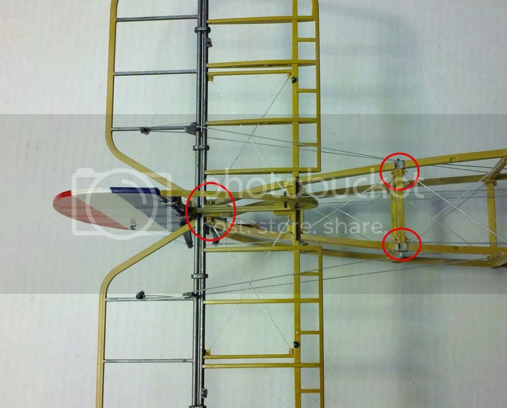
I also circled the frame to show how the thread here loops inside. At the tail, Hasegawa would have you loop the thread under the tail structure, but I found there simply wasn't room. So I simply started my thread at these hole and worked my way out, using two pieces where Hasegawa call for one. All taken care of.
One also rigs the bottom of the fuselage bracing.
The key here, as in the wings (and everywhere else) is to work slowly and check to make sure everything is running straight and not fouling anything else before committing glue. Again, just like the old carpenters' adage: measure twice, cut once.
Whew. My eyes hurt. That'll be all for this weekend. Next week it's the fuselage side bracing and that looks a real treat!
As always, questions and comments welcome!
Michael


Once again I had to use strips of tape to pull the fuselage sides in so the tank would fit correctly. No big deal, just something to be aware of.
Next it's time to install parts F8 and F9. These are channels that directed the engine exhaust away from the cockpit. Hasegawa include an errata sheet for these as the original instructions show the aileron control cables going through the wrong hole here. The errata sheet show not to glue in the channel pieces as they're supposed to be removable to show detail later. How this would work with all the rigging attaching to them I have no idea, so I glued them on. I'll let you know later if this was a bad idea.

Next build up and install the gun breeches. The installation is a little fiddly, but fairly clear in the instructions and fairly self evident with the actual parts in place:

Not a fun sight for the pilot, having these things right in front of his face!
Next up is the upper and lower bracing wires for the fuselage. These went much like the wings, again being careful to loop the thread inside the fuselage when going around frames as there will be a turtle deck part fitting on top which needs to have clear attachment points.

This step also has you rig the bracing wire in the horizontal stabilizer. While this seems simple enough, there is an issue and that's the rigging holes at the very aft end of the fuselage circled in red below:

I also circled the frame to show how the thread here loops inside. At the tail, Hasegawa would have you loop the thread under the tail structure, but I found there simply wasn't room. So I simply started my thread at these hole and worked my way out, using two pieces where Hasegawa call for one. All taken care of.
One also rigs the bottom of the fuselage bracing.

The key here, as in the wings (and everywhere else) is to work slowly and check to make sure everything is running straight and not fouling anything else before committing glue. Again, just like the old carpenters' adage: measure twice, cut once.
Whew. My eyes hurt. That'll be all for this weekend. Next week it's the fuselage side bracing and that looks a real treat!
As always, questions and comments welcome!
Michael

dolly15

Joined: May 20, 2004
KitMaker: 8,227 posts
AeroScale: 3,915 posts

Posted: Tuesday, August 26, 2014 - 08:54 AM UTC
Nice to see something in 1/16th.Lookin' good.Cheers! John. 
wing_nut
Joined: June 02, 2006
KitMaker: 1,212 posts
AeroScale: 468 posts
Posted: Wednesday, August 27, 2014 - 11:50 PM UTC
Impressive work. Looking forward to the end product .
MichaelSatin
Joined: January 19, 2008
KitMaker: 3,909 posts
AeroScale: 2,904 posts
Posted: Saturday, August 30, 2014 - 12:10 PM UTC
Thank you John and Marc!
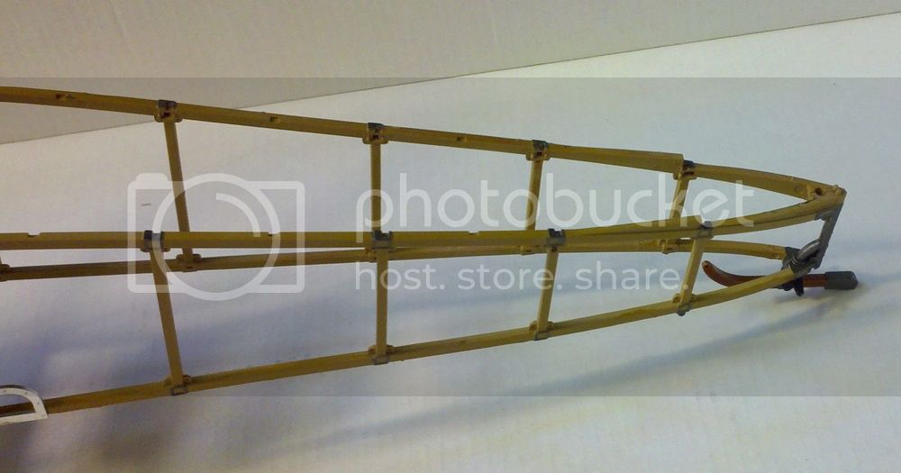
OK, on to the fuselage side bracing. Looking at the instructions, this looks like it's going to be a real bear, but actually diving in and doing it isn't so bad. Again, the way I did this was to not cut off lengths of thread, but to feed it through the provided holes and unwind it off the card as I go, thus allowing me to adjust the length and tautness as I move along.
The keys again here are: remember to use a little super glue to coat the end of the thread to make it stiff and easier to thread through the holes and be VERY careful as you go along to watch where the bracing rigging is going and where the existing control rigging already is so as not to foul anything.
Here's the front end of the first stage of the bracing:
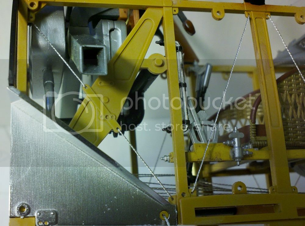
Note how it goes through the two holes in the bracket on the large strut. It's actually easier to do this than it looks, but it's not extremely clear in the instructions. A look at the 1:1 scale rigging diagrams provided clears it up.
Here's the first stage around the cockpit:
Again, loop the thread inside the formers. As always, if the end of the thread is stiff with glue, it's easier than it looks.
How Hasegawa have you do it is one long thread doing both sides of the fuselage. You will probably need to pull more thread off the card as you go, adjusting with a tweezers. It's not hard, just a little painstaking. So here's a view of the other side of the fuselage at the tail. You can see what I mean by being careful not to foul the control wires:
When I have all the bracing done for this stage, I carefully inspect it again to make sure nothing is interfering with anything else, then I put a drop of cyano glue on the starting hole and let it set. Then I tug on the line with tweezers through each cell to make sure the line is taut, staring at the first one (by the cockpit) and working my way around the fuselage to the end. A little dab of glue on the forward hole on the opposite side, let it set and snip it off.
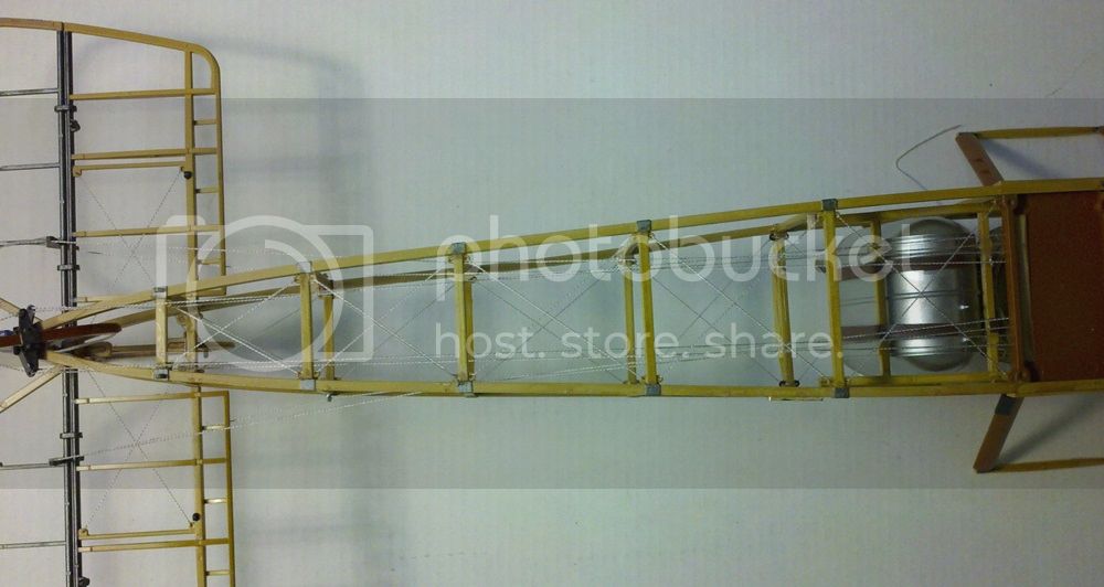
Once the first stage is done, the second stage is actually a bit easier as it's clearer where the thread goes (through the holes not already occupied, that is). Here's an overall view of the completed job:
Here's the forward fuselage finished up:
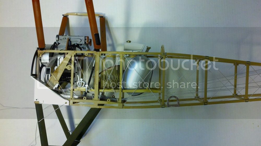
And here's aft:
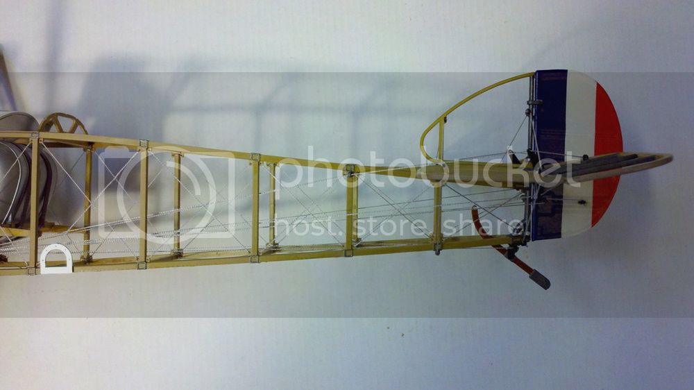
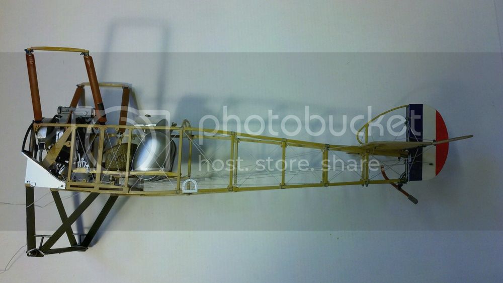
Whew. Crazy as this looks, it's not too terribly bad. Finally this step calls for the final bracing wire at the tail (pretty easy to do after all this, you should be able to see it in the last pic above at the rudder post) and the fuselage rigging is FINISHED.
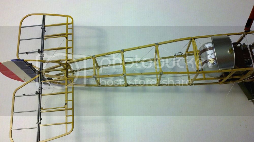
Next stage is putting on the wings and finding out how big this sucker really is. I would recommend gluing the bottom wings on as the last step of your day's work, allowing them to set up solid overnight. They're going to take a lot of handling in your next session, so you want them to be good and strong.
Hi ho everyone! Hopefully more tomorrow!
Michael
OK, on to the fuselage side bracing. Looking at the instructions, this looks like it's going to be a real bear, but actually diving in and doing it isn't so bad. Again, the way I did this was to not cut off lengths of thread, but to feed it through the provided holes and unwind it off the card as I go, thus allowing me to adjust the length and tautness as I move along.
The keys again here are: remember to use a little super glue to coat the end of the thread to make it stiff and easier to thread through the holes and be VERY careful as you go along to watch where the bracing rigging is going and where the existing control rigging already is so as not to foul anything.
Here's the front end of the first stage of the bracing:

Note how it goes through the two holes in the bracket on the large strut. It's actually easier to do this than it looks, but it's not extremely clear in the instructions. A look at the 1:1 scale rigging diagrams provided clears it up.
Here's the first stage around the cockpit:

Again, loop the thread inside the formers. As always, if the end of the thread is stiff with glue, it's easier than it looks.
How Hasegawa have you do it is one long thread doing both sides of the fuselage. You will probably need to pull more thread off the card as you go, adjusting with a tweezers. It's not hard, just a little painstaking. So here's a view of the other side of the fuselage at the tail. You can see what I mean by being careful not to foul the control wires:

When I have all the bracing done for this stage, I carefully inspect it again to make sure nothing is interfering with anything else, then I put a drop of cyano glue on the starting hole and let it set. Then I tug on the line with tweezers through each cell to make sure the line is taut, staring at the first one (by the cockpit) and working my way around the fuselage to the end. A little dab of glue on the forward hole on the opposite side, let it set and snip it off.
Once the first stage is done, the second stage is actually a bit easier as it's clearer where the thread goes (through the holes not already occupied, that is). Here's an overall view of the completed job:

Here's the forward fuselage finished up:

And here's aft:

Whew. Crazy as this looks, it's not too terribly bad. Finally this step calls for the final bracing wire at the tail (pretty easy to do after all this, you should be able to see it in the last pic above at the rudder post) and the fuselage rigging is FINISHED.
Next stage is putting on the wings and finding out how big this sucker really is. I would recommend gluing the bottom wings on as the last step of your day's work, allowing them to set up solid overnight. They're going to take a lot of handling in your next session, so you want them to be good and strong.
Hi ho everyone! Hopefully more tomorrow!
Michael
MichaelSatin
Joined: January 19, 2008
KitMaker: 3,909 posts
AeroScale: 2,904 posts
Posted: Saturday, August 30, 2014 - 12:40 PM UTC
Addendum to the above:
I've found another miss by Hasegawa on this kit. In addition to the lengthwise bracing on the top, bottom, and sides of the fuselage, a close look at my reference (Windsock Datafile 26) shows that the Camel should have diagonal bracing wires crossing between each frame cell as well. This would require a different set of rigging holes than are provided (the holes already there are definitely not big enough for two threads each).
Is this a deal breaker? Not for me. After a while you need to say "enough is enough". If it's an issue for you, I'll bet there's a way to finagle it. But do it before you rig the lengthwise bracing!
Michael
Longshanks8

Joined: July 04, 2013
KitMaker: 430 posts
AeroScale: 18 posts
Posted: Sunday, August 31, 2014 - 12:06 AM UTC
Awesome build, really enjoying it !
Cheers Kev
Cheers Kev
 |

WEB HOSTING BY


Copyright ©2021 AeroScale and Kitmaker Network, a subsidiary of Silver Star Enterprises
All Rights Reserved. Please read our Conditions of Use and Privacy Policy.
All Rights Reserved. Please read our Conditions of Use and Privacy Policy.