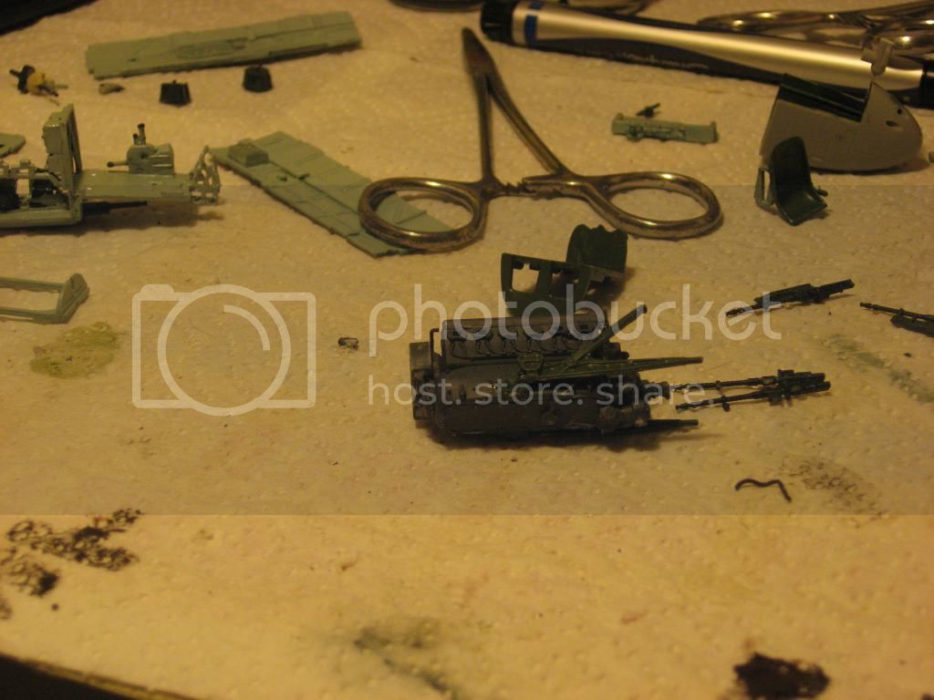
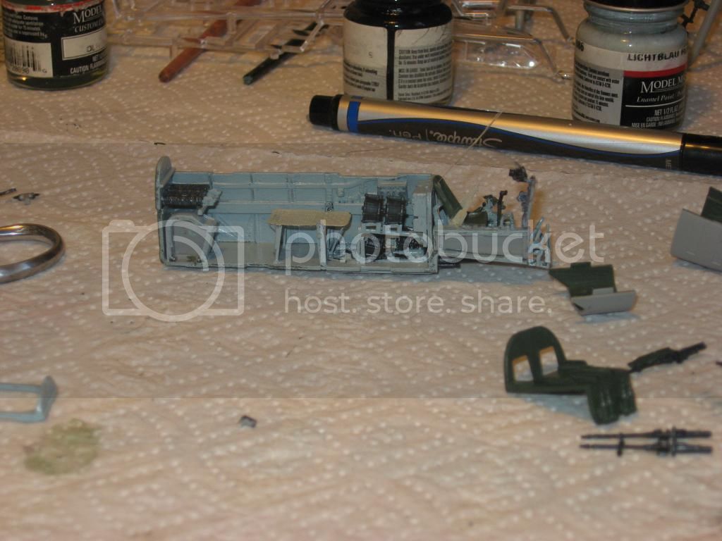
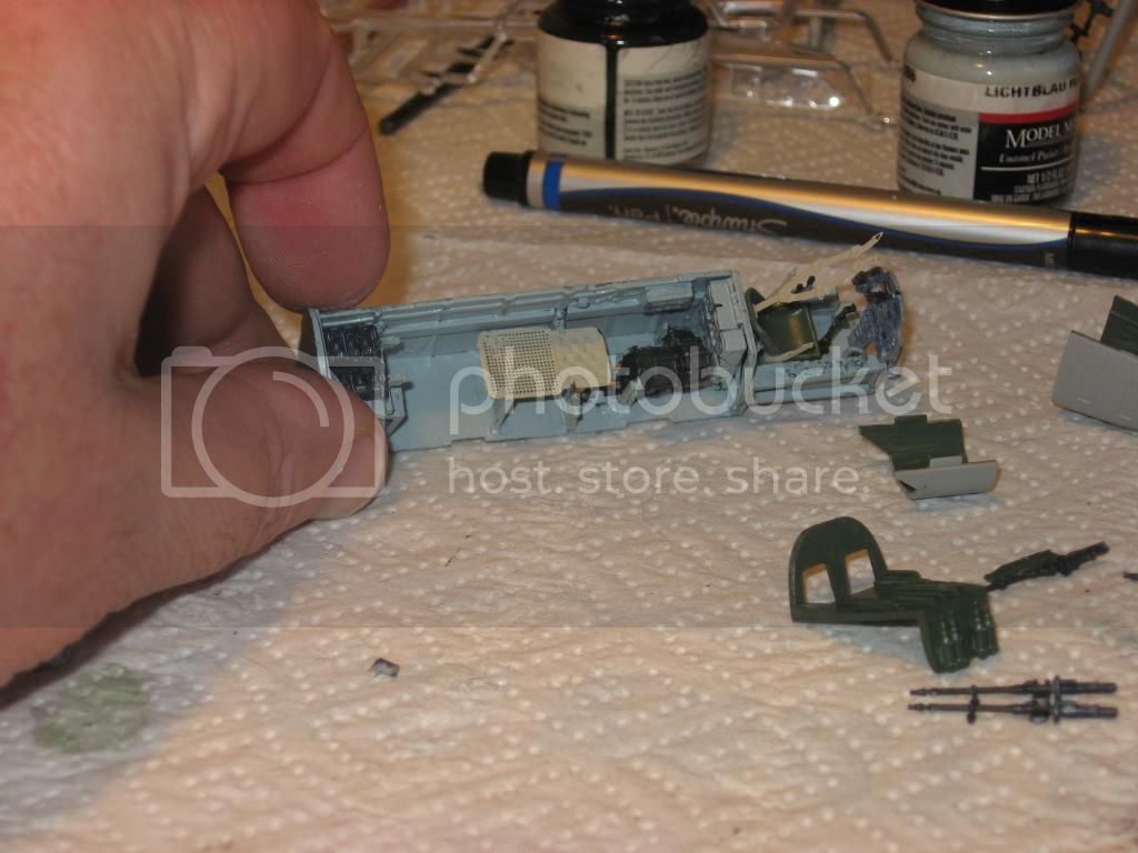
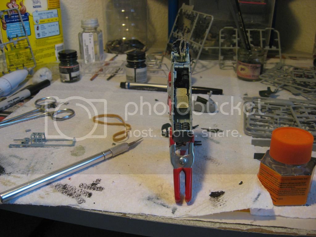
Hi Brian.
I'm following.
Also I'm considering getting the new 1/72nd Airfix bf110 (trop).
So I'm using your build for inspiration.
Cheers
Chris
Hosted by Rowan Baylis
Bf110E-2 Tropical build
chris1

Joined: October 25, 2005
KitMaker: 949 posts
AeroScale: 493 posts

Posted: Thursday, December 11, 2014 - 11:36 AM UTC
BigfootV

Joined: December 24, 2005
KitMaker: 1,624 posts
AeroScale: 385 posts

Posted: Thursday, December 11, 2014 - 12:39 PM UTC
Hello Chris,
Thanks for popping in mate.
If you consider the Dragon kit in future, just remember this build.
Glad to be of service.
See ya in the funnies................

Thanks for popping in mate.
If you consider the Dragon kit in future, just remember this build.

Glad to be of service.
See ya in the funnies................


FlorinM

Joined: August 01, 2011
KitMaker: 385 posts
AeroScale: 173 posts

Posted: Thursday, December 11, 2014 - 04:00 PM UTC
Quoted Text
Hey gang,
Another day and yet WE HAVE A COCKPIT!!!
Took a while.
Assembled one motor last night also. Put more paint on in order to get ready for fuselage/cockpit install.
Which takes me back to this................
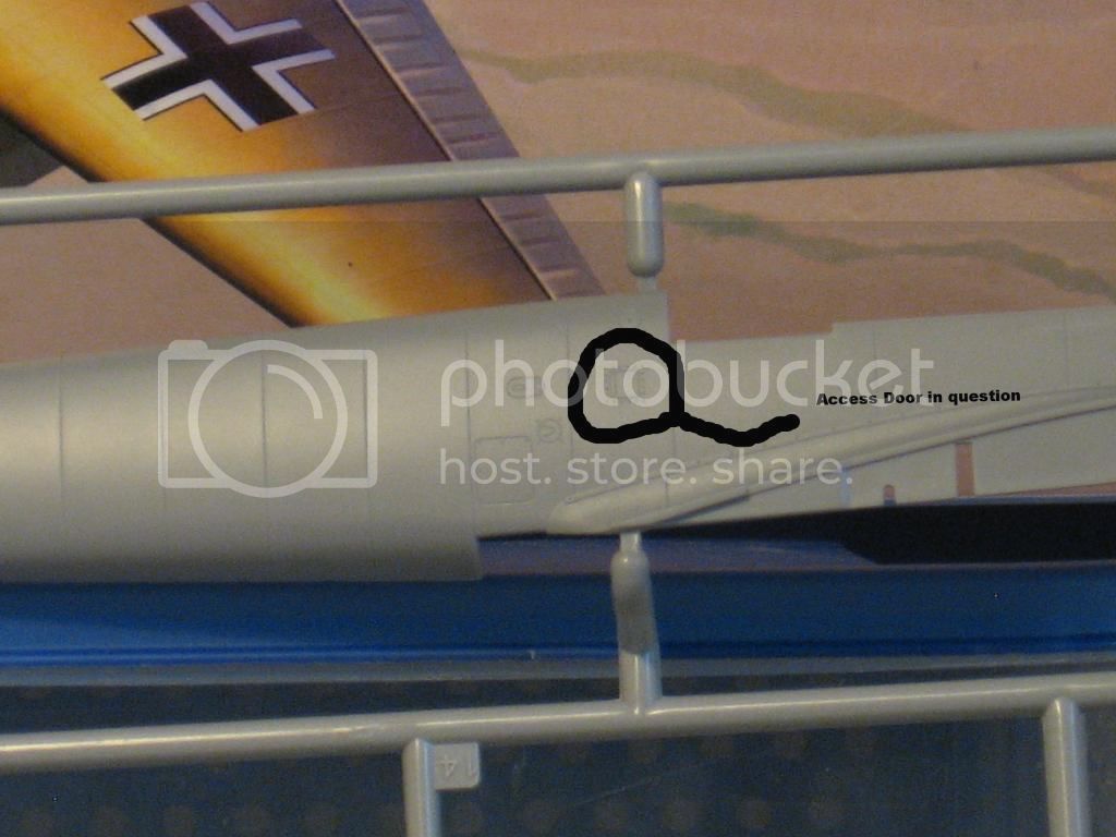
As I stated before the instruction sheet says to cut out and patch this access panel. Based on the photo above should this be done? This may become clearer when I go to put the half's together for the fuselage.
See ya in the funnies.................

That is an air vent flap for the cockpit that is specific to later Bf-110E's, all F's and G's. If you decide to fill it in, you'll have to make another one on the other side, and its top should line up with the access hatch on the frame directly behind it.
BigfootV

Joined: December 24, 2005
KitMaker: 1,624 posts
AeroScale: 385 posts

Posted: Thursday, December 11, 2014 - 10:13 PM UTC
Hello Florin,
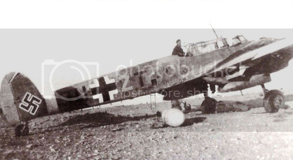
Interesting. O.k., then I'm questioning the production cycle of the E2. When was this omitted in the production run?
Is the Bf110 shown here...........................
an E2 or a later model? If later models had that flap has you have stated, then this is not an E2 shown in the photo above. So why would Dragon have the builder follow those steps to fill it in then turn around and make another one on the opposite side?!?!
Things that make you go Hmmmmmmmmmmm.

Thanks for the input Florin, I think I'm going to leave it alone after the fiasco with the nose last night.

Another question for Dragon, was that trip really necessary?

O.K., enough ranting. Back to the build.
See ya in the funnies...................

Interesting. O.k., then I'm questioning the production cycle of the E2. When was this omitted in the production run?
Is the Bf110 shown here...........................

an E2 or a later model? If later models had that flap has you have stated, then this is not an E2 shown in the photo above. So why would Dragon have the builder follow those steps to fill it in then turn around and make another one on the opposite side?!?!
Things that make you go Hmmmmmmmmmmm.


Thanks for the input Florin, I think I'm going to leave it alone after the fiasco with the nose last night.


Another question for Dragon, was that trip really necessary?


O.K., enough ranting. Back to the build.
See ya in the funnies...................


Arizonakid

Joined: October 03, 2012
KitMaker: 89 posts
AeroScale: 33 posts

Posted: Saturday, December 13, 2014 - 02:16 PM UTC
Hi Brian:
Really nice looking 110
As far as the panel you are refering to. It was not something that was deleted from earlier models. It was something that was added to models later than the one you are building. They were not there on the early models.
And you do not have to cut it out and fill it. Just put some light putty to fill the recessed panel lines and rivets associated with it, and sand smooth to remove it.
HTH. Gary
Really nice looking 110

As far as the panel you are refering to. It was not something that was deleted from earlier models. It was something that was added to models later than the one you are building. They were not there on the early models.
And you do not have to cut it out and fill it. Just put some light putty to fill the recessed panel lines and rivets associated with it, and sand smooth to remove it.
HTH. Gary

BigfootV

Joined: December 24, 2005
KitMaker: 1,624 posts
AeroScale: 385 posts

Posted: Sunday, December 14, 2014 - 04:54 AM UTC
Hello Gary,
Thanks for stopping by.
I'm getting conflicting information from different sources on this hatch/panel/intake. So this is going to be left up to the builder since there is such a large lack of information.
If there is more information out there, I've not found it or have looked in the wrong areas to clear this matter up for future modeler's that would like to build this kit. I have chosen not to mess with it a this time.
Now, I've done some work on the nose today. I had to think about how to go about fixing it before I processed. Here's what I've done.

I took the nose piece and traced around it in black sharpie, fine point, and cut out the trace with small scissors. Plastic sheet styrene thickness is .060.

The black line is were the nose piece cut was ended. This is removed. As seen below.

Piece is glued in place. Outer excess will be sanded to match.


Fuselage half's are in place and glued together.

Next up, wing root, motor install and wings.
See ya in the funnies.............

Thanks for stopping by.
I'm getting conflicting information from different sources on this hatch/panel/intake. So this is going to be left up to the builder since there is such a large lack of information.
If there is more information out there, I've not found it or have looked in the wrong areas to clear this matter up for future modeler's that would like to build this kit. I have chosen not to mess with it a this time.
Now, I've done some work on the nose today. I had to think about how to go about fixing it before I processed. Here's what I've done.

I took the nose piece and traced around it in black sharpie, fine point, and cut out the trace with small scissors. Plastic sheet styrene thickness is .060.

The black line is were the nose piece cut was ended. This is removed. As seen below.

Piece is glued in place. Outer excess will be sanded to match.


Fuselage half's are in place and glued together.

Next up, wing root, motor install and wings.
See ya in the funnies.............


BigfootV

Joined: December 24, 2005
KitMaker: 1,624 posts
AeroScale: 385 posts

Posted: Wednesday, December 17, 2014 - 01:20 AM UTC
Hey gang,
It's update time. Well, the nose repairs are in progress. Time for round 2.
So here's the progress with round 2...........

Repeat Step 1 has done in last post. Trace to fit, cut out with X-acto or scissors.


Notice, No line as in last post. This time the piece is going the line up with the raised tabs that are on Part L1 which mates with Part L12. Attach with glue, let set then remove inside excess CAREFULLY! If you start removing before glue is set you'll pull the piece off and you'll have to start over.
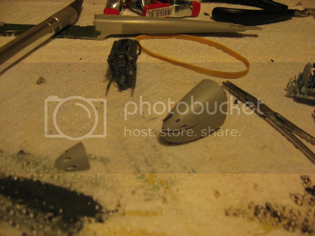
Now, while I'm waiting on that to dry, I've gone ahead and started painting the landing gear housing and doing other prep work for the wing/motor assemblies. While doing this I've run into another part hack that I'll have to do. This one involves Part H11, the lower cowling and engine intake. As shown here..........

Note Parts P1 and P2. This hack is to accommodate these parts. Here is the part in question. (I must apologize for the photo quality....
 )
)

Now this area that is to be removed is not flat like the nose in were you are cutting along some type of line. These areas have rounds to them and well be more of a challenge to remove. So what is more than likely to happen is that I'll have to block off the area before cutting to make sure I don't slip.

Also note that I'm missing a part.........shown above and shown here...........

Which leaves me to ask this, since this part is gone do we have wheels up, try to scratch the part, or have that side collapsed has if it had a gear failure upon landing? Hmmmmm......input on this would be very helpful.
See ya in the funnies......................

It's update time. Well, the nose repairs are in progress. Time for round 2.
So here's the progress with round 2...........

Repeat Step 1 has done in last post. Trace to fit, cut out with X-acto or scissors.


Notice, No line as in last post. This time the piece is going the line up with the raised tabs that are on Part L1 which mates with Part L12. Attach with glue, let set then remove inside excess CAREFULLY! If you start removing before glue is set you'll pull the piece off and you'll have to start over.
Now, while I'm waiting on that to dry, I've gone ahead and started painting the landing gear housing and doing other prep work for the wing/motor assemblies. While doing this I've run into another part hack that I'll have to do. This one involves Part H11, the lower cowling and engine intake. As shown here..........

Note Parts P1 and P2. This hack is to accommodate these parts. Here is the part in question. (I must apologize for the photo quality....

 )
)
Now this area that is to be removed is not flat like the nose in were you are cutting along some type of line. These areas have rounds to them and well be more of a challenge to remove. So what is more than likely to happen is that I'll have to block off the area before cutting to make sure I don't slip.

Also note that I'm missing a part.........shown above and shown here...........

Which leaves me to ask this, since this part is gone do we have wheels up, try to scratch the part, or have that side collapsed has if it had a gear failure upon landing? Hmmmmm......input on this would be very helpful.
See ya in the funnies......................


BigfootV

Joined: December 24, 2005
KitMaker: 1,624 posts
AeroScale: 385 posts

Posted: Thursday, December 18, 2014 - 12:32 PM UTC
Hey Gang,
My apologizes for no updates since Wednesday. I've had to take a small break and let my back rest. Sitting on a 5 gallon bucket doesn't help much either. My hobby chair broke sometime ago and I've not replaced it yet.
So, I'll be at it tomorrow.
See ya in the funnies..............

My apologizes for no updates since Wednesday. I've had to take a small break and let my back rest. Sitting on a 5 gallon bucket doesn't help much either. My hobby chair broke sometime ago and I've not replaced it yet.
So, I'll be at it tomorrow.
See ya in the funnies..............


BigfootV

Joined: December 24, 2005
KitMaker: 1,624 posts
AeroScale: 385 posts

Posted: Friday, December 19, 2014 - 02:58 AM UTC
Hello everybody!
Have I got an update for you. First, the good news. The nose repairs are done. Here's the results.

Removal of excess.

Refit the nose. Not bad if I do say so. Just needs a small amount of putty to fill in, sand and done.


Now we move on to the lower cowling. As I stated this needed to have some work. So here's what happened with that.


Note the notches. Dragon did not mention this in the instructions. This was done to accommodate the oil/air cooler for the engine.


The above is end result. Cut lines are hidden.
Nose guns done. Barrel extender in place.

Lower wing and wheel housing.


Now its at this time we have the bad news. I thought I was losing my mind when I went to install the engines to the fire wall. See if you can spot why in these photos.


Notice anything? I swear Dragon...WTH?!?! The exhaust port on the fire wall is on the wrong side either that or the engines are the same done wrong.

Which lead into this, if the engines exhaust is incorrect, then how will the covers fit? I'll find out soon enough.
See ya in the funnies....................

Have I got an update for you. First, the good news.
 The nose repairs are done. Here's the results.
Removal of excess.

Refit the nose. Not bad if I do say so. Just needs a small amount of putty to fill in, sand and done.


Now we move on to the lower cowling. As I stated this needed to have some work. So here's what happened with that.


Note the notches. Dragon did not mention this in the instructions. This was done to accommodate the oil/air cooler for the engine.


The above is end result. Cut lines are hidden.
Nose guns done. Barrel extender in place.

Lower wing and wheel housing.


Now its at this time we have the bad news. I thought I was losing my mind when I went to install the engines to the fire wall. See if you can spot why in these photos.


Notice anything? I swear Dragon...WTH?!?! The exhaust port on the fire wall is on the wrong side either that or the engines are the same done wrong.


Which lead into this, if the engines exhaust is incorrect, then how will the covers fit? I'll find out soon enough.
See ya in the funnies....................


BigfootV

Joined: December 24, 2005
KitMaker: 1,624 posts
AeroScale: 385 posts

Posted: Saturday, December 20, 2014 - 11:17 PM UTC
Hello everyone,
Remember this...............

Well, its fixed. Photo is blurry but you can make it out.

Spend the rest of the day yesterday working on the nose. Putty, sand, smooth, repeat.

Tail section put together. Awaiting glue to set.

Filled in gap between fuselage and wing root, both sides.


Nose is almost ready, have to shape and blend.

Now I've noticed that the kit has movable wing surfaces both on the leading edge slats and flap areas. This is something that back in the day one had to remove the surface with a saw, sand, fill, rework and reattach to the kit. Dang, I just showed my age.

Anyways, I hope to have more progress done today and this build, I'm hoping, should be done soon.
If I don't post before Christmas, may everyone here have a safe and Happy Christmas.

See ya in the funnies................

Remember this...............

Well, its fixed.
 Photo is blurry but you can make it out.
Spend the rest of the day yesterday working on the nose. Putty, sand, smooth, repeat.


Tail section put together. Awaiting glue to set.

Filled in gap between fuselage and wing root, both sides.


Nose is almost ready, have to shape and blend.

Now I've noticed that the kit has movable wing surfaces both on the leading edge slats and flap areas. This is something that back in the day one had to remove the surface with a saw, sand, fill, rework and reattach to the kit. Dang, I just showed my age.


Anyways, I hope to have more progress done today and this build, I'm hoping, should be done soon.
If I don't post before Christmas, may everyone here have a safe and Happy Christmas.


See ya in the funnies................


BigfootV

Joined: December 24, 2005
KitMaker: 1,624 posts
AeroScale: 385 posts

Posted: Tuesday, December 23, 2014 - 01:51 AM UTC
Hey gang!
Build is coming along however I had to back track and correct something I did, yes we had user error. So, here's the first one........Note the direction of the vertical stabilizer.

Their upside down!!
 This happened because for the majority of the build the instruction are showing under side, upside down views and well I wasn't really paying attention. So chalk on up to user error. Here's the correction.

Now to be honest, I was really upset because this was caught AFTER the glue had set overnight. My thought process blew a fuse and a freak out ensued. So, what to do? Well, since the glue wasn't fully set, I removed the stabilizer by taking the smallest brush I had, dipping it in paint thinner and brushing it into the cracks of the area.
 This causes a chemical reaction with the glue, thus soften it enough to gently remove the part. You may have to lift up with your X-acto to get under the part if it is flush with the other surface.
Second user error, the nose, well, it's a combination of instructions not being clear and user error. Not a good mix. So let's see what happened.

Nose is in place. Note the gap again, not as large as before. Well Dragon would like you do put the nose together in one single piece and attach. Not happening. Why you ask. Remember this........

And this.............

Note the diagram showing you putting on the nose piece as one unit after removing the old nose. Doing this per instruction sheet the guns will not line up with the holes in the new nose piece,A38. In order of this whole area to be flush and gun ports to line up you have to do the following steps:
1. Install gun bay only after fuselage half's are glued.
2. Install Part L1 to bottom of nose guns frame.
3. Install Part L12 to top of L1 as seen in instructions.
4. Finally, carefully, slide A38 over gun barrel extenders and mount flush with the back of Part L12. Note: You may want to leave off gun barrel extenders until A38 is lined up correctly.
Doing these sets one will not have to go though the guessing game on the amount of space needed to be filled in.
Result: See below.


All this leads into what I've done with the engines for the Bf110. The horrror.

Instruction would like you to install engines like this......
Not going to happen.............

Why? Three reasons, first the earlier modification made to one of the engines exhaust(?) pipe being in the wrong area. Second parts B29, B28, B27, B26 lining up with part H11 and H1. Finally, the manifold exhaust ports. Following the instructions will make installing the engine a nightmare.

Note the direction of the exhaust manifold ports, Part D7, D6, D4, D3.
One of these needs to be inside of the engine facing down. Can you tell which one be the way the instructions are......upside down.


Note direction for exhaust manifold port. Facing upward.
Save yourself the stress and follow these instructions.
1. Mount motor on fire wall after motor is completed, part K13(K12) first. Install part D12(D13) on to part B25(B11), lower wing, minus part K14. (Installs later.)
2. Place parts B29, B28, B27, B26 on lower wing part B25(B11). Note the curves have to match with the inside of the wing. If you do this according to instructions and install them together you run the risk of the part not matching up when you go to install engine per instruction. (Note: Parts B29, B28, B27, B26 have tabs on them on the inside of the part, remove them. Makes install easier.)
3. Install engines/fire wall to part K13(K12). Install part K14 and manifold exhaust port. Again watch the direction, inside ports facing down, outside facing up. As seen here.


4. Install part H11, lower cowling. Make sure access tabs line up.
5. Install part H1 upper cowling or you can wait until upper wing parts C7(C4) are in place with lower wing, parts B25(B11). Your choice.
Once you get passed all that we have ANOTHER modification to undertake. And here it is....................

This makes four, for those keeping score.

Anyways, there is light at the end of this build!

That does it for this edition of Triple B, (Bigfoot's Build Blooper.) Sorry, I had to do it. LOL.
See ya in the funnies...............

And Merry Christmas..........

Build is coming along however I had to back track and correct something I did, yes we had user error.
 So, here's the first one........Note the direction of the vertical stabilizer.
Their upside down!!

 This happened because for the majority of the build the instruction are showing under side, upside down views and well I wasn't really paying attention. So chalk on up to user error. Here's the correction.
Now to be honest, I was really upset because this was caught AFTER the glue had set overnight. My thought process blew a fuse and a freak out ensued. So, what to do? Well, since the glue wasn't fully set, I removed the stabilizer by taking the smallest brush I had, dipping it in paint thinner and brushing it into the cracks of the area.

 This causes a chemical reaction with the glue, thus soften it enough to gently remove the part. You may have to lift up with your X-acto to get under the part if it is flush with the other surface.
 Second user error, the nose, well, it's a combination of instructions not being clear and user error. Not a good mix. So let's see what happened.

Nose is in place. Note the gap again, not as large as before. Well Dragon would like you do put the nose together in one single piece and attach. Not happening. Why you ask. Remember this........

And this.............


Note the diagram showing you putting on the nose piece as one unit after removing the old nose. Doing this per instruction sheet the guns will not line up with the holes in the new nose piece,A38. In order of this whole area to be flush and gun ports to line up you have to do the following steps:
1. Install gun bay only after fuselage half's are glued.
2. Install Part L1 to bottom of nose guns frame.
3. Install Part L12 to top of L1 as seen in instructions.
4. Finally, carefully, slide A38 over gun barrel extenders and mount flush with the back of Part L12. Note: You may want to leave off gun barrel extenders until A38 is lined up correctly.
Doing these sets one will not have to go though the guessing game on the amount of space needed to be filled in.
Result: See below.


All this leads into what I've done with the engines for the Bf110. The horrror.


Instruction would like you to install engines like this......
Not going to happen.............

Why? Three reasons, first the earlier modification made to one of the engines exhaust(?) pipe being in the wrong area. Second parts B29, B28, B27, B26 lining up with part H11 and H1. Finally, the manifold exhaust ports. Following the instructions will make installing the engine a nightmare.

Note the direction of the exhaust manifold ports, Part D7, D6, D4, D3.
One of these needs to be inside of the engine facing down. Can you tell which one be the way the instructions are......upside down.


Note direction for exhaust manifold port. Facing upward.
Save yourself the stress and follow these instructions.
1. Mount motor on fire wall after motor is completed, part K13(K12) first. Install part D12(D13) on to part B25(B11), lower wing, minus part K14. (Installs later.)
2. Place parts B29, B28, B27, B26 on lower wing part B25(B11). Note the curves have to match with the inside of the wing. If you do this according to instructions and install them together you run the risk of the part not matching up when you go to install engine per instruction. (Note: Parts B29, B28, B27, B26 have tabs on them on the inside of the part, remove them. Makes install easier.)
3. Install engines/fire wall to part K13(K12). Install part K14 and manifold exhaust port. Again watch the direction, inside ports facing down, outside facing up. As seen here.


4. Install part H11, lower cowling. Make sure access tabs line up.
5. Install part H1 upper cowling or you can wait until upper wing parts C7(C4) are in place with lower wing, parts B25(B11). Your choice.
Once you get passed all that we have ANOTHER modification to undertake. And here it is....................

This makes four, for those keeping score.


Anyways, there is light at the end of this build!


That does it for this edition of Triple B, (Bigfoot's Build Blooper.) Sorry, I had to do it. LOL.
See ya in the funnies...............


And Merry Christmas..........


BigfootV

Joined: December 24, 2005
KitMaker: 1,624 posts
AeroScale: 385 posts

Posted: Tuesday, December 23, 2014 - 10:53 PM UTC
BigfootV

Joined: December 24, 2005
KitMaker: 1,624 posts
AeroScale: 385 posts

Posted: Friday, December 26, 2014 - 02:23 AM UTC
Hello Everyone,
I hope Santa fulled your wish lists and everyone had a Safe and Merry Christmas.
Here's an update for you.
Remember this.............

Well, here's how that went. First, I marked the area in question with a red fine tip marker.


Note the lower wing red markings, this is smaller then the instruction would have you remove. Ignore the instructions, you will remove too much leading edge wing area. Here's the surface removed on the upper wing with lower wing dry fitted.

Note Part C15(C16) glued on to the upper wing and the lower wing dry fitted with the area removed also. Note that part C15(C16)is flush with the area that was removed on the lower wing.


Here is a closer look at the areas to be removed.

Note lower wing area to be removed how small it is compared to the instruction. Also note the sprue mark that was left after removal. You like need to be careful when scoring to remove.


Wing dry fitted to right side. Left wing leading edge modification completed and waiting to dry.


Notice throughout this build I've not put the smaller details like the lower radio antenna array, wing bomb racks, external fuel drop tank and other fragile parts. Reason: I really did feel like have them break off with all the cutting and moving around this build has been through.
 Those are the last things going on after wings get put in.
I hope to have a coat of paint on it over the weekend along with final touch ups before the start of the New Year.
If you have any comment, please post them here.
See ya in the funnies....................


I hope Santa fulled your wish lists and everyone had a Safe and Merry Christmas.
Here's an update for you.
Remember this.............

Well, here's how that went. First, I marked the area in question with a red fine tip marker.


Note the lower wing red markings, this is smaller then the instruction would have you remove. Ignore the instructions, you will remove too much leading edge wing area. Here's the surface removed on the upper wing with lower wing dry fitted.

Note Part C15(C16) glued on to the upper wing and the lower wing dry fitted with the area removed also. Note that part C15(C16)is flush with the area that was removed on the lower wing.


Here is a closer look at the areas to be removed.

Note lower wing area to be removed how small it is compared to the instruction. Also note the sprue mark that was left after removal. You like need to be careful when scoring to remove.


Wing dry fitted to right side. Left wing leading edge modification completed and waiting to dry.


Notice throughout this build I've not put the smaller details like the lower radio antenna array, wing bomb racks, external fuel drop tank and other fragile parts. Reason: I really did feel like have them break off with all the cutting and moving around this build has been through.

 Those are the last things going on after wings get put in.
 I hope to have a coat of paint on it over the weekend along with final touch ups before the start of the New Year.
If you have any comment, please post them here.
See ya in the funnies....................


chris1

Joined: October 25, 2005
KitMaker: 949 posts
AeroScale: 493 posts

Posted: Sunday, December 28, 2014 - 12:17 AM UTC
Hi Brian,
Hope you had a good Christmas.
I admire your perseverance with the errors on the kit.
I suspect had this been me then there is a very good chance that that the kit would flown at hi speed into a wall,then followed by language best not repeated in polite company.
Chris
Hope you had a good Christmas.
I admire your perseverance with the errors on the kit.
I suspect had this been me then there is a very good chance that that the kit would flown at hi speed into a wall,then followed by language best not repeated in polite company.
Chris

BigfootV

Joined: December 24, 2005
KitMaker: 1,624 posts
AeroScale: 385 posts

Posted: Sunday, December 28, 2014 - 05:05 AM UTC
Hello Chris,
Thanks. Christmas was somewhat uneventful this year.
Yes, I have done my fair share of
 with this kit, some has been user error I must admit.
I've done some more work to it, finishing up the small areas and steps I skipped on purpose. (Photos pending) Goal is to have it done before the start of the New Year.
Thanks for stopping by. Hope you have a New Year.

See ya in the funnies..........

Thanks. Christmas was somewhat uneventful this year.
Yes, I have done my fair share of

 with this kit, some has been user error I must admit.
 I've done some more work to it, finishing up the small areas and steps I skipped on purpose. (Photos pending) Goal is to have it done before the start of the New Year.
Thanks for stopping by. Hope you have a New Year.


See ya in the funnies..........


BigfootV

Joined: December 24, 2005
KitMaker: 1,624 posts
AeroScale: 385 posts

Posted: Sunday, December 28, 2014 - 11:19 PM UTC
Hello gang,
Well, 2014 is about over and so is this build.

So here's some progress photo's.
First off, Dragon has given one the option of having the flaps/ailerons/elevators can be posed at either a 90/45 degree angles. This can be done by choosing either Part C9, shown here......

which is angled at the 45 degrees. Or this option.........

which is the 90 degrees option. This is Part C2. Mention this because as I stated earlier in the blog, these were not options back in the day as some of older guys can attest to.

Landing gear in place.


Note, Part K14 is missing from above photo. This was missing from kit and I had mentioned that in earlier post as well.

Dry fit wings.

Hey! Somebody took my paint!
 Compare photo's and you'll get the idea.
 Notice, throughout this build, well since the engines were mounted, I've left off the upper and lower cowlings. Why? Well, since the modification/relocating of the lower exhaust, as seen here....................

the lower cowling as been somewhat of a problem child in making it fit flush with the upper cowling. Well, I won.


Now, I don't know if it was the way I put it in or if the Modeling Gods were with me, but I get it finally to behave.
Nose still needs a bit of loving..........but it closer than it was.

Thanks for dropping by. All comments welcome.
See ya in the funnies....................

Well, 2014 is about over and so is this build.


So here's some progress photo's.
First off, Dragon has given one the option of having the flaps/ailerons/elevators can be posed at either a 90/45 degree angles. This can be done by choosing either Part C9, shown here......

which is angled at the 45 degrees. Or this option.........

which is the 90 degrees option. This is Part C2. Mention this because as I stated earlier in the blog, these were not options back in the day as some of older guys can attest to.


Landing gear in place.


Note, Part K14 is missing from above photo. This was missing from kit and I had mentioned that in earlier post as well.

Dry fit wings.

Hey! Somebody took my paint!

 Compare photo's and you'll get the idea.
 Notice, throughout this build, well since the engines were mounted, I've left off the upper and lower cowlings. Why? Well, since the modification/relocating of the lower exhaust, as seen here....................
the lower cowling as been somewhat of a problem child in making it fit flush with the upper cowling. Well, I won.


Now, I don't know if it was the way I put it in or if the Modeling Gods were with me, but I get it finally to behave.
Nose still needs a bit of loving..........but it closer than it was.

Thanks for dropping by. All comments welcome.
See ya in the funnies....................


BigfootV

Joined: December 24, 2005
KitMaker: 1,624 posts
AeroScale: 385 posts

Posted: Monday, December 29, 2014 - 03:58 AM UTC
BigfootV

Joined: December 24, 2005
KitMaker: 1,624 posts
AeroScale: 385 posts

Posted: Wednesday, December 31, 2014 - 10:06 PM UTC
Happy New Year everyone!
110 is in paint shop. I'm having minor issues with paint, I think the humidity is too dry in the apartment. We've had a cold snap here and heater as been on more then I'd like it too be. The paint is drying too quickly and is not leaving an even coat. I'm hand painting, so coverage needs to be as clean and seamless as possible.
Hope to have this solved and paint completed soon.
See ya in the funnies......................


Posted: Wednesday, December 31, 2014 - 11:27 PM UTC
How many modellers use those little red clips? I use them all the time and they are brilliant! Cheap, just the right size, a gentle pressure. Very handy indeed.
Sorry for the interruption.
Karl.
Sorry for the interruption.
Karl.
BigfootV

Joined: December 24, 2005
KitMaker: 1,624 posts
AeroScale: 385 posts

Posted: Wednesday, December 31, 2014 - 11:54 PM UTC
Hello Karl,
No worries mate. No interruption at all. It can get boring hearing one talk to themselves during these build blogs.


Yes, those are very handy. I found those at a grocery store of all places in their home repair/DYI aisle a few months ago. Not seen them since. I think these ran me around $1.50 for the four of them.
Thanks for dropping in.
See ya in the funnies................

No worries mate. No interruption at all. It can get boring hearing one talk to themselves during these build blogs.


Yes, those are very handy. I found those at a grocery store of all places in their home repair/DYI aisle a few months ago. Not seen them since. I think these ran me around $1.50 for the four of them.
Thanks for dropping in.
See ya in the funnies................


BigfootV

Joined: December 24, 2005
KitMaker: 1,624 posts
AeroScale: 385 posts

Posted: Sunday, January 04, 2015 - 11:35 PM UTC
Hello everyone,
Progress on paint has been slow at best. I've had to start over on the wings. In process of repainting. Fuselage underside paint went on today, looks like I may have to sand some high spots.
Overall, all major construction is completed. Paint and final in progress.
See ya in the funnies.......................


Posted: Monday, January 05, 2015 - 02:24 AM UTC
Hi Brian
Sorry for being such a no show on a truly epic build! I almost hate to say it this late, but I do think you need to add a nose intake - John Vasco's book shows it (as does the box-top painting), but the kit's missed it somehow.
All the best
Rowan
Sorry for being such a no show on a truly epic build! I almost hate to say it this late, but I do think you need to add a nose intake - John Vasco's book shows it (as does the box-top painting), but the kit's missed it somehow.
All the best
Rowan

BigfootV

Joined: December 24, 2005
KitMaker: 1,624 posts
AeroScale: 385 posts

Posted: Monday, January 05, 2015 - 04:27 AM UTC
Hello Rowan,
Thank you very much. Not to worry.
Epic build....well..the nose hasn't been a cake walk and adding the intake at this point would be a bigger pain then its worth.
I didn't take notice until you mentioned it.
However, I may see if there is something in my stash that looks close too it.
Hmmmm, and since I've not painted the nose yet......

Thanks for stopping by.
See ya in the funnies.............

Thank you very much. Not to worry.
Epic build....well..the nose hasn't been a cake walk and adding the intake at this point would be a bigger pain then its worth.
I didn't take notice until you mentioned it.
However, I may see if there is something in my stash that looks close too it.
Hmmmm, and since I've not painted the nose yet......


Thanks for stopping by.
See ya in the funnies.............


JohnVasco

Joined: July 27, 2008
KitMaker: 54 posts
AeroScale: 49 posts

Posted: Wednesday, January 07, 2015 - 04:24 AM UTC
Quoted Text
As far as the panel you are refering to. It was not something that was deleted from earlier models. It was something that was added to models later than the one you are building. They were not there on the early models.
And you do not have to cut it out and fill it. Just put some light putty to fill the recessed panel lines and rivets associated with it, and sand smooth to remove it.
HTH. Gary
THE ABOVE INFORMATION IS WRONG!
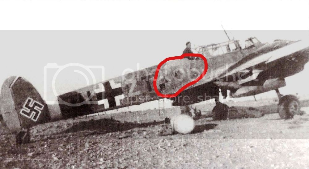
On the 'E' variant, that panel that has been the subject of much debate, was standard. It was an air inlet which drew air in, circulated it around one of the engines, and fed it into the cockpit. The air inlet on the MG cowling between the two central MGs did the same thing and circulated the air around the other engine before feeding it into the cockpit. One fed into the pilot, the other to the Bordfunker. It was the first example on the Bf 110 of cockpit heating for the crew. Here is a clear view of the inlet on a Bf 110 E, S9+GN, of 5./ZG 1. Crewman in the photo is Ofw. Willi Dibowski.

JohnVasco

Joined: July 27, 2008
KitMaker: 54 posts
AeroScale: 49 posts

Posted: Wednesday, January 07, 2015 - 04:34 AM UTC
Quoted Text
Hi Brian
Sorry for being such a no show on a truly epic build! I almost hate to say it this late, but I do think you need to add a nose intake - John Vasco's book shows it (as does the box-top painting), but the kit's missed it somehow.
All the best
Rowan
And picking up on this point by Rowan, here's a pic of the air intake on the nose:

Note also the exhaust deflector plate above the starboard inner exhaust stack. The kit part looks nothing like how it actually was on the aircraft...
 |


