

Eetu,
Simply outstanding workmanship correcting the location of the engine.
I'm just starting on the engine with my 1/32 build, and can only imagine the issues I'm going to be facing. The landing gear is another major issue that will surely test your will.
I'll be building a 1/48 scale version of the F2A-2 sooner then later, and as Brian said, you're build will be our go to reference.
Joel
World War II
Discuss WWII and the era directly before and after the war from 1935-1949.
Discuss WWII and the era directly before and after the war from 1935-1949.
Hosted by Rowan Baylis
1:48 Brewster B-239 (Classic Airframes)
Joel_W

Joined: December 04, 2010
KitMaker: 11,666 posts
AeroScale: 7,410 posts
Posted: Tuesday, July 14, 2015 - 07:16 PM UTC


Emeritus

Joined: March 30, 2004
KitMaker: 2,845 posts
AeroScale: 1,564 posts

Posted: Wednesday, July 15, 2015 - 01:03 AM UTC
Quoted Text
Eetu,
Simply outstanding workmanship correcting the location of the engine.
I'm just starting on the engine with my 1/32 build, and can only imagine the issues I'm going to be facing. The landing gear is another major issue that will surely test your will.
I'll be building a 1/48 scale version of the F2A-2 sooner then later, and as Brian said, you're build will be our go to reference.
Joel
Thanks!

Now I don't, the engine assembly might very well be much less of a chore than on the 1:48 scale kit. I just took a look at the instructions of the 1:32 Special Hobby B-239 (couldn't find those of the F2A-3), and it appears the assembly sequence - assuming it's the same - for the cowling and engine is done much more sensibly than on the 1:48 scale kits. Instead of cramming every engine mounting related component in one long assembly prone to errors (and mistakes, as I've discovered on my 1:48 build), the engine, its closest bulkhead and the foremost mount is built and attached to the cowling assembly.
And they've made different engine mounts for different variants too!

Joel_W
Joined: December 04, 2010
KitMaker: 11,666 posts
AeroScale: 7,410 posts
Posted: Wednesday, July 15, 2015 - 01:20 AM UTC
Quoted Text
Quoted TextEetu,
Simply outstanding workmanship correcting the location of the engine.
I'm just starting on the engine with my 1/32 build, and can only imagine the issues I'm going to be facing. The landing gear is another major issue that will surely test your will.
I'll be building a 1/48 scale version of the F2A-2 sooner then later, and as Brian said, you're build will be our go to reference.
Joel
Thanks!
Now I don't, the engine assembly might very well be much less of a chore than on the 1:48 scale kit. I just took a look at the instructions of the 1:32 Special Hobby B-239 (couldn't find those of the F2A-3), and it appears the assembly sequence - assuming it's the same - for the cowling and engine is done much more sensibly than on the 1:48 scale kits. Instead of cramming every engine mounting related component in one long assembly prone to errors (and mistakes, as I've discovered on my 1:48 build), the engine, its closest bulkhead and the foremost mount is built and attached to the cowling assembly.
And they've made different engine mounts for different variants too!
Eetu,
Hopefully, the engine assembly and fitting will go smoothly for me. I'm still trying to recover from dealing with the landing gear. I measured it today, and to my amazement, the difference in height from one wingtip to the other is just a tad over 1mm.
Joel

magnusf

Joined: May 02, 2006
KitMaker: 1,953 posts
AeroScale: 1,902 posts
Posted: Wednesday, July 15, 2015 - 01:23 PM UTC
Finally a new Eetu-build for my enjoyment! I'm along for the ride !

Magnus
! Magnus
Emeritus
Joined: March 30, 2004
KitMaker: 2,845 posts
AeroScale: 1,564 posts
Posted: Sunday, July 19, 2015 - 06:48 PM UTC
Thanks! Glad to have you aboard as well. 
Update time again. Hopefylly I'll be able to pick up the pace and get this project moving a bit faster now.
After gluing the fuselage landing gear subassembly in the wing bottom, I had to cut off and relocate (twice, actually) the landing gear back wall parts on the upper wing halves, as they didn't line up with the compartment bulkhead. Good thing I made those gear bay back walls from styrene, they were much easier to remove and glue back in than resin glued with CA. So, better glue the fuselage compartment subassembly in place before gluing the parts to the wings.
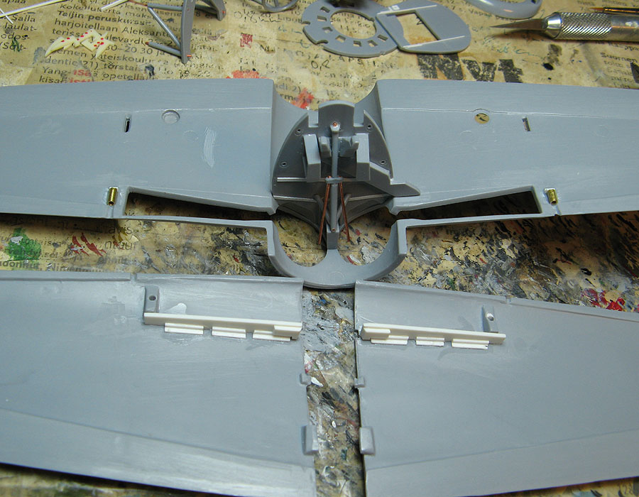
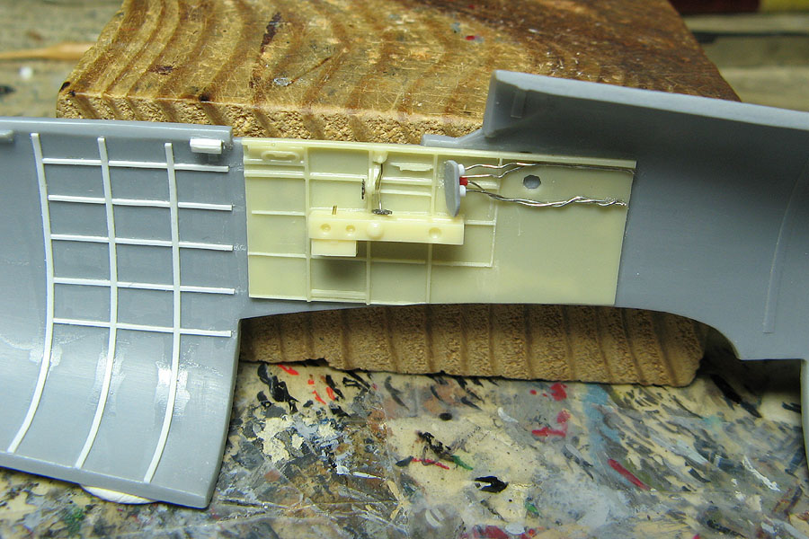
Moving back, I made a bit of a start with the cockpit, so far mainly trying to figure out what parts to use from the CA kit, CMK resin set, and what needs to be scratchbuilt.
Here I've glued in styrene strips to ease and improve gluing the side consoles and rear shelf.

For the reflector gunsight, I'm planning to use the one included in SBS Model's Fokker D.XXI cockpit set. (I plan to build that Fokker as one equipped with a telescopic sight)
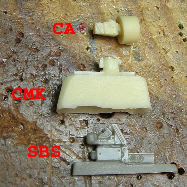
That's by far the best Revi 3 (or Väisälä t.h.m. 40, as license-built in Finland) I've come across. CA's resin part looks like a slightly cut down Revi 16 and CMK's somewhat like a Revi 12 that's missing quite a lot of details... I really hope SBS would make those Revi 3 sights available separately, I got several kits in my stash that could use those.
The instructions in CA's B-239 kit point out wrong PE parts to be used for the instrument panels. Instead of instrument panel PP35 and left side panel PP26, parts PP36 and PP28 should be used (like on CA's F2A-1 instructions).
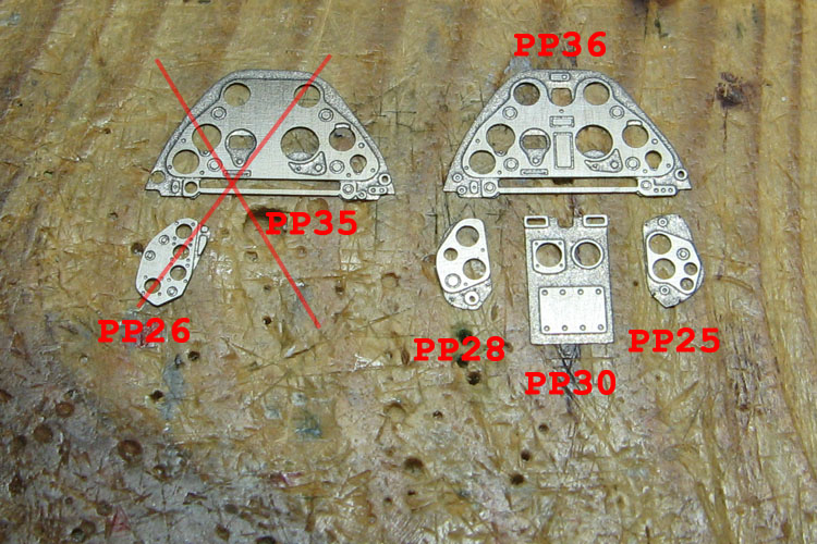
While the side and lower panels don't match my references 100%, I think I can live with those, with perhaps a few additions. The main instrument panel is good. However, due to limitations of PE manufacturing, the panels lack the proper appearance of protective padding, which I think I'll try to do with styrene sheet.
Talking of theose incorrect instrument panels, I have a hunch they originate from Eduard's (whom I believe did the PE for the kit) F2A PE set from 2001. Have a look at the instructions PDF - pretty familiar looking main and left side instrument panels, both labeled as "Finland - late". That is kind of true, in a way, as those appear to represent the instrument panels found in the unlicensed Finnish-build Brewster clone, VL Humu!
So those would be accurate only if you were building a model of HM-671, the sole Humu prototype ever built (which would require some further modifications, btw). Also, for a Humu the main IP is missing two small gauges from the top center, and that Eduard set lacks the Humu-specific lower IP between the rudder pedals...
But back to B-239 stuff.
For the cockpit details, I've been mainly consulting this panoramic 3D sit-in, this Buffalo 1 PDF manual (mainly for names of parts and such though, due to the differences in layout and equipment), a Virtualpilots.fi gallery of BW-372 being restored, as well as two sets on Flickr (-1-, -2-.
Since BW-372 is the sole remaining B-239 around, I'll have to rely on pictures of that.
It seems a combination of both CA kit parts and CMK resin, as well as a careful reading of the instructions and their comparison to references will be needed...

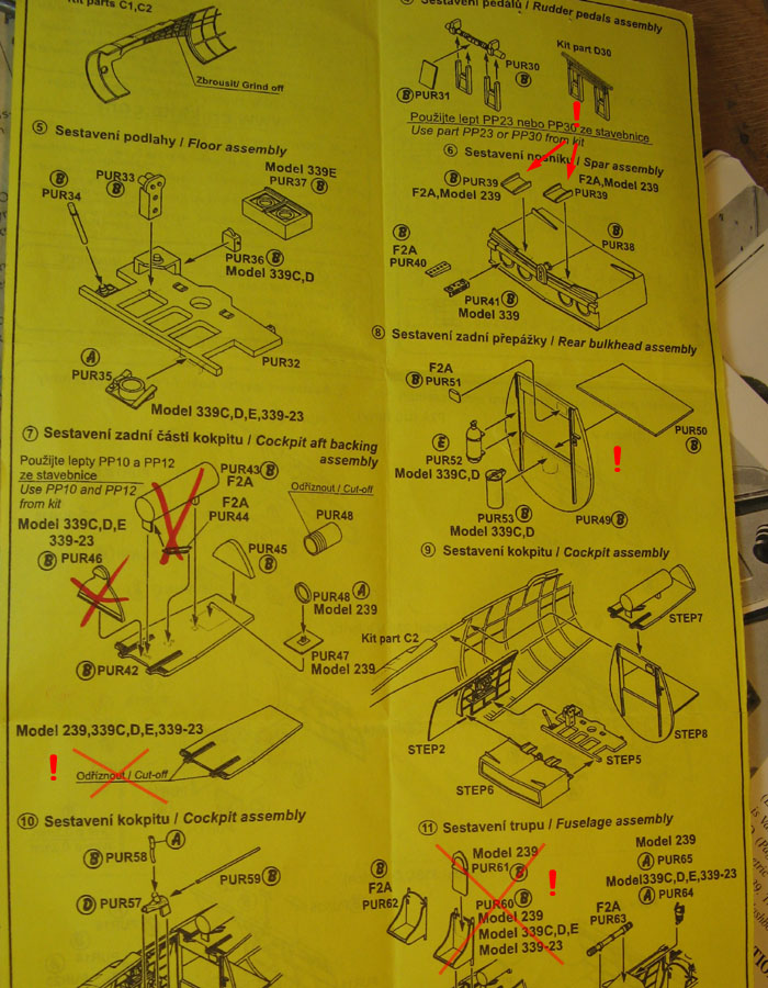
Long story short, with bullet points:
- From CA's instructions: don't use parts D34 and D35, those represent a British compass.
- Make new radio - CA's PE part (PP32) is almost featureless.
- part PUR3 seem to represent radio(?) gear boxes (here seen in pics of F2A-3 cockpit, while PUR4 looks like might represent an empty mount (see pics here. I'll have to scratch-build radio tuning and band selector boxes to replace the resin part.
- Pics of BW-372 show a storage box under the left side console, I'll use the one pointed out for the Dutch version.
- The resin part for the map case (PUR17) looks funny, like it's upside down...
- CMK's instructions fail to mention anything about the PE trim wheels of the CA kit -> use those.
- Foot rests in CMK set are way too short, I'll probably make new ones.
- Bulkhead behind seats needs further modification (compare to photos linked above)
- Don't trim front of rear shelf (PUR42)
- Use F2A seat (PUR62), scratchbuild seat armor.
To close this update, I have a couple of questions.
Would someone know what is the box-like device with a gauge that's attached to the side of the left side console? Here seen in the lower right corner. That can also be seen pretty well in the 3D sit-in linked above. Could it be the oxygen regulator?
The Buffalo mk.1 manual (link above) says there's the oxygen regulator bracket where the radio control box is on the BW-372, so it being in a different location would make sense.
What would have been the likely content of these two brackets above the radio control box?
That's it for this time. Hopefully I'll get this one going properly and the next update will both come sooner and also have more actual progress.
Update time again. Hopefylly I'll be able to pick up the pace and get this project moving a bit faster now.
After gluing the fuselage landing gear subassembly in the wing bottom, I had to cut off and relocate (twice, actually) the landing gear back wall parts on the upper wing halves, as they didn't line up with the compartment bulkhead. Good thing I made those gear bay back walls from styrene, they were much easier to remove and glue back in than resin glued with CA. So, better glue the fuselage compartment subassembly in place before gluing the parts to the wings.
Moving back, I made a bit of a start with the cockpit, so far mainly trying to figure out what parts to use from the CA kit, CMK resin set, and what needs to be scratchbuilt.
Here I've glued in styrene strips to ease and improve gluing the side consoles and rear shelf.
For the reflector gunsight, I'm planning to use the one included in SBS Model's Fokker D.XXI cockpit set. (I plan to build that Fokker as one equipped with a telescopic sight)
That's by far the best Revi 3 (or Väisälä t.h.m. 40, as license-built in Finland) I've come across. CA's resin part looks like a slightly cut down Revi 16 and CMK's somewhat like a Revi 12 that's missing quite a lot of details... I really hope SBS would make those Revi 3 sights available separately, I got several kits in my stash that could use those.
The instructions in CA's B-239 kit point out wrong PE parts to be used for the instrument panels. Instead of instrument panel PP35 and left side panel PP26, parts PP36 and PP28 should be used (like on CA's F2A-1 instructions).
While the side and lower panels don't match my references 100%, I think I can live with those, with perhaps a few additions. The main instrument panel is good. However, due to limitations of PE manufacturing, the panels lack the proper appearance of protective padding, which I think I'll try to do with styrene sheet.
Talking of theose incorrect instrument panels, I have a hunch they originate from Eduard's (whom I believe did the PE for the kit) F2A PE set from 2001. Have a look at the instructions PDF - pretty familiar looking main and left side instrument panels, both labeled as "Finland - late". That is kind of true, in a way, as those appear to represent the instrument panels found in the unlicensed Finnish-build Brewster clone, VL Humu!
So those would be accurate only if you were building a model of HM-671, the sole Humu prototype ever built (which would require some further modifications, btw). Also, for a Humu the main IP is missing two small gauges from the top center, and that Eduard set lacks the Humu-specific lower IP between the rudder pedals...
But back to B-239 stuff.
For the cockpit details, I've been mainly consulting this panoramic 3D sit-in, this Buffalo 1 PDF manual (mainly for names of parts and such though, due to the differences in layout and equipment), a Virtualpilots.fi gallery of BW-372 being restored, as well as two sets on Flickr (-1-, -2-.
Since BW-372 is the sole remaining B-239 around, I'll have to rely on pictures of that.
It seems a combination of both CA kit parts and CMK resin, as well as a careful reading of the instructions and their comparison to references will be needed...
Long story short, with bullet points:
- From CA's instructions: don't use parts D34 and D35, those represent a British compass.
- Make new radio - CA's PE part (PP32) is almost featureless.
- part PUR3 seem to represent radio(?) gear boxes (here seen in pics of F2A-3 cockpit, while PUR4 looks like might represent an empty mount (see pics here. I'll have to scratch-build radio tuning and band selector boxes to replace the resin part.
- Pics of BW-372 show a storage box under the left side console, I'll use the one pointed out for the Dutch version.
- The resin part for the map case (PUR17) looks funny, like it's upside down...
- CMK's instructions fail to mention anything about the PE trim wheels of the CA kit -> use those.
- Foot rests in CMK set are way too short, I'll probably make new ones.
- Bulkhead behind seats needs further modification (compare to photos linked above)
- Don't trim front of rear shelf (PUR42)
- Use F2A seat (PUR62), scratchbuild seat armor.
To close this update, I have a couple of questions.
Would someone know what is the box-like device with a gauge that's attached to the side of the left side console? Here seen in the lower right corner. That can also be seen pretty well in the 3D sit-in linked above. Could it be the oxygen regulator?
The Buffalo mk.1 manual (link above) says there's the oxygen regulator bracket where the radio control box is on the BW-372, so it being in a different location would make sense.
What would have been the likely content of these two brackets above the radio control box?
That's it for this time. Hopefully I'll get this one going properly and the next update will both come sooner and also have more actual progress.
Joel_W
Joined: December 04, 2010
KitMaker: 11,666 posts
AeroScale: 7,410 posts
Posted: Sunday, July 19, 2015 - 07:26 PM UTC
Eetu,
Simply outstanding progress. Your dedication to detail in the cockpit simply puts what I did with my 1/32 scale build to shame. My usual focus is for the finished model to be a display piece, so I concentrate on the exterior issues more then the interior ones. But that's just me.
As for the cockpit, your addition with the ribbing really does add so much more to just the resin sidewalls. My research material really focused on the F2A series, so my IP was much different then what you're using. The larger center consul was for all the export versions, and the smaller side IPs were different as well, which you've already correctly have done.
Looking forward to your next update.
Joel

DaveCox

Joined: January 11, 2003
KitMaker: 4,307 posts
AeroScale: 272 posts

Posted: Sunday, July 19, 2015 - 07:56 PM UTC
Watching this and Joel's 1/32 scale build with interest, as I've just bought Tamiya's Buff & Eduard etched cockpit set. Mine will be finished in the RAF (or is it Aussie?) markings from the kit.
Emeritus
Joined: March 30, 2004
KitMaker: 2,845 posts
AeroScale: 1,564 posts
Posted: Thursday, July 23, 2015 - 08:02 PM UTC
Quoted Text
Watching this and Joel's 1/32 scale build with interest, as I've just bought Tamiya's Buff & Eduard etched cockpit set. Mine will be finished in the RAF (or is it Aussie?) markings from the kit.
Nice! I presume the Tamiya kit will go together much easier than this one. RAF or Aussie markings will be a good choice, as the kit depicts a later variant.
Quoted Text
Eetu,
Simply outstanding progress. Your dedication to detail in the cockpit simply puts what I did with my 1/32 scale build to shame. My usual focus is for the finished model to be a display piece, so I concentrate on the exterior issues more then the interior ones. But that's just me.
As for the cockpit, your addition with the ribbing really does add so much more to just the resin sidewalls. My research material really focused on the F2A series, so my IP was much different then what you're using. The larger center consul was for all the export versions, and the smaller side IPs were different as well, which you've already correctly have done.
Looking forward to your next update.
Joel
Thanks, good to hear you're enjoying my build!
Oh yes, there were definite differences in the cockpit equipment between the different variants. Btw, wasn't there also different lower center panels on different export versions?
When it comes to detailing, I've noticed I have a tendency of getting a bit carried away when there's references around. At least I've managed to keep in sensible levels by putting my efforts in details that actually have a chance of being seen in the finished model.

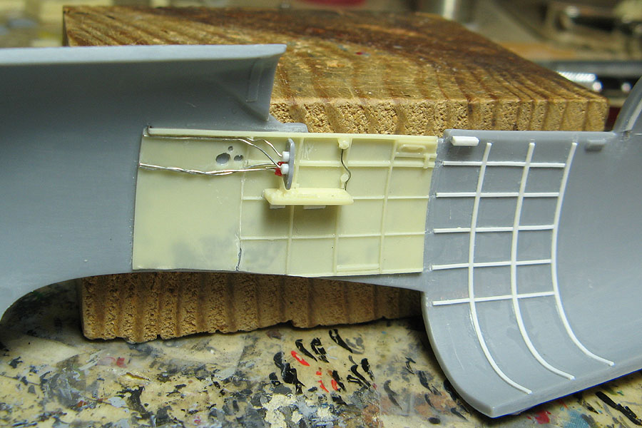
Well, time for another small update, focusing on the cockpit rear shelf this time.
Instead of using the two-part resin shelf of the CMK set (I wonder why they couldn't cast that as a single part?), I figured it would be easier to use the rear wall cut off from the kit part, styrene-to-styrene joints being easier and more forgiving to do.
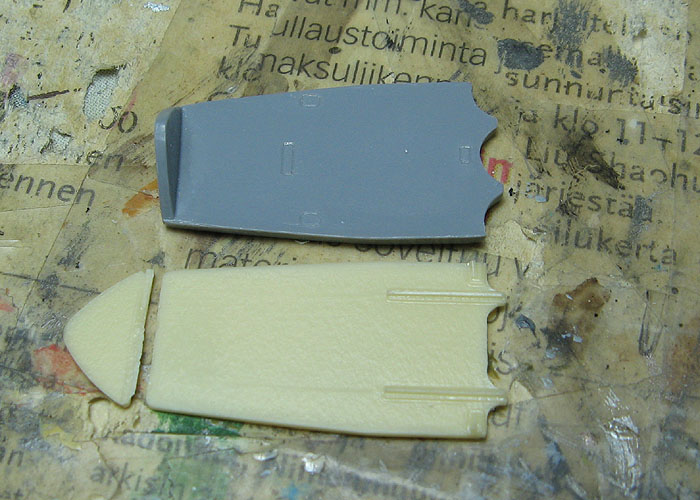
That called for some more styrene strip locators to the fuselage halves.

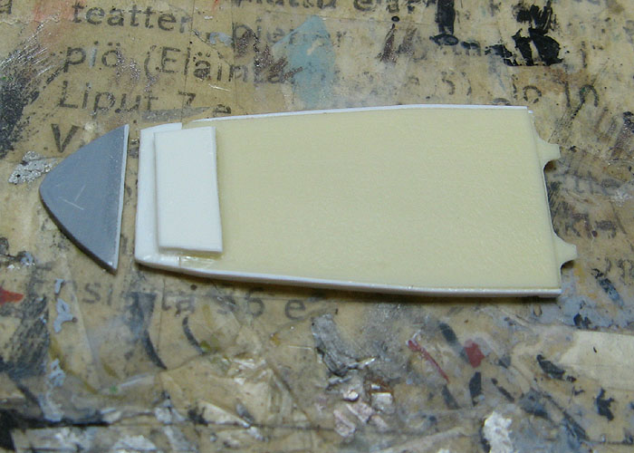
Dry-fitting the cockpit rear bulkhead and rear shelf revealead the latter could use some widening with some styrene strip. The styrene part of the rear shelf also received some to make it taller, something which could have been avoided by cutting the styrene part vertically when separating the rear wall.
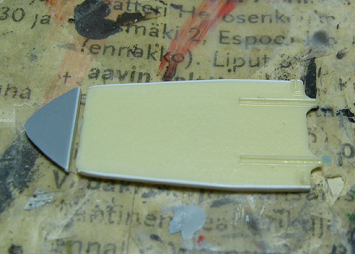
Much better! And as an added bonus, now the joint between the rear shelf and the fuselage is styrene-to-styrene.

That dry-fitting revealed that the resin rear shelf needed a of extension in the rear to avoid a gap when lined up with the cockpit rear bulkhead. I made it longer than needed to allow a sturdy joint to made, with a styrene tab glued under the shelf.
I've been looking throgh my references and I think I got the cockpit equipment figured out pretty well, so I can start with assembly soon.
And talking of that mystery box I suspected of being an oxygen regulator - it's exactly that. The adjustment knob clearly says "oxygen".
Edit: fixed the pictures. I had uploaded uncropped versions by mistake.
Joel_W
Joined: December 04, 2010
KitMaker: 11,666 posts
AeroScale: 7,410 posts
Posted: Thursday, July 23, 2015 - 10:51 PM UTC
Eetu,
Excellent fix for that rear shelf. Looking forward to finally seeing the cockpit completed.
Joel
Excellent fix for that rear shelf. Looking forward to finally seeing the cockpit completed.
Joel
Emeritus
Joined: March 30, 2004
KitMaker: 2,845 posts
AeroScale: 1,564 posts
Posted: Thursday, August 06, 2015 - 05:38 AM UTC
Sorry to disappoint, but I'm not even near finishing the cockpit, but I'm getting there... 
That's the radio selector boxes: strip styrene & brass wire ->

After some surgery, this is approximately how the gunsight (Revi 3 from SBS Model's Fokker D.XXI cockpit set) will fit into the instrument panel. The coaming will need a corresponding notch cut into it, of course.

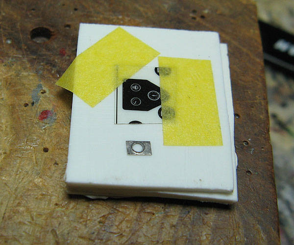
I figured the unused PE & acetate film for the late-variant middle bottom console will make a nice oxygen regulator when combined with a few other parts.
Here's the wings, with the majority of surface detail modified to better match my references: scale drawings by Pentti Manninen and photos of BW-372. Red markings denote removed details, green ones new details scribed in.


I left the panel lines wrapping over the leading edge to be done after assembling the wing in order to avoid trouble lining them up.
The areas pointed by the red ovals were sanded smooth; there was a slightly raised rectangular area on both sides of the wings that didn't seem to belong to the B-239.
The oval inspection hatches (I presume?) on the wings' undersides weren't all 100% correctly shaped or located, but they were close enough so I decided to leave them be, instead of filling up and rescribing every single one. However, the single misplaced oval hatch on the wings' upper surface I did correct. Those were noticably undersized, mislocated, and there should be two on each wing instead of just one.
Also, compared to the scale drawings I'm using, the landing light is not placed exactly correctly, but instead of going through the chore of relocating it, I scribed the panel lines around accordingly - it looks good enough where it is and doesn't stick out.
That's the radio selector boxes: strip styrene & brass wire ->
After some surgery, this is approximately how the gunsight (Revi 3 from SBS Model's Fokker D.XXI cockpit set) will fit into the instrument panel. The coaming will need a corresponding notch cut into it, of course.
I figured the unused PE & acetate film for the late-variant middle bottom console will make a nice oxygen regulator when combined with a few other parts.
Here's the wings, with the majority of surface detail modified to better match my references: scale drawings by Pentti Manninen and photos of BW-372. Red markings denote removed details, green ones new details scribed in.
I left the panel lines wrapping over the leading edge to be done after assembling the wing in order to avoid trouble lining them up.
The areas pointed by the red ovals were sanded smooth; there was a slightly raised rectangular area on both sides of the wings that didn't seem to belong to the B-239.
The oval inspection hatches (I presume?) on the wings' undersides weren't all 100% correctly shaped or located, but they were close enough so I decided to leave them be, instead of filling up and rescribing every single one. However, the single misplaced oval hatch on the wings' upper surface I did correct. Those were noticably undersized, mislocated, and there should be two on each wing instead of just one.
Also, compared to the scale drawings I'm using, the landing light is not placed exactly correctly, but instead of going through the chore of relocating it, I scribed the panel lines around accordingly - it looks good enough where it is and doesn't stick out.
Joel_W
Joined: December 04, 2010
KitMaker: 11,666 posts
AeroScale: 7,410 posts
Posted: Thursday, August 06, 2015 - 11:36 PM UTC
Eetu,
Your cockpit detailing is really looking spectacular. I'm really impressed with all the corrections you've made to the wings.
Joel
Your cockpit detailing is really looking spectacular. I'm really impressed with all the corrections you've made to the wings.
Joel
 |

WEB HOSTING BY


Copyright ©2021 AeroScale and Kitmaker Network, a subsidiary of Silver Star Enterprises
All Rights Reserved. Please read our Conditions of Use and Privacy Policy.
All Rights Reserved. Please read our Conditions of Use and Privacy Policy.