_GOTOBOTTOM
World War II
Discuss WWII and the era directly before and after the war from 1935-1949.
Hosted by Rowan Baylis
1:48 Brewster B-239 (Classic Airframes)
Emeritus
_VISITCOMMUNITY
Uusimaa, Finland
Joined: March 30, 2004
KitMaker: 2,845 posts
AeroScale: 1,564 posts
Posted: Wednesday, June 03, 2015 - 04:18 AM UTC
Having been following Joel_W's build thread for his 1:32 scale Brewster F2A-3, I thought about was time I got started on one of the two 1:48 Classic Airframes kits in my stash.

I'm currently in the very first stages of the build, so this first post will be a quick overview of what I'm working with, before I get some progress documented.


The kit plus the aftermarket (so far...): CMK cockpit and engine sets, Squadron vacuform canopy, and Eduard canopy masks.

Talking of the CMK sets, I feel I just have to go into a bit of a rant about accurate product naming.

With the cockpit set, the packaging doesn't say as much as it should, although I understand it's probably due to the fact that you couldn't have fitted everything in there. Only after opening the package and unfolding the instructions do you see that the set also covers the B-239. However, it seems the instructions should probably be taken with a grain of salt when building a Finnish Brewster, but more of that later when I get to the actual build.


And then we have the engine set. Of course, I should have done some research beforehand to see what it's all about, but I still think it could have been named a lot better and more truthfully. I'm glad I got this at 50% discount for 14€ from online store. Had I paid the full price, I would have probably contacted the store and asked to return it.

It says F2A-1/2/3, detail and casting is very nice, and it includes the front fuselage and associated parts to display the engine with an open cowling. The only catch is the fuselage and cowling parts are for an F2A-2 or -3, leaving the majority of the set unusable for an F2A-1 or B-239.

Well, you can always use just the engine, right? Yeah, probably, if you don't care about having a right type of Cyclone.

To me, it looks like CMK went for the same (or similar) type of engine as the one supplied in the kit, which is different from those on Finnish Brewsters. It can very well be correct for other Brewster variants though.

Oh well, gotta swap that for a Vector R-1820.

Now this is still somewhat different than the Cyclones seen on wartime photos of B-239, their engines having flatter reduction gear housings, but I think I'll say this close enough and settle for it. There's enough challenges ahead to get stuck on things like this.

Next time: hopefully less rants and more actually progress.

chris1
_VISITCOMMUNITY
Auckland, New Zealand
Joined: October 25, 2005
KitMaker: 949 posts
AeroScale: 493 posts
Posted: Wednesday, June 03, 2015 - 04:31 AM UTC
Eetu,
I'm following.
Will be interested to see how things compare with Joels'build.
Now all we need is someone to take on the Tamiya buffalo.

Chris
warmonger
_VISITCOMMUNITY
Oklahoma, United States
Joined: November 08, 2006
KitMaker: 217 posts
AeroScale: 82 posts
Posted: Wednesday, June 03, 2015 - 06:26 AM UTC
I'll be watching your build. I just purchased the Special Hobbies 1/32 Finnish Buffalo from down under (I couldn't find one in the states). Haven't started it yeat, but I am getting the itch.
Redhand
#522
_VISITCOMMUNITY
New Jersey, United States
Joined: January 20, 2013
KitMaker: 1,460 posts
AeroScale: 1,443 posts
Posted: Wednesday, June 03, 2015 - 09:37 AM UTC
I'm watching too. Love the airplane. What variant of the R-1820 did the Finnish A/C use? Would be interested in looking it up. Many years ago I converted a Tamiya F2A-2 kit to a Finnish B-239 using an ancient Aeromaster resin conversion set. Absolutely nothing to write home about, but at least I have one on the shelf. One day I hope to add another, so your build will be interesting to follow in a "So this is how it's done" kind of way.

Plus, as I said, I love the airplane.
heavyjagdpanzer
_VISITCOMMUNITY
Georgia, United States
Joined: February 17, 2013
KitMaker: 173 posts
AeroScale: 108 posts
Posted: Wednesday, June 03, 2015 - 05:44 PM UTC
I have the same kit, I will be watching this build. I really like WW-II Finish aircraft.
jimmaas
Joined: January 11, 2007
KitMaker: 6 posts
AeroScale: 5 posts
Posted: Wednesday, June 03, 2015 - 07:22 PM UTC
Brian ONeill asked "What variant of the R-1820 did the Finnish A/C use? Would be interested in looking it up."

Here are the Wright Aircraft Corp. engines used by different variants of the Buffalo, per Brewster spec sheets:

F2A-1: WAC 1820-34
239: WAC 1820-G5
F2A-2: WAC 1820-40
339B: WAC 1820-G105
339C: WAC 1820-G105
339D: WAC 1820-G205
339E: WAC 1820-G105
F2A-3: WAC 1820-40
339-23: WAC 1820-G5E
Joel_W
Staff MemberAssociate Editor
AUTOMODELER
_VISITCOMMUNITY
New York, United States
Joined: December 04, 2010
KitMaker: 11,666 posts
AeroScale: 7,410 posts
Posted: Wednesday, June 03, 2015 - 08:55 PM UTC
Eetu,
Congratulations on starting your build. I'll be following along with great interest for sure, as I've got a deep, dark fascination with that Chubby little beast of a plane.

As Jim Maas posted the correct Cyclone engine for your build. I'm sure that you already know that the Finnish version Model 239 is basically the export version of the Naval F2A-1.The tail was changed to remove the arresting hook. the gun sight changed to a ring and bead sight, a simplified RDF antenna, and a armament change.

That Vector engine really looks quite nice. I do hate when the conversion sets are for multiple versions, and you end up with more wrong then right parts.

Looking forward to your 1st update.

Joel
Emeritus
_VISITCOMMUNITY
Uusimaa, Finland
Joined: March 30, 2004
KitMaker: 2,845 posts
AeroScale: 1,564 posts
Posted: Saturday, June 06, 2015 - 06:42 AM UTC
Nice to see such interest in my build!


Quoted Text

As Jim Maas posted the correct Cyclone engine for your build. I'm sure that you already know that the Finnish version Model 239 is basically the export version of the Naval F2A-1.The tail was changed to remove the arresting hook. the gun sight changed to a ring and bead sight, a simplified RDF antenna, and a armament change.

That Vector engine really looks quite nice. I do hate when the conversion sets are for multiple versions, and you end up with more wrong then right parts.


Yup, I think I got the basics pretty good. Jim also kindly sent me a document of pointers regarding the kit, which will surely be of help.
Finnish Brewsters were originally equipped with either ring and beads sights or Aldis telescopic sights. In December 1940 they were ordered to be changed to license-built Revi 3C/D reflector sights.
Oh yes, the Vector engine looks gorgeous. I hope I can do it justice.


Well, I think it's time for the first update! Nothing major yet, basically cleaning parts and getting it started.
Gotta start by getting your references together, though.


As per the instructions, I started with the wheel wells and fuselage compartment. Apart from slight depressions on one side of one bulkhead, none of the parts here have any kind of pins or locators, unless one counts scribed marks for placing the struts. Since it looked quite daunting a task to get them aligned properly, I got an idea...


The upper struts of the engine mount don't seem to want to fit over the scribed circular marks for them. Since this will all be inside the fuselage, I think I'll prioritize getting the engine mount sitting properly and just glue the upper struts where they land naturally.


Looking at my references, in those relatively few picture that show the wing gear bays, I couldn't see such heavy ribbing as depicted in the kit's resin parts. As the bay rear wall parts are so simple, I used the resin parts as templates for making styrene versions. Detailing will naturally follow.


While I was at it, I made a start on the wing. No starboard landing light, so that was plugged with the clear part and smoothed over. Halfway between the gear well and the trailing edge - near where an MG compartment hatch is supposed to be located - there was a slightly raised rectangular panel on both sides, which according to my references wasn't present on B-239. Some scraping and sanding took care of those. I'll scribe in the missing hatches later.


I have a feeling both the heavily ribbed wing gear bays and the raised hatches/panels might have been based on the Buffalo mk.I... In Squadron's F2A In Action book, there is a photo of a Buffalo mk.I's underside, with both of those feature clearly visible.

To end this first update, here's the start I've made on the cockpit: cleaned up some of the bigger resin parts and removed the moulded-on sidewall details in the fuselage halves.

Oh, cleaning up that cockpit floor/sidewall piece was fun... The part itself is very thin and fragile, so you can't hold on to anything but the casting plug while sawing it off. And when you finally get the plug removed, cleaning up the part required even more careful handling.


Good night, here's some Nightwish.
chukw1
_VISITCOMMUNITY
California, United States
Joined: November 28, 2007
KitMaker: 817 posts
AeroScale: 729 posts
Posted: Saturday, June 06, 2015 - 06:49 AM UTC
Sweet! I have a couple of these in the stash- the Finnish version's up first! I'll be taking notes, my friend- cheers!
Redhand
#522
_VISITCOMMUNITY
New Jersey, United States
Joined: January 20, 2013
KitMaker: 1,460 posts
AeroScale: 1,443 posts
Posted: Saturday, June 06, 2015 - 08:18 PM UTC
This is definitely going to be a learning experience. Love the idea of pinning the parts.
Redhand
#522
_VISITCOMMUNITY
New Jersey, United States
Joined: January 20, 2013
KitMaker: 1,460 posts
AeroScale: 1,443 posts
Posted: Saturday, June 06, 2015 - 08:30 PM UTC
Not sure how much it adds to your engine references, but here is a photo of the R-1820-34 fitted to a Grumman F2F:


The flat ignition harness ring behind the valve pushrods in the front is certainly a distinctive aspect of these engine models.
Joel_W
Staff MemberAssociate Editor
AUTOMODELER
_VISITCOMMUNITY
New York, United States
Joined: December 04, 2010
KitMaker: 11,666 posts
AeroScale: 7,410 posts
Posted: Saturday, June 06, 2015 - 09:16 PM UTC
Eetu,
An excellent start to a most challenging build. Believe me I know the pain of no pins for joining parts, as the Czech 1/32 build on currently working on doesn't have many either.

The resin cockpit looks excellent, and should add quite a lot to your build.

Brian, Nice pic of the engine. About the only difference I can see is that the push rods should be gloss black. I'm currently working on the ignition wiring, and the harness ring is indeed half flat. Too bad one sees so little of the engine once the cowl is in place.

Joel
Emeritus
_VISITCOMMUNITY
Uusimaa, Finland
Joined: March 30, 2004
KitMaker: 2,845 posts
AeroScale: 1,564 posts
Posted: Sunday, June 07, 2015 - 08:30 PM UTC

Quoted Text

Not sure how much it adds to your engine references, but here is a photo of the R-1820-34 fitted to a Grumman F2F:

The flat ignition harness ring behind the valve pushrods in the front is certainly a distinctive aspect of these engine models.


Yeah, the location of the ignition harness is clearly shown in my references. Thanks for the picture, though. But what's new to me is the half flat shape of the ignition harness ring. I was a bit surprised to see it like that in the Vector engine set, but apparently it's just like it's supposed to be.
Redhand
#522
_VISITCOMMUNITY
New Jersey, United States
Joined: January 20, 2013
KitMaker: 1,460 posts
AeroScale: 1,443 posts
Posted: Sunday, June 07, 2015 - 09:16 PM UTC

Quoted Text

what's new to me is the half flat shape of the ignition harness ring. I was a bit surprised to see it like that in the Vector engine set, but apparently it's just like it's supposed to be.


Yes! It is a strange feature, but typical of radials of this period. I have seen it on other period A/C and engines.
Emeritus
_VISITCOMMUNITY
Uusimaa, Finland
Joined: March 30, 2004
KitMaker: 2,845 posts
AeroScale: 1,564 posts
Posted: Thursday, June 11, 2015 - 02:33 AM UTC
Time for update no. 2. Still nothing that major progress, but some dabbling with the interior parts.

Note to self (and others as well): decide if you are going to do detailing before gluing in detail parts. I thought the fuselage compartment is after all somewhat visible and could benefit from some additional detailing. I think I'll still have to add some more rivets.

Note that in the real thing they're all raised rivets; I settled for recessed detail for the sake of convenience. Also, note that I goofed with the placement of the small V-strut (connecting to the J-shaped part): it should be be almost perpendicular to the bulkhead (perhaps w/ a slight downward angle) instead of the angle I glued it in.

Now the rest of this update is basically all observations on things waiting ahead.

There's an interesting discrepancy between the width of the resin cockpit parts. Comparing the block (fuel tank?) and the frame that goes under the seat, I wonder if it's that way on purpose, or could it be due to shrinkage? Anyway, reportedly the plastic part needs narrowing in order to avoid messing up the dihedral of the wings, but the resin part looks like it needs some styrene sheet glued on both sides in order for it to make proper contact with the cockpit sides.


Interesting surprises continued with the bulkhead that goes right behind the seat. I don't know if it's just because of the way I removed the moulded-in details from the fuselage halves, and/or if I didn't remove enough material, but the sides of the bulkhead fit perfectly both to the fuselage contours and with the resin sidewalls on each sides, while putting a pretty massive downward angle to the bulkhead. I tried to figure out what was wrong, but soon resorted to the easier route of simply modifying the kit part, which fits very well.


While cleaning resin the rudder pedal mount top bar, I managed to break it. That's a little bit too tight a space to drill holes for pins, so I think I'll just use the kit part. Interestingly, the CMK cockpit set includes only the top bar and no pedals at all, the plastic rudder pedals are to be cut off from their mount and glued to the resin part.


Now this is only an initial dryfit, but looks like something needs to be done in order to get the rudder pedals fitting to their mounts...


Joel_W
Staff MemberAssociate Editor
AUTOMODELER
_VISITCOMMUNITY
New York, United States
Joined: December 04, 2010
KitMaker: 11,666 posts
AeroScale: 7,410 posts
Posted: Thursday, June 11, 2015 - 03:10 AM UTC
Eetu,
Looks like I'm not the only one struggling with that chubby little fighter Different kit, different scale, but still issues.

I concur with your decision to go with the better fitting kit parts that you're detailing. The gas tank really isn't very visible once you glue up the fuselage halves unless someone looks directly into the cockpit. Your extra detailing in the wheel well/gun bay adds just enough to fool one's eye.

I'm surprised that the kit rudder peddles are that sort. The resin one doesn't look long enough either.

Still, you're making progress, and that's what counts. Looking forward to your next update.

Joel


Emeritus
_VISITCOMMUNITY
Uusimaa, Finland
Joined: March 30, 2004
KitMaker: 2,845 posts
AeroScale: 1,564 posts
Posted: Friday, June 12, 2015 - 12:48 AM UTC
Well, it's a short-run kit so I pretty well aware what I was getting into.
In addition to always dry fitting everything multiple, another rule of thumb I've taken a habit of keeping in mind when working with short-run kits is never to assume anything. It's better to just dive in with an open mind and see what the kit you're building has in store.
Joel_W
Staff MemberAssociate Editor
AUTOMODELER
_VISITCOMMUNITY
New York, United States
Joined: December 04, 2010
KitMaker: 11,666 posts
AeroScale: 7,410 posts
Posted: Friday, June 12, 2015 - 01:06 AM UTC

Quoted Text

Well, it's a short-run kit so I pretty well aware what I was getting into.
In addition to always dry fitting everything multiple, another rule of thumb I've taken a habit of keeping in mind when working with short-run kits is never to assume anything. It's better to just dive in with an open mind and see what the kit you're building has in store.


Eetu,
That's how I'm doing it once I get into the kit. Being my 1st multi media limited run kit, I was going on assumptions and reviews.
Joel
Emeritus
_VISITCOMMUNITY
Uusimaa, Finland
Joined: March 30, 2004
KitMaker: 2,845 posts
AeroScale: 1,564 posts
Posted: Friday, June 12, 2015 - 02:18 AM UTC
Build reviews and reports are indeed a very valuable resource when building trickier like these.
Oh, I now realized I could have put it a bit clearer. With assumptions I meant mainly the kind that's related to parts fit. That even though the parts of a given kit are (hopefully) designed to fit together and the instructions show how to assemble them, they might not always work that way in real life.
Emeritus
_VISITCOMMUNITY
Uusimaa, Finland
Joined: March 30, 2004
KitMaker: 2,845 posts
AeroScale: 1,564 posts
Posted: Monday, June 22, 2015 - 08:10 PM UTC
Hmm, has at been almost two weeks since my last update? Let's fix that.

Moving away from the fuselage-related things, I built Vector resin engine. Well, most of it anyway; there's still the exhaust pipes, ignition wires (which I'll probably add after painting), and some other parts to add.

Looking at reference photos, it was apparent the reduction gear housing represented a different version than the one used on the B-239, being too long. While far from a perfect solution, I figured it could be made better by cutting away the vertical portion of the housing and reattaching the front portion.


Here's the front part of the engine after the shortening operation and the engine cylinders after drilling out the holes for the pushrods and ignition wiring.


When I got to the ignition harness, the resin part looked so thin it would be very to hard to drill holes or gluing parts onto. So, for the sake of convenience, I decided to give up having a half-round profile (though the resin part was closer to flat half-round anyway) and made a replacement harness from 0.6mm copper wire.

For the wiring attachment plugs and the two connecting/mounting pipes I used two sizes of electrical wire sleeving, with the copper strands inside removed.

As the soft wire sleeve couldn't be filed or cut neatly when this small, I made the round cuts to the ends (to get a more snug fit to the ring) by first flattening the end of the wire sleeve with calipers, drilling a hole, then cutting the sleeve leaving a more or less round depression at the end.
To ease handling and gluing wire sleeve pieces used for the wire attachment plugs, I left them longer than needed, then cut to length when attached.

Two down - seven more to go!

Despite looking like it, that one pushrod isn't popping out, it's just that it's mount, which broke off (one of the few that did), got stuck to a more forward position than it should have when gluing it to the pushrod. Thinking back, I should have just left it loose, attach the cylinder and pushrod, then reattach the broken piece... Oh well, gotta fix it now somehow.
The black pipes sticking out from the igniton harness will be trimmed to length and glued down later.

All nine cylinders attached. Fiddly and time-consuming? Yes, but definitely worth it, I'd say!
(For bonus points, guess which one is the kit engine)


Compared to the kit engine, the Vector replacement is noticable larger in diameter, so I expect some sanding (of the cylinder heads, the fuselage, or both) to get it fit in.
Hmm, doesn't look too bad. The difference is actually smaller than I anticipated.


Now I think I've deserved myself a nice cold beer.
And with an update concentrating on a Vector engine, what other band's song should I close it with than Vektor's? (why it's spelled with a K, my guess is because K is more metal than C!)

Redhand
#522
_VISITCOMMUNITY
New Jersey, United States
Joined: January 20, 2013
KitMaker: 1,460 posts
AeroScale: 1,443 posts
Posted: Monday, June 22, 2015 - 09:19 PM UTC
Magnificent work on that engine! Bravo!
Joel_W
Staff MemberAssociate Editor
AUTOMODELER
_VISITCOMMUNITY
New York, United States
Joined: December 04, 2010
KitMaker: 11,666 posts
AeroScale: 7,410 posts
Posted: Tuesday, June 23, 2015 - 06:03 PM UTC
Eetu,
The update was more then well worth it. Excellent decision to go with the AM resin Vector engine. The detail is so much better, and with your wiring harness, you've really have made quite a statement as to the level of your build.

I haven't really done much with the kit engine in my build to date, but I'm sure it will fall far behind your effort.

Joel
chukw1
_VISITCOMMUNITY
California, United States
Joined: November 28, 2007
KitMaker: 817 posts
AeroScale: 729 posts
Posted: Tuesday, June 23, 2015 - 07:45 PM UTC
Most excellent!
Emeritus
_VISITCOMMUNITY
Uusimaa, Finland
Joined: March 30, 2004
KitMaker: 2,845 posts
AeroScale: 1,564 posts
Posted: Tuesday, July 14, 2015 - 06:49 AM UTC
Thanks for the compliments! And sorry for letting this project get stuck for so long. Has it really been over three weeks since my last update... I guess I kind of lost a bit of my modeling mojo trying to hunt down proper reference pictures of the cockpit sides, and fiddling with both the resin and plastic parts, noticing stuff left and right that could use improving or fixing.

But well, on with the build then!

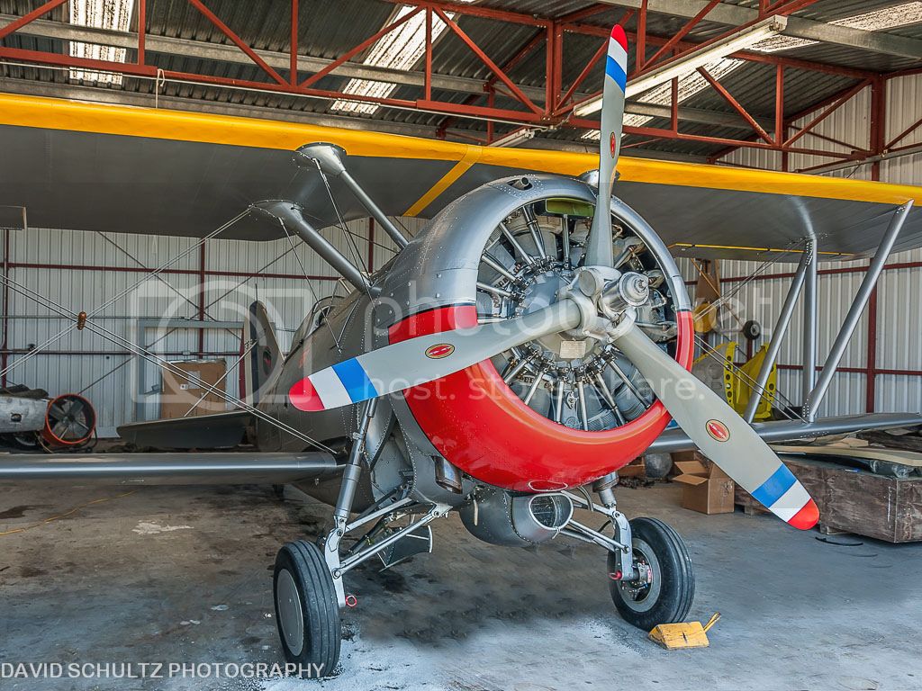
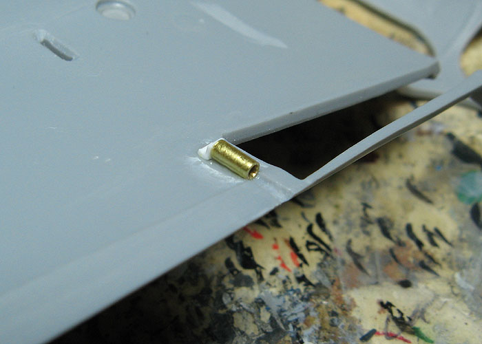
The smallest and simplest first: to make attaching the wing machine gun blast tubes nice 'n' easy during the final assembly, I made simple mounts from brass tube and L-shaped styrene channel.


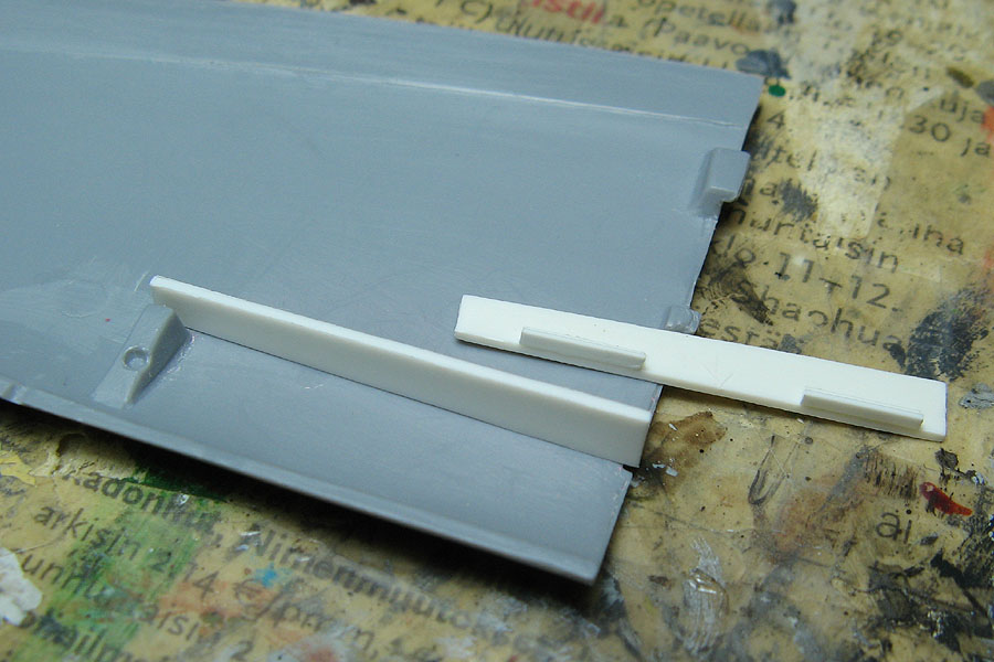
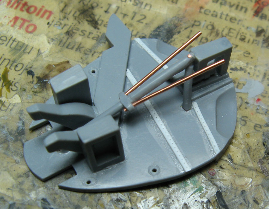
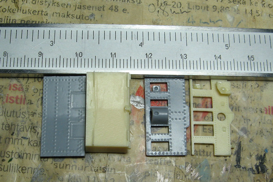
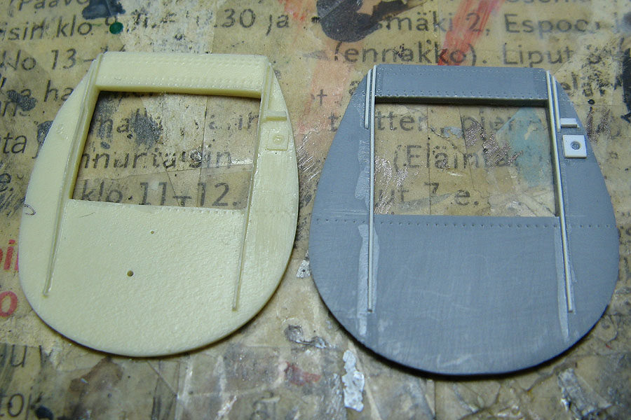
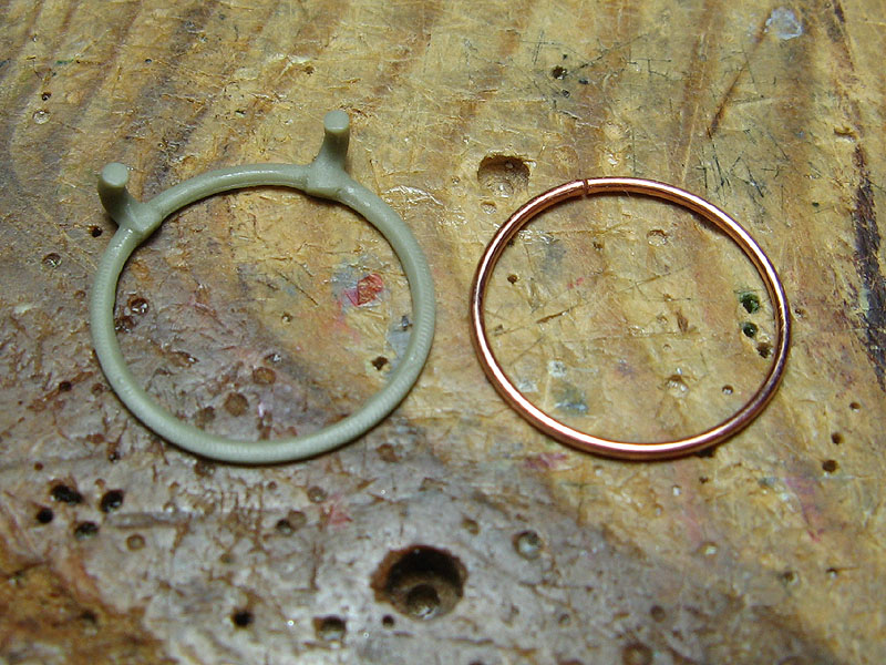
As I mentioned fiddling with the styrene and resin parts, here's one of the many areas needing attention, the seat.

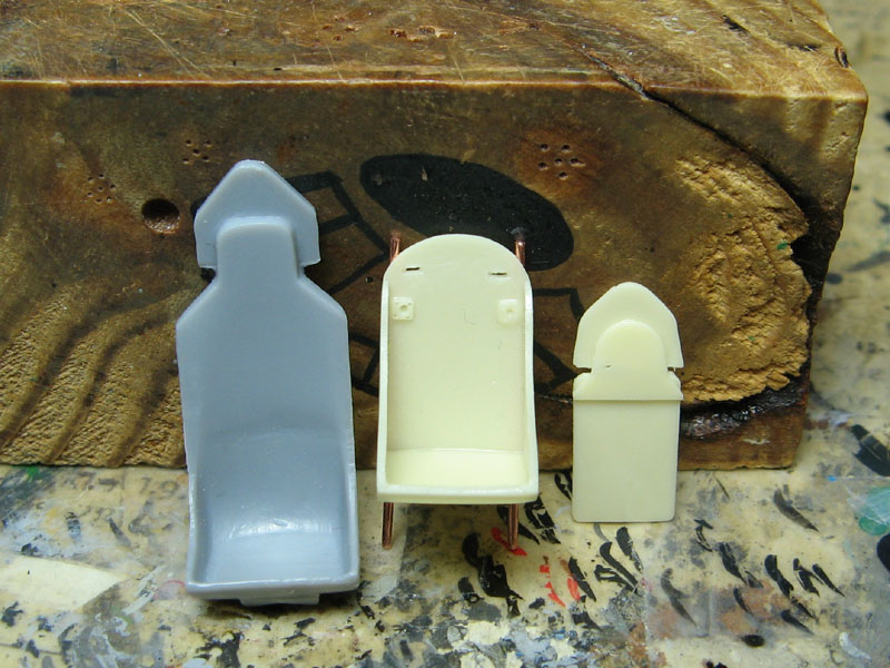
Kit seat on the left, CMK resin seat (mounts replaced with copper wire) and it's armor plate on the right. In addition to being thick like battleship plating, the CA kit part, while looking kinda, sorta like the real thing, is in the end just incorrect.
A) The extra armor wasn't integral with the seat.
B) The shape of the plate is off (should have rounded right angles instead of 45° angles near the top).
C) Head armor is separate from the back armor plate.

The seat in the CMK cockpit set is of the correct type, but the extra armor is a weird, undersized contraption, that like the CA seat, has the head armor moulded together with the back plate. Solution: use the seat - scratch-build the extra armor.

---------
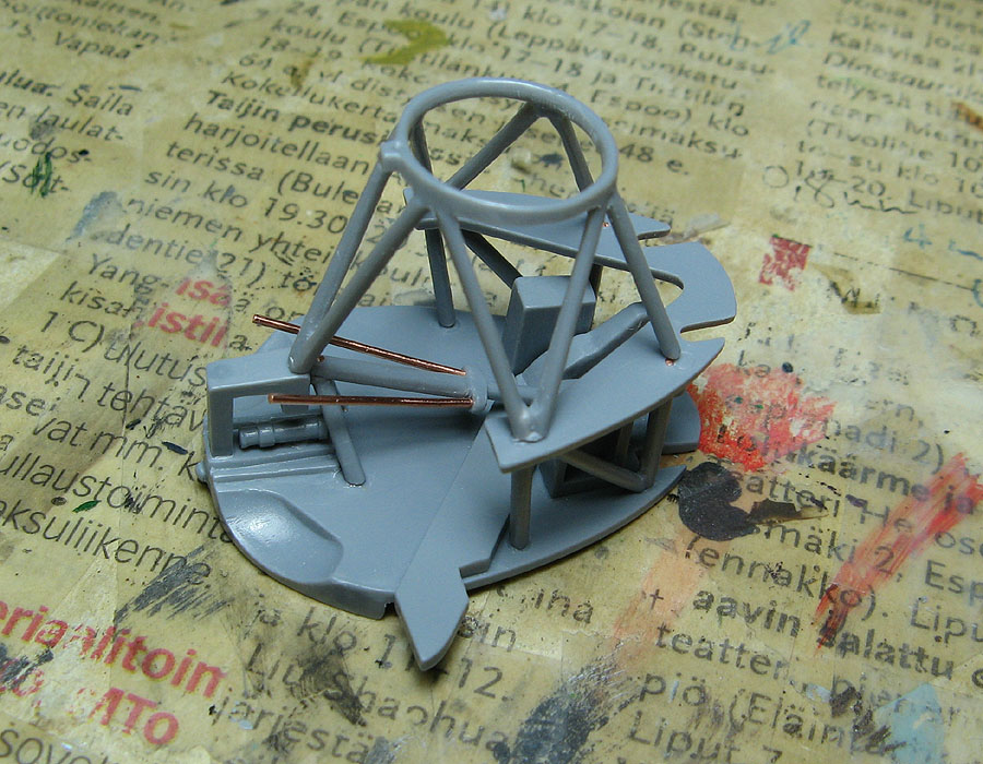
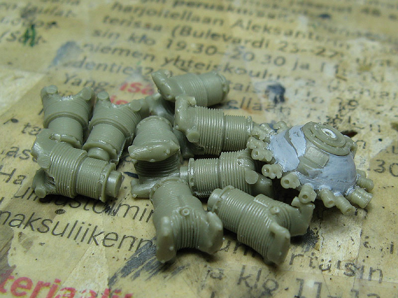
Moving on to the main part of this update: starting to figure out the engine / fuselage landing gear bay assembly, what's wrong with it, and what I plan to do about it.

One thing that has been puzzling me throughout (Well, if you can call it that... Let's say "so far") the build is the slightly raised part alignment aids moulded inside the fuselage halves. I haven't been able to quite figure out if the parts are supposed to be glued on top of them or next to them. Seems the answer is both, depending on the part.

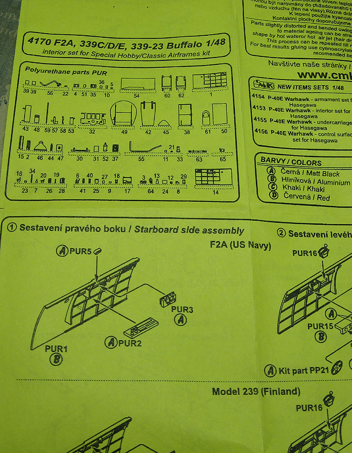
Since the kit instructions' suggested assembly sequence for the engine mount sub-assembly looked very prone to alignment mistakes and ill-fitting parts (hmm, now what a surprise that would be...), I decided to start with the most crucial and make sure the engine would be positioned correctly and sturdily enough. So, that would be the bulkhead right behind the engine.

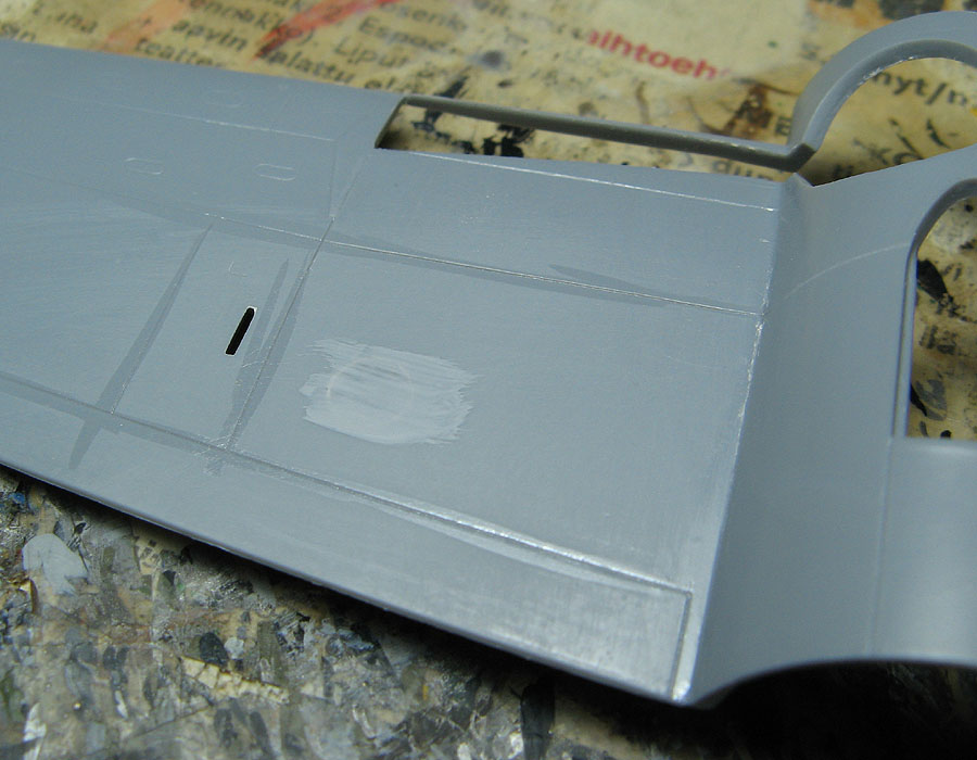
Looking at the raised alignment aids, the location of the one on the left fuselage half was very inconsistent, waving back and forth a whole millimeter from the front edge of the fuselage. The one on the right was OK, so I used that and glued styrene strip over it, then measured the distance from the front edge and glued a strip to the left side as well, before which I scraped off the useless wavy one.

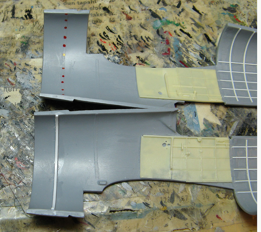
Behind the cockpit I've made a start adding some internal structure detail.

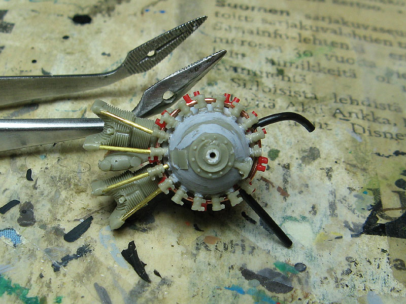
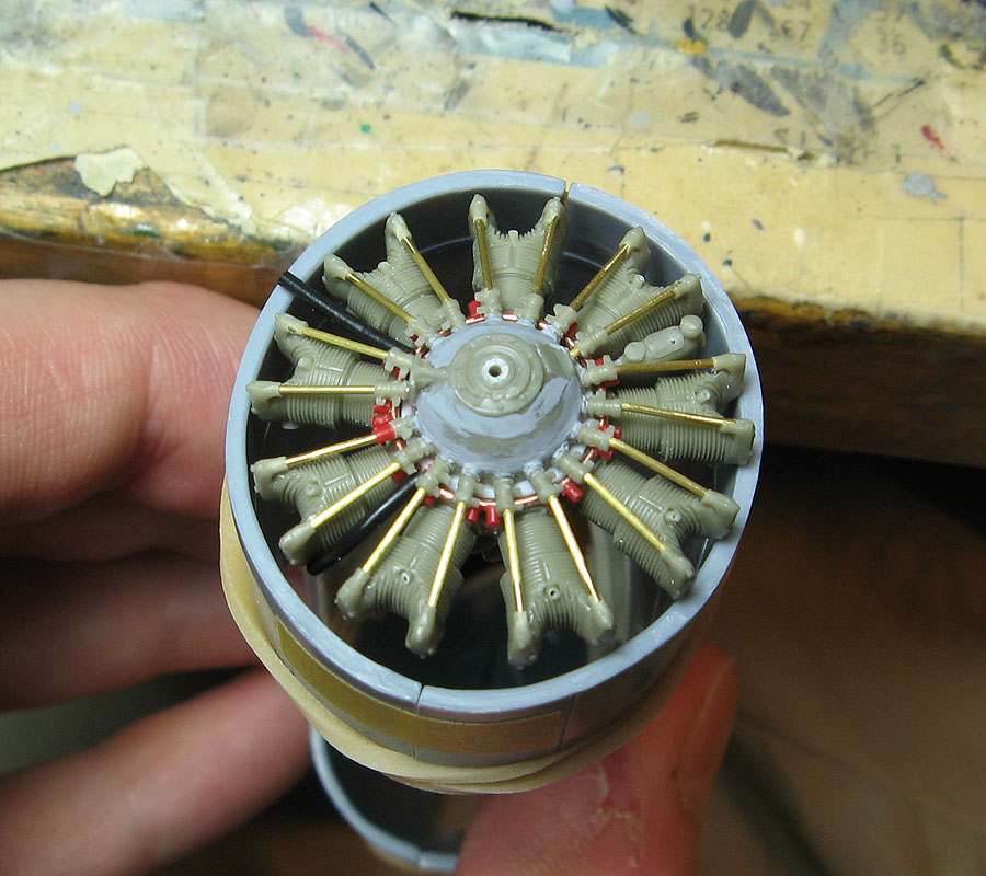
Now with proper locators for the bulkhead, a bit of sanding for the cylinder heads and quite a lot for the bulkhead (it feels like it's meant for another kit...), the engine fits in and sits where it should be, the front almost to the level of the cowling's front edge.


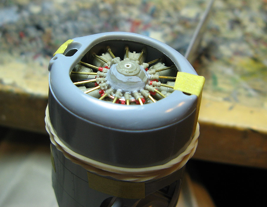
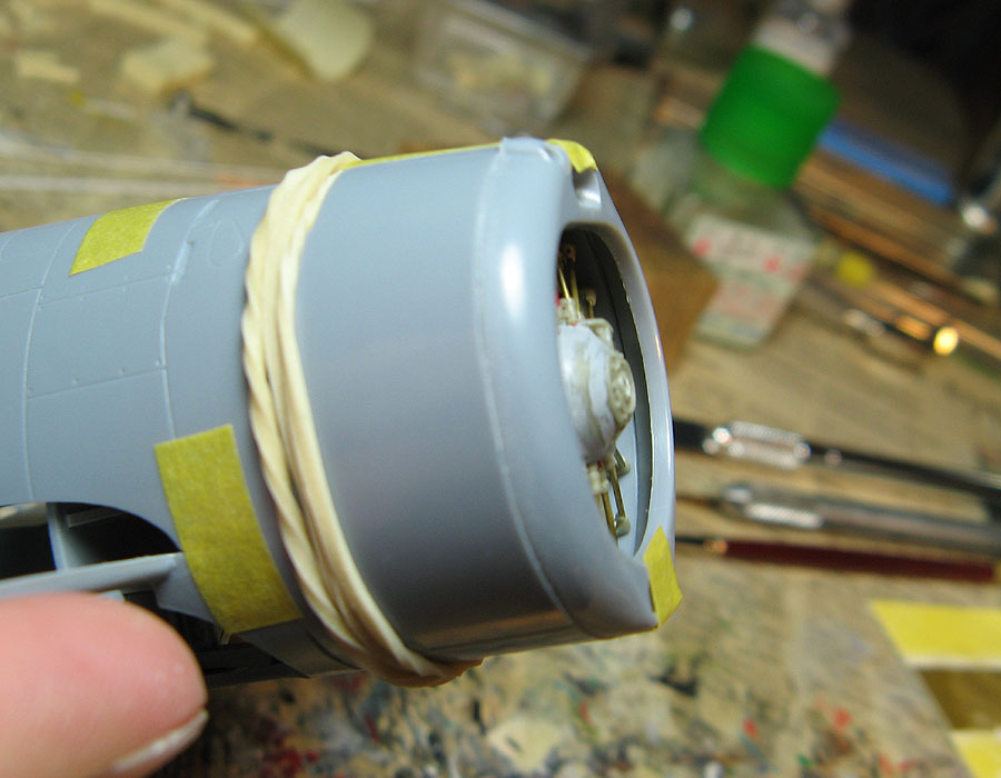
^ That's dryfitted without the exhaust collector pipes in place, so I have to glue in the front bulkhead behind the styrene strip locators to move the engine back accordingly.

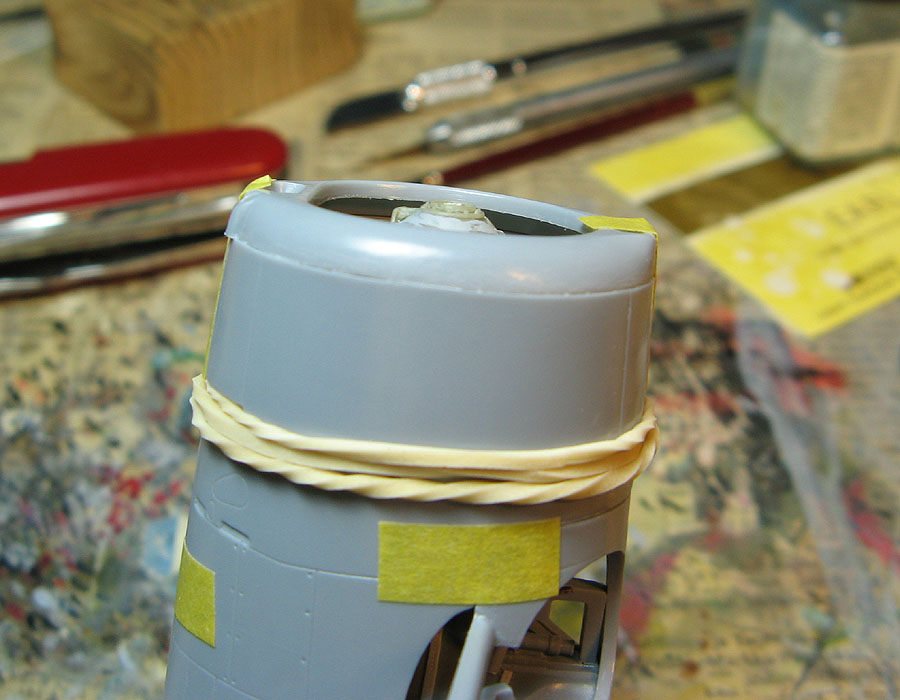
I also did some dryfitting with the engine mount assembly and figured out the reason why several build reviews of the kit reported the engine sitting too far back in the cowling. No wonder, the mount assembly is noticably too short!

(^ note the less-than-stellar match between the fuselage and the small bulkhead...)


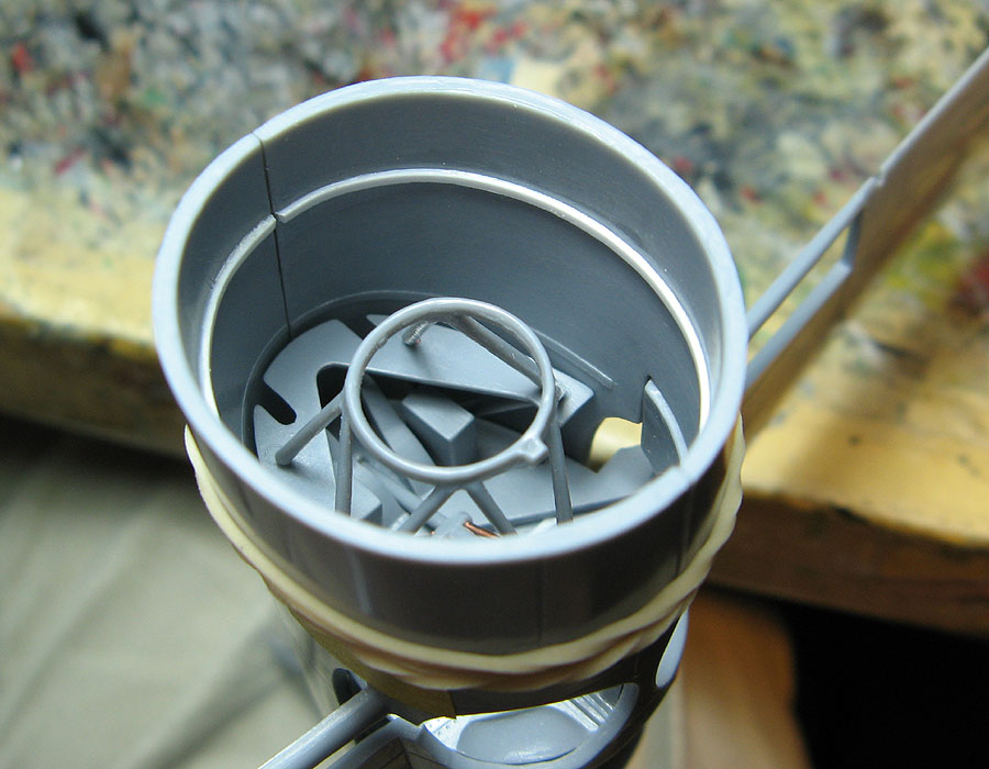
^ Here, that circular front part of the engine mount should reach the foremost bulkhead.

I was quite puzzled by this discrepancy and couldn't think of any other explanation (apart from some very sloppy workmanship and/or lack of communication between the people working on the kit) than that the engine mounts were originally made for the shorter-nosed F2A-2/3 variants!
I hadn't thought about until now, but it all makes sense. The poor-fitting front fuselage bulkheads, engine sitting too far back on B-239/F2A-1 when instructions were followed. Indeed, the same sprue D is used in all CA and Special Hobby Brewster kits!
Well done, well done indeed... This was pretty much exactly my reaction. Was it really SO hard and/or expensive to make correct engine mount parts and bulkheads for each variant and put them on the fuselage sprues which are different depending on the kit?

Heck, even the instructions show a late-variant fuselage (note the location of the holes for the exhaust pipes). Guess they had in mind to release later variants first, but the plans changed and the decision was made to just go with it instead of making expensive and time-consuming changes.
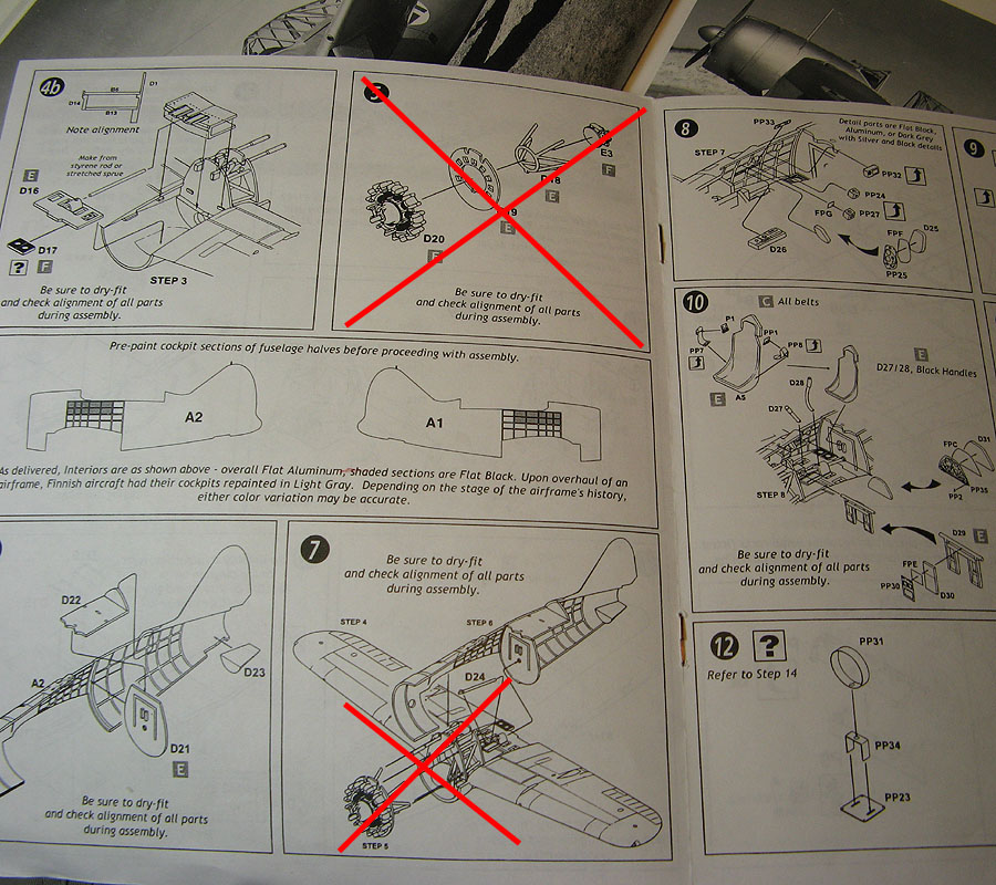

So, don't follow the instructions on mounting the engine for this or the F2A-1 kit, or you'll end up with a seriously misplaced engine.

I'll have to see if I want to be bothered to extend the engine mounts to reach the foremost bulkhead. The fuselage compartment is rather cramped and not that easily visible when finished, after all.

Redhand
#522
_VISITCOMMUNITY
New Jersey, United States
Joined: January 20, 2013
KitMaker: 1,460 posts
AeroScale: 1,443 posts
Posted: Tuesday, July 14, 2015 - 07:04 AM UTC
Your build is going to be the "go-to" reference for me when I tackle this kit. Beautiful, beautiful work.
 _GOTOTOP