_GOTOBOTTOM
Pre-Flight Check
Constructive critique of your finished or in-progress photos.
B-17G "Chowhound" Build
TotemWolf
_VISITCOMMUNITY
Oklahoma, United States
Joined: February 11, 2013
KitMaker: 294 posts
AeroScale: 74 posts
Posted: Thursday, August 17, 2017 - 07:31 AM UTC
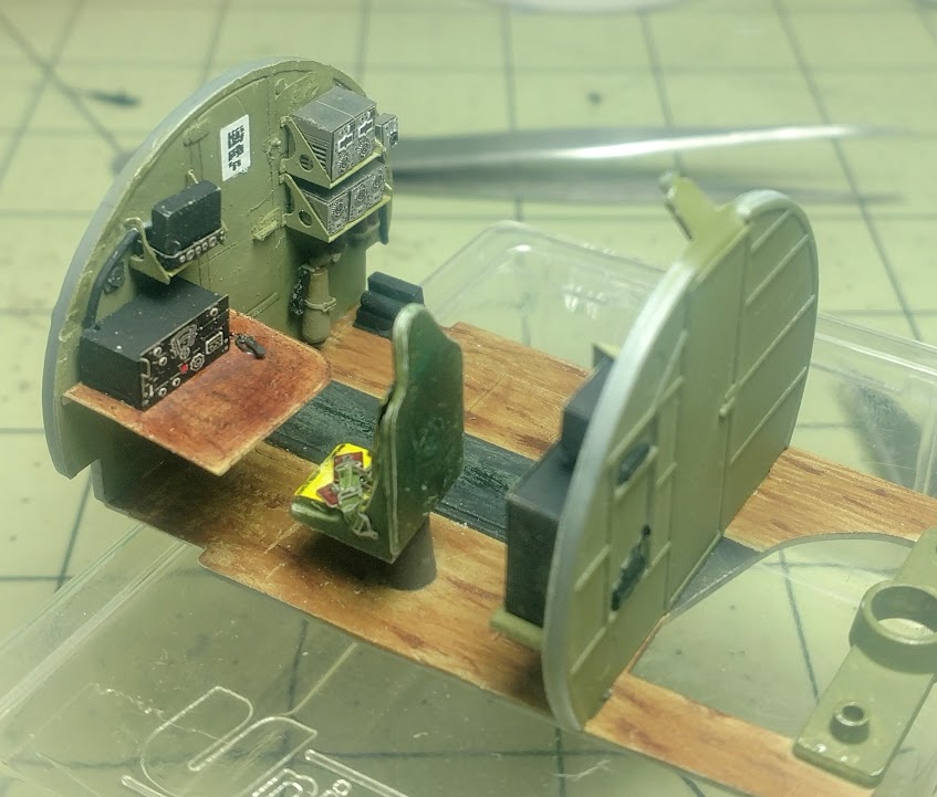
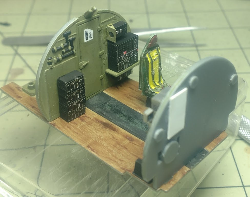
Ok so I finally got back to the bench.
I finished the little bit of PE that I needed to complete for the radio compartment itself. I also throw on some detail paint, and the decals for the doors.
Now everything is glued in place and the first part of step 3 is done.
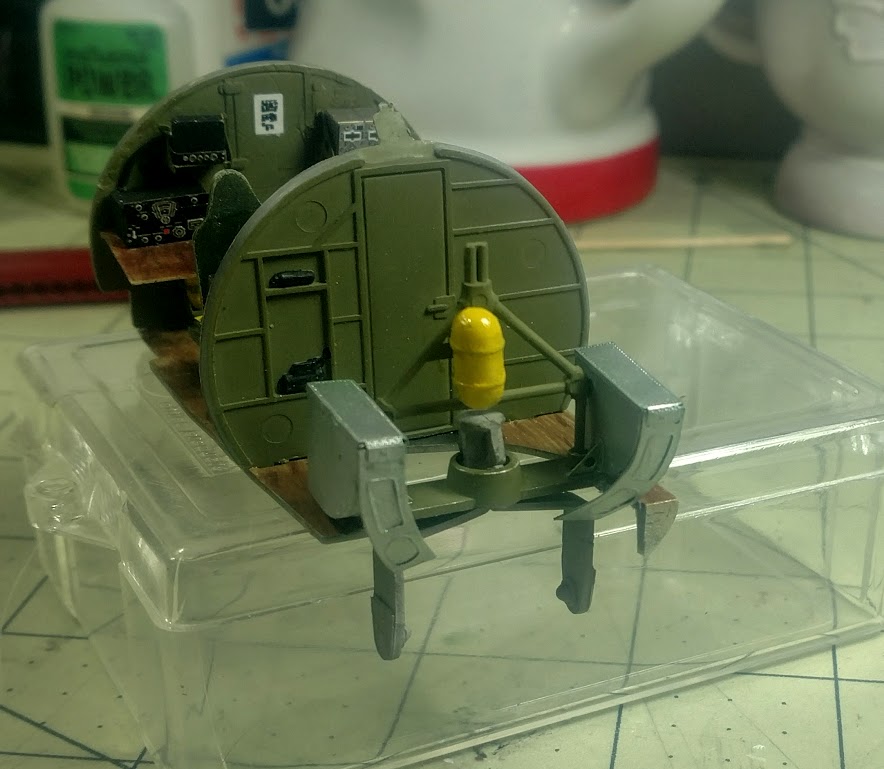
Next I’ll start working on the ball turret area.


TotemWolf
_VISITCOMMUNITY
Oklahoma, United States
Joined: February 11, 2013
KitMaker: 294 posts
AeroScale: 74 posts
Posted: Wednesday, August 23, 2017 - 06:43 AM UTC
Well I’m back to it and things are plugging along.
I’m got the ball turret mechanism finished. I started to work on it last week and I did get the ammo dispensers put together but had to stop there. I did some research on what the mechanism looked like in an operational B-17. Without completely modifying the model it would have been impossible to replicate the exact look, so I settled for the best I could do with what I have. Also once the plane is complete what can be seen from the doorway in the windows will be very close to correct. There are two more small pieces of PE that were added to the dispensers after this photo but I didn’t think it was worth getting another photo. Once it is in place and before closing up the fuselage I will get more pictures.

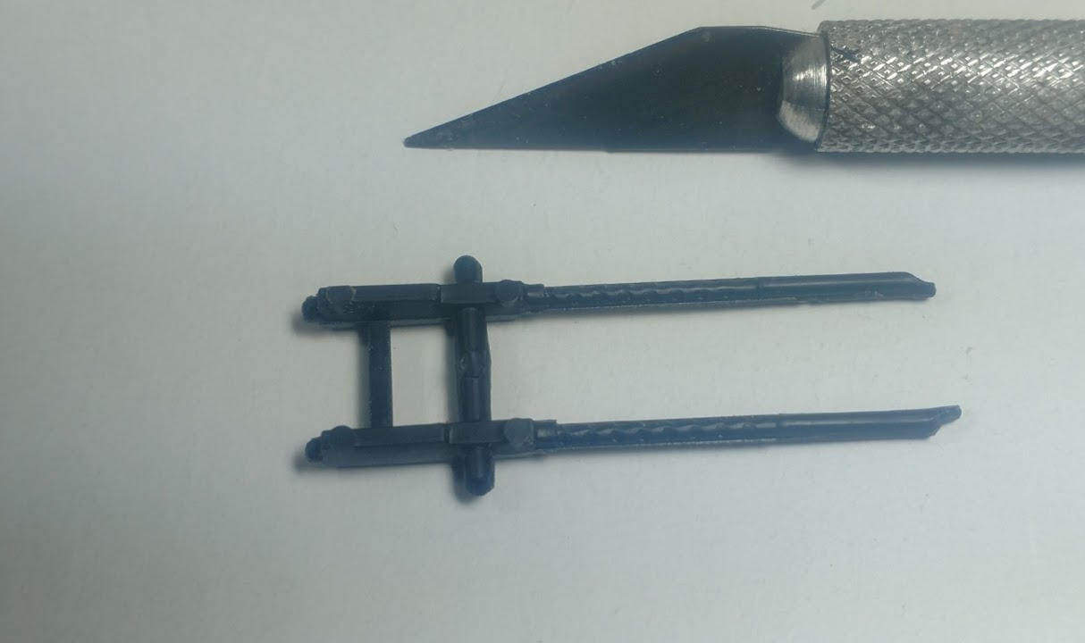
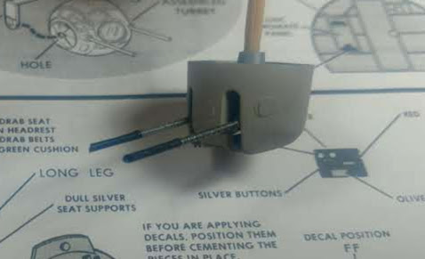
I also managed to start working on the chin turret. This is what the guns looked like.

….. and yes those pin marks are visible when the turret is complete. Why couldn’t they just put them on the other side where they would never be seen? You have to love “That 70’s Plastic.”

I went ahead and used the PE barrels and flash guards. They are placed on a 0.8mm core that was glued to the gun via on hole I drilled after removing the stock barrels. In the end I think it came out alright. I don’t think the extra cost for brass or resin would make enough difference to justify the price since I had already paid for these.

I have starting prepping the deck for the cockpit the nose section. I have it ready to start adding a lot of extras. So that’s where the build is heading next, and by the looks of things it should be a fun ride.
TotemWolf
_VISITCOMMUNITY
Oklahoma, United States
Joined: February 11, 2013
KitMaker: 294 posts
AeroScale: 74 posts
Posted: Friday, August 25, 2017 - 12:46 AM UTC
Well I ran into my first good size roadblock. I want to have the front emergency exit door open on the aircraft. That is the one you see the flight crew climb into in movies like “Twelve O’clock High.” Of course this is on the bottom of the aircraft just beneath and flight controls, and on the kit there is NO detail there. In fact it is completely hidden. I don’t mind building the interior from scratch but I need some good references. Does anyone have any? Thanks for the help in advance.
KPHB17FE
_VISITCOMMUNITY
Illinois, United States
Joined: January 12, 2015
KitMaker: 292 posts
AeroScale: 292 posts
Posted: Friday, August 25, 2017 - 07:11 AM UTC
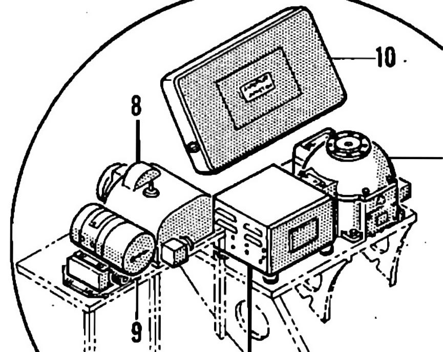
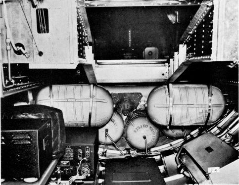
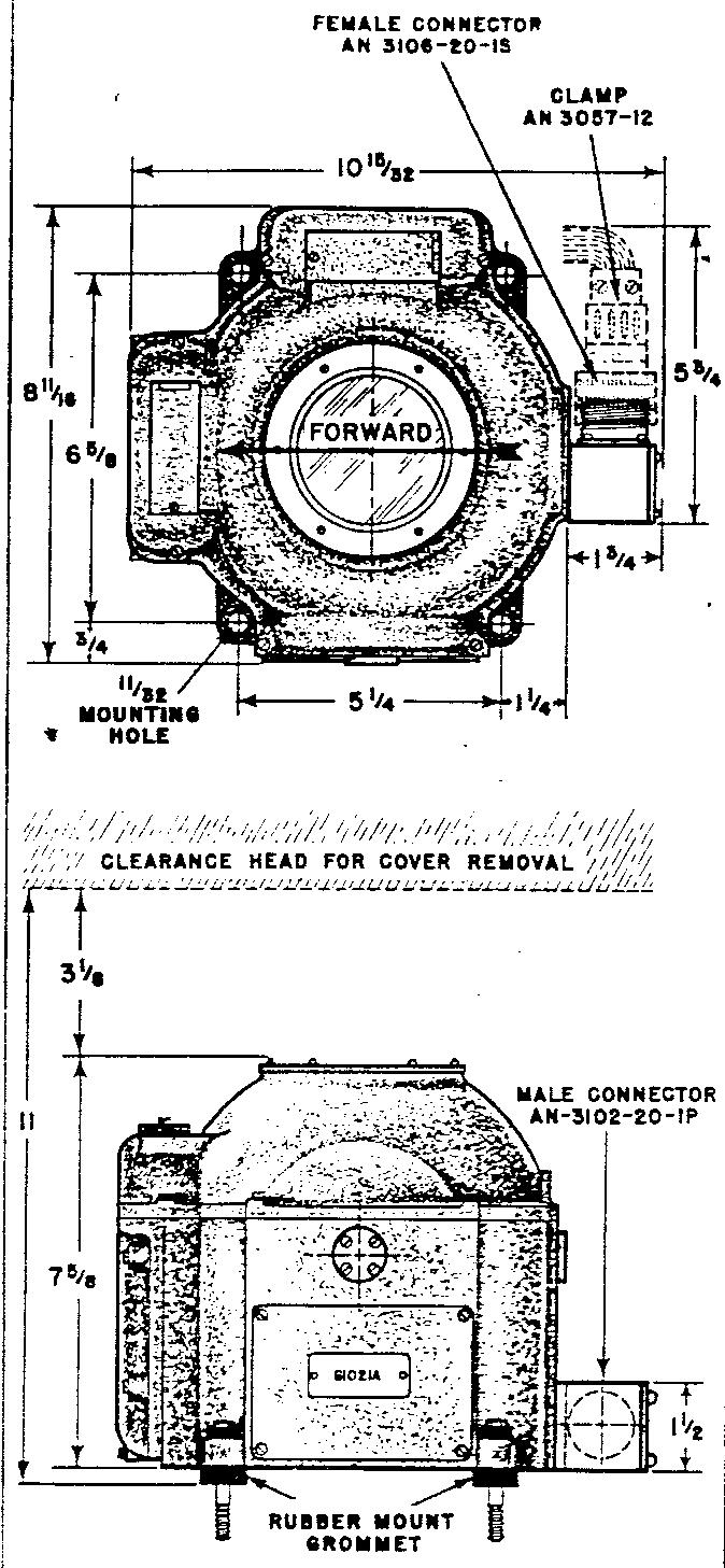
Directly across from the entry hatch were these autopilot components:


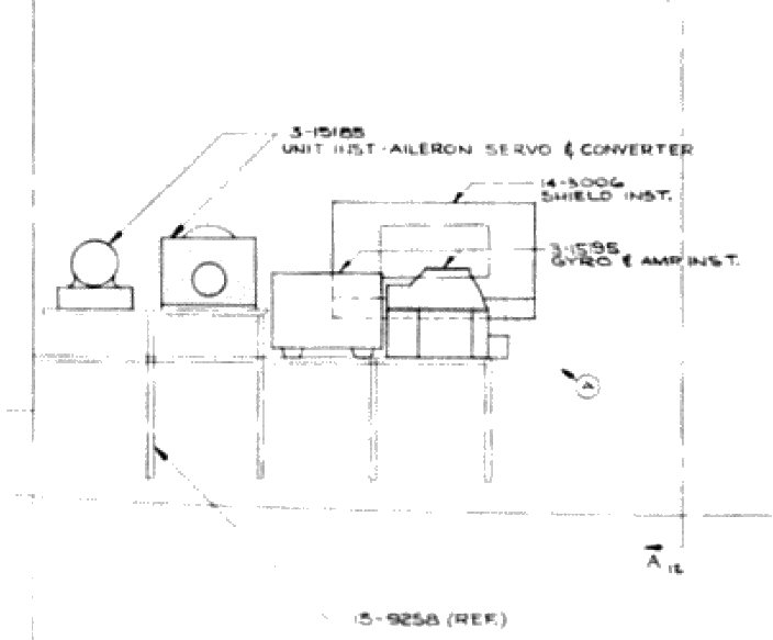
Here is drawing of them as viewed from the hatch:


Here is a view looking aft from the navigators position. You can see a couple of the AP components (the gyro has a heated blanket covering it) as well as the oxygen bottles under the top turret area. The black box aft of the AP components is the Radio COmpass receiver. The box to the lower right of the photo (A/C left) contained the voltage regulators:


KPHB17FE
_VISITCOMMUNITY
Illinois, United States
Joined: January 12, 2015
KitMaker: 292 posts
AeroScale: 292 posts
Posted: Friday, August 25, 2017 - 07:28 AM UTC
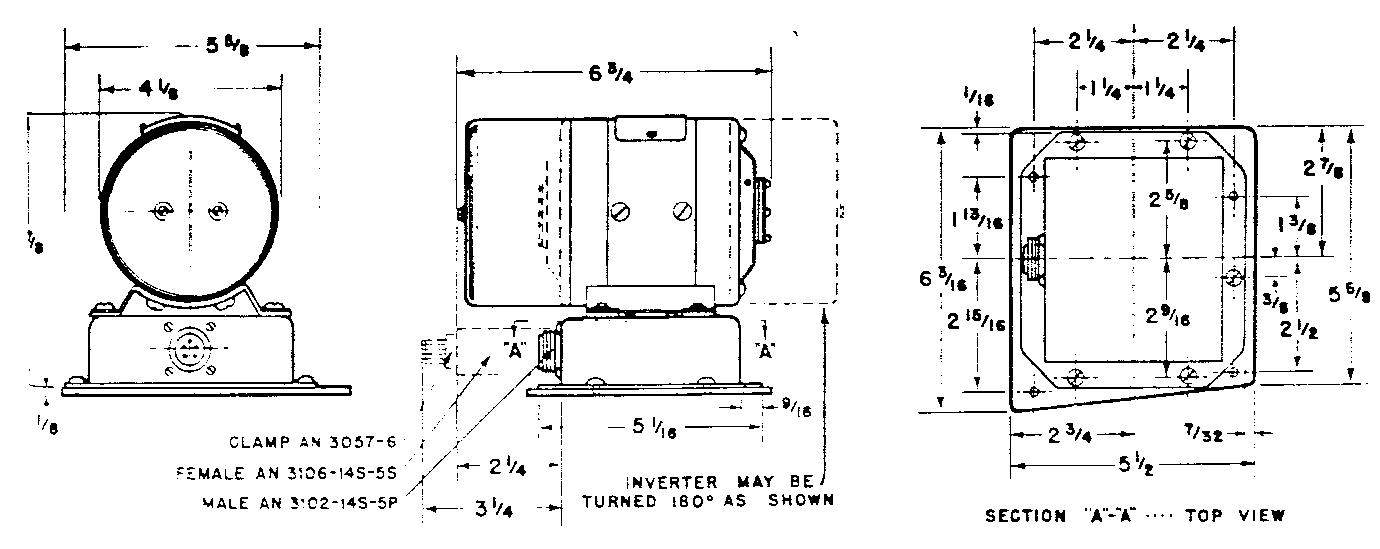
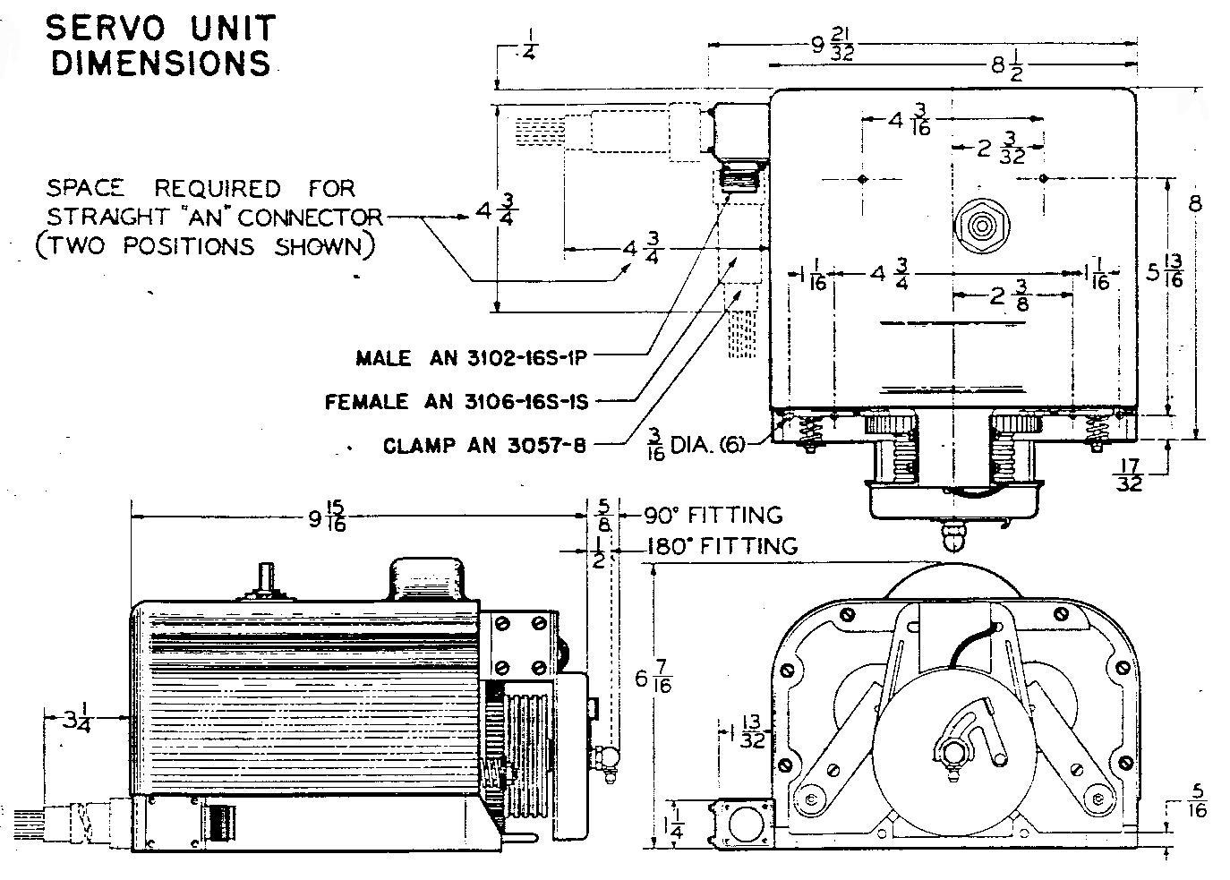
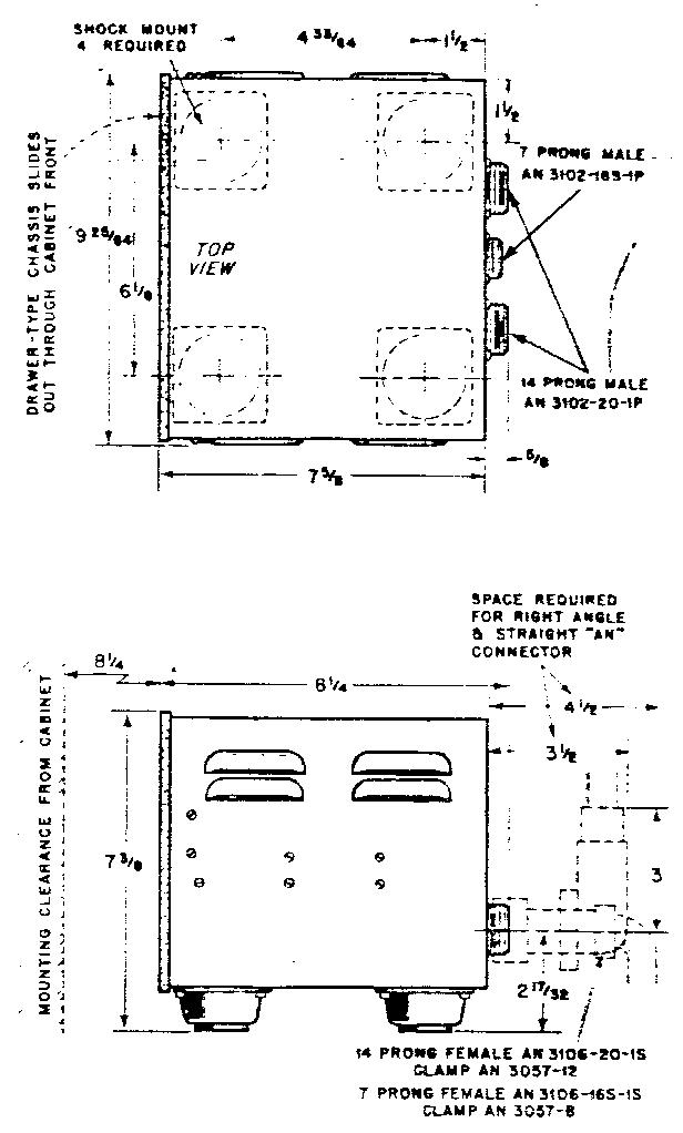
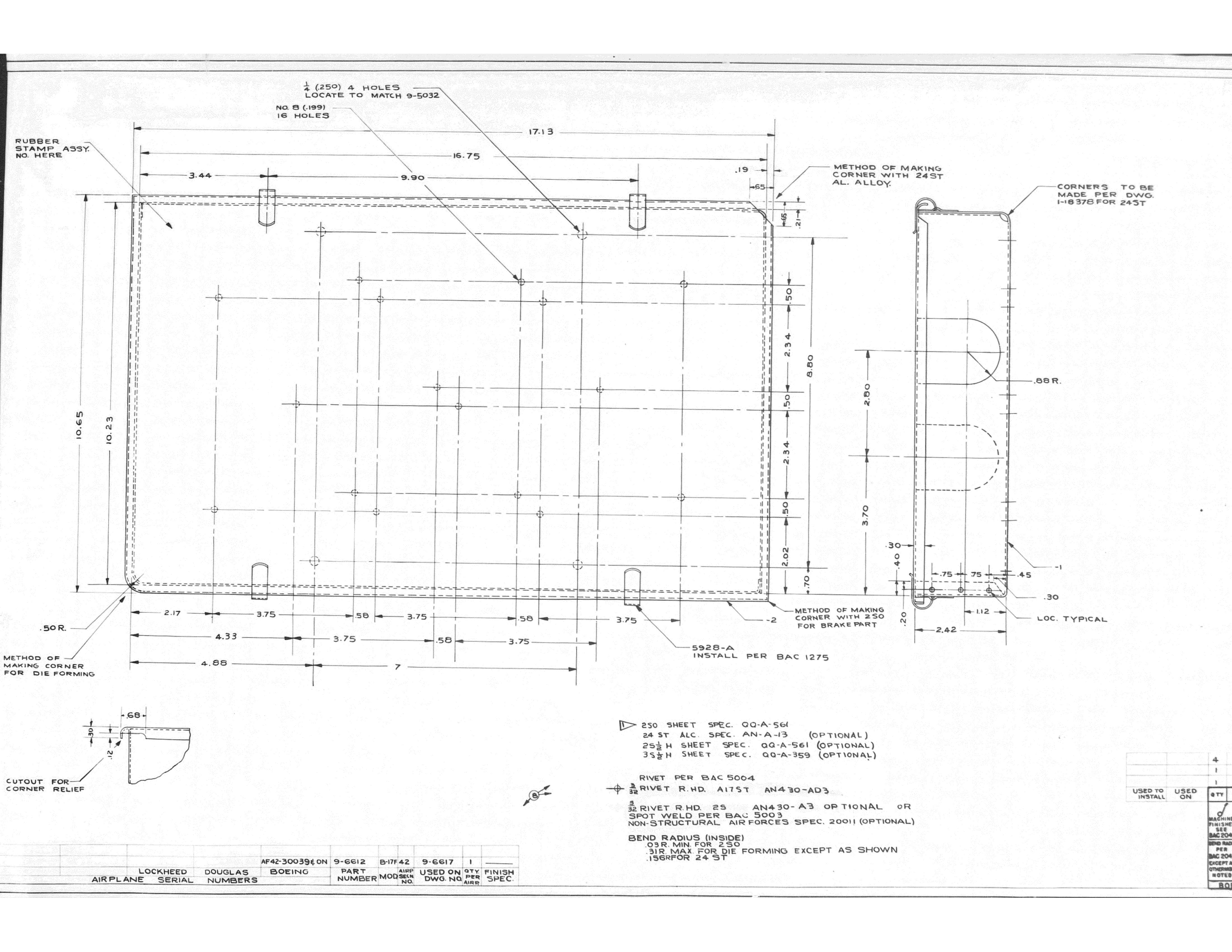
Autopilot components:

Converter:


Servo:


Amplifier:


Gyro:


Shield:

TotemWolf
_VISITCOMMUNITY
Oklahoma, United States
Joined: February 11, 2013
KitMaker: 294 posts
AeroScale: 74 posts
Posted: Friday, August 25, 2017 - 07:41 AM UTC
Thanks that added to the little bit that I found should help fill it in perfect.
TotemWolf
_VISITCOMMUNITY
Oklahoma, United States
Joined: February 11, 2013
KitMaker: 294 posts
AeroScale: 74 posts
Posted: Friday, August 25, 2017 - 07:47 AM UTC
I had a good day at the bench and on the computer today. I did some digging and found some good reference photos; unfortunately none of them except one very unclear shot showed the area near front crew door. There were a couple of schematics plus what Karl posted that will help me later when I start to tackle that area.

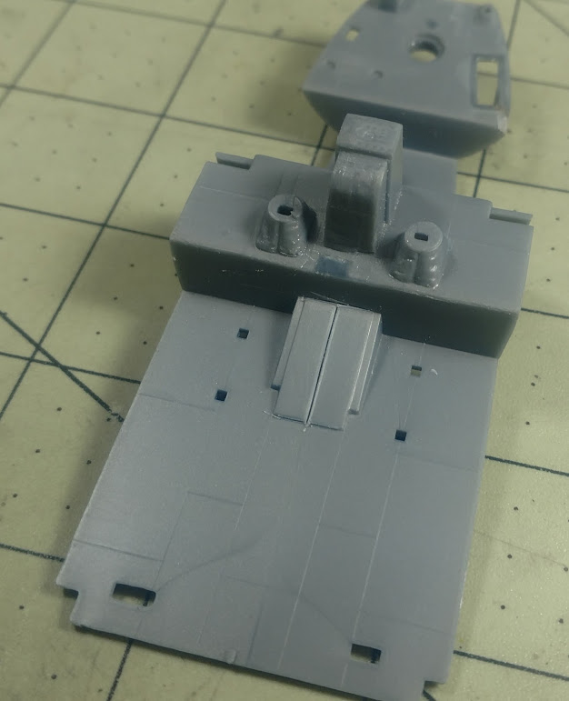
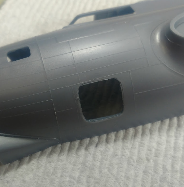
I decided to go ahead and open up the doors from both the nose section and the cockpit to the emergency exit. Here are a couple of before photos that show what they looked like in the kit. The nose section just had and fake curtain over the opening.


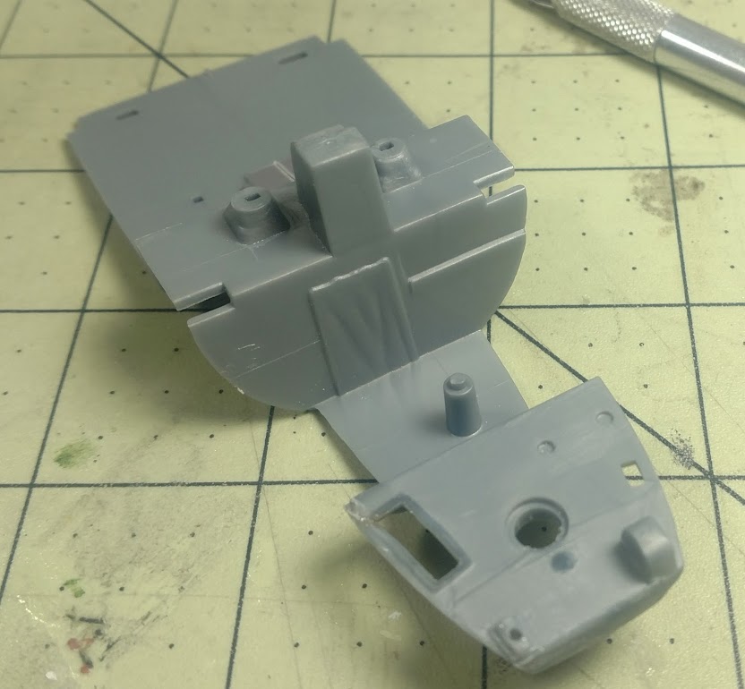
Here’s the cockpit with the opening cut out and scratch-built doors installed, also one of the nose section opened up.


After dry fitting the deck and looking at where the door would open I realized I would need to extend bulkhead 3 and place a bulkhead under the cockpit just beyond the cockpit entrance.

I should now be able to work out exact what will be placed in the area when I get the deck in place in the fuselage.
Next I’ll paint the deck and start completing the cockpit and nose section.
TotemWolf
_VISITCOMMUNITY
Oklahoma, United States
Joined: February 11, 2013
KitMaker: 294 posts
AeroScale: 74 posts
Posted: Friday, August 25, 2017 - 08:05 AM UTC

Quoted Text

Autopilot components:

Converter:

(img removed)

Servo:

(img removed)

Amplifier:

(img removed)

Gyro:

(img removed)

Shield:

(img removed)


Wow

Some of those are going to scale down to just a couple of mm. I might doing some sculpting.
KPHB17FE
_VISITCOMMUNITY
Illinois, United States
Joined: January 12, 2015
KitMaker: 292 posts
AeroScale: 292 posts
Posted: Friday, August 25, 2017 - 04:36 PM UTC
A couple of minor inputs if I may: The doors between the pilots seats were removed from combat aircraft. A little detail on that, they were not two separate doors but rather a bifold door that hinged on the aircraft right. And combat B-17's did not have the external cans on the ball turret. Yes, I know some of the aircraft flying have them but there aren't any WWII photos showing them in use and several veteran ball turret gunners I have spoken to had never seen them before. One more little detail, that bulkhead you have under the turret floor should be back at the bomb bay. Unless you are just doing that for your convenience. Not a slam, just if you want to add the O2 bottles, they won't fit.
TotemWolf
_VISITCOMMUNITY
Oklahoma, United States
Joined: February 11, 2013
KitMaker: 294 posts
AeroScale: 74 posts
Posted: Friday, August 25, 2017 - 07:04 PM UTC

Quoted Text

......... One more little detail, that bulkhead you have under the turret floor should be back at the bomb bay. Unless you are just doing that for your convenience. Not a slam, just if you want to add the O2 bottles, they won't fit.


Yeah, I think I might have to put it there because of the wings. Once I'm close to the final assembly I may see if I can do something about that. The more I get into the build the more compromises I am going to have make. In the end what I want is something that will look as good as possible and as real as possible in scale from the viewpoints allowed, but will still be fun to build.

Having said that please keep making suggestions. I will defiantly use what I can.
TotemWolf
_VISITCOMMUNITY
Oklahoma, United States
Joined: February 11, 2013
KitMaker: 294 posts
AeroScale: 74 posts
Posted: Friday, August 25, 2017 - 07:10 PM UTC
I found some more reference material that will help.

KPHB17FE
_VISITCOMMUNITY
Illinois, United States
Joined: January 12, 2015
KitMaker: 292 posts
AeroScale: 292 posts
Posted: Friday, August 25, 2017 - 07:53 PM UTC
Just floating an idea here: You could paint that bulkhead black and just put the ends of the O2 bottles on it. That would fool the eye for no more than can be seen through the hatch. With the two hanging from the floor, visibility would be limited as well.

Some B-17's had the engine fire extinguisher bottles located there. These are seen on several of the currently flying birds so people tend to include them in all builds (those that detail that area anyway ). But the engine ext system was deleted from the early G models. When the system was initially reinstalled, the bottles were in the right wing root. The bottles were not located under the cockpit until the G-80-BO block (43-38074 and on). Not relevant to "Chowhound" but just in case someone pops up with a photo showing those bottles.

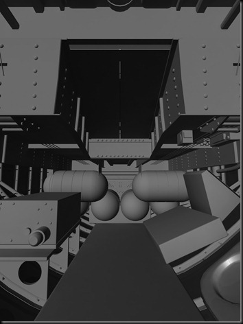
Is the cad rendering you have posted of th HK kit?
TotemWolf
_VISITCOMMUNITY
Oklahoma, United States
Joined: February 11, 2013
KitMaker: 294 posts
AeroScale: 74 posts
Posted: Friday, August 25, 2017 - 08:04 PM UTC
As far as the ammo cans, this comes from page 122 of a Sperry manual on the turret.


Quoted Text

"Two ammunition cans, which are a permanent part of the turret ball, one for each gun, hold approximately 500 rounds of belted ammunition apiece. In some late modifications of the turret the ammunition cans are placed outside the turret, mounted to the hanger assembly, to give the gunner more room; flexible chutes carry the ammunition belts from the cans to the turret and guns. But most Sperry Ball turrets still have cans installed right in front of the gunner. They cannot be removed from the turret and must be loaded from the outside."


They may or may not have been in the 'Chowhound,' more than likely not; but as the turret area is so sparse on the kit I may leave them just to hide the weak representation of the turret mechanism.
TotemWolf
_VISITCOMMUNITY
Oklahoma, United States
Joined: February 11, 2013
KitMaker: 294 posts
AeroScale: 74 posts
Posted: Friday, August 25, 2017 - 08:15 PM UTC

Quoted Text

Just floating an idea here: You could paint that bulkhead black and just put the ends of the O2 bottles on it. That would fool the eye for no more than can be seen through the hatch. With the two hanging from the floor, visibility would be limited as well.

Some B-17's had the engine fire extinguisher bottles located there. These are seen on several of the currently flying birds so people tend to include them in all builds (those that detail that area anyway ). But the engine ext system was deleted from the early G models. When the system was initially reinstalled, the bottles were in the right wing root. The bottles were not located under the cockpit until the G-80-BO block (43-38074 and on). Not relevant to "Chowhound" but just in case someone pops up with a photo showing those bottles.

Is the cad rendering you have posted of th HK kit?


Yep, that's right along the lines I was thinking.
I will try fitting the wings see how much more I can push it back. I might place like half a bottle on the 'bulkhead' or something.
Also I have not removed the door yet so I'm not even sure what will be visible. Even without all of the equipment in the nose or cockpit you can't see much detail in the area through the deck openings so even something as simple as panting of details might work from that viewpoint. Even more so when the gear in both areas is added.
TotemWolf
_VISITCOMMUNITY
Oklahoma, United States
Joined: February 11, 2013
KitMaker: 294 posts
AeroScale: 74 posts
Posted: Wednesday, August 30, 2017 - 01:20 AM UTC
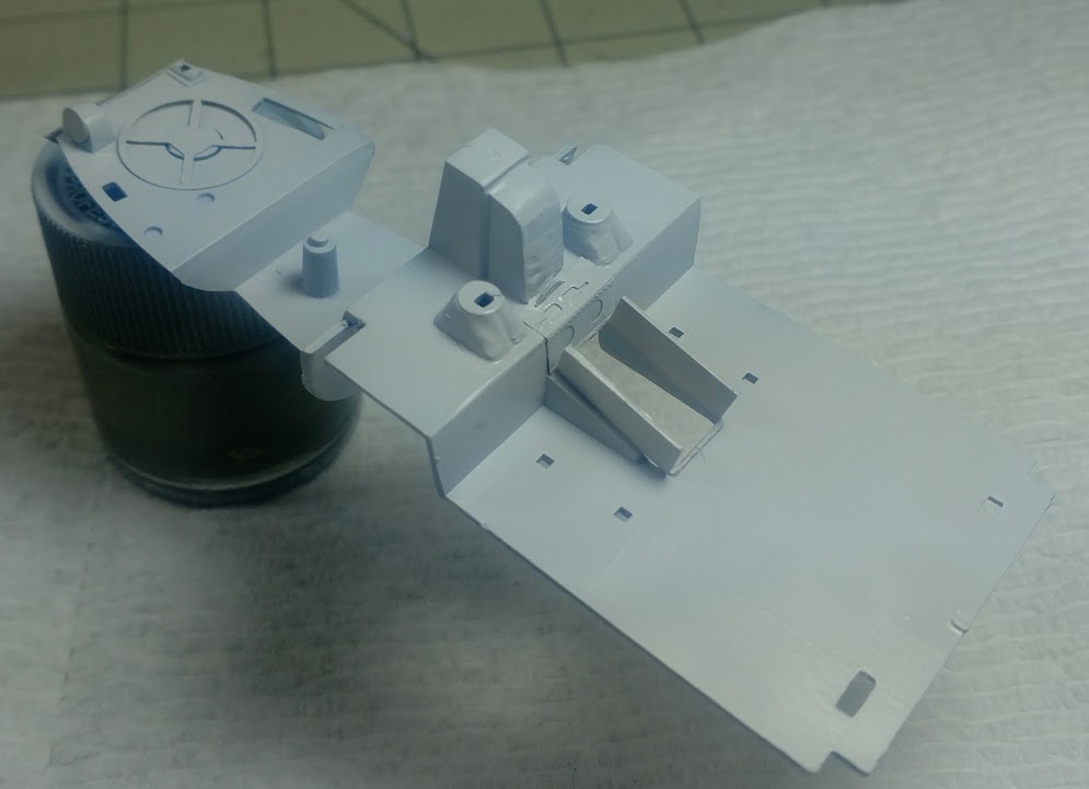
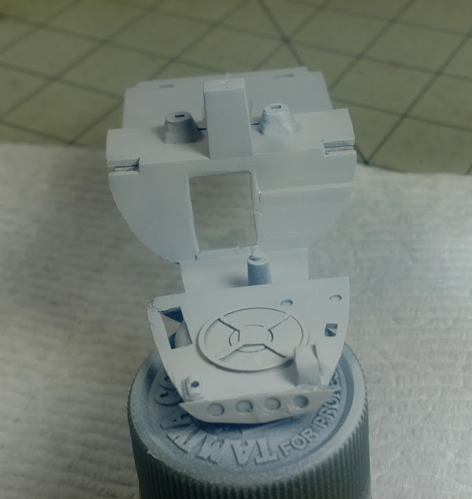
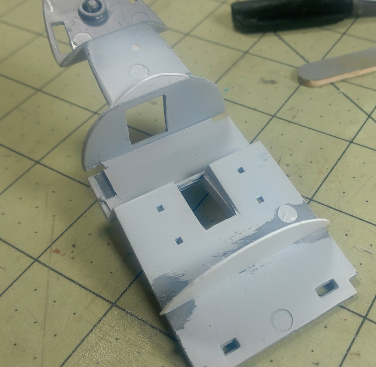
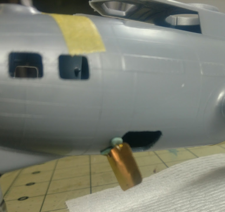
I went ahead and opened the forward exit.

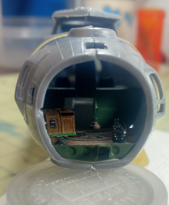
I also painted the front deck and started to assemble some of the basic components just so I can get an idea of what I will be working with in regards to the area under the cockpit. After dry fitting it into the fuselage this is what can be seen.


It looks like most of the area will be obscured. A few details maybe needed near the door itself, but at scale, fully assembled even that will not be seen much at all. So I will move back to the nose interior and cockpit for now.

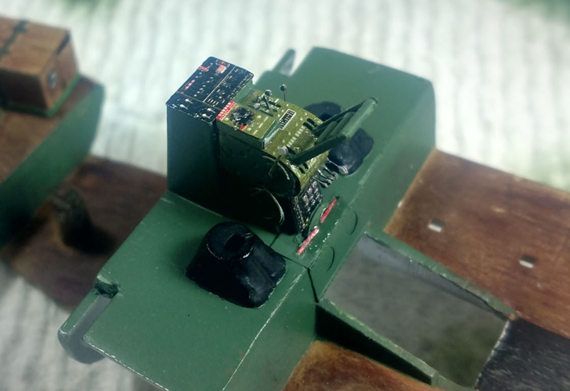
I removed the kit nose section ammo box and the details on the center controls in order to install the PE. I went ahead and removed the cockpit emergency exit doors I had incorrectly placed. The whole thing, along with the ammo box was primed and painted. Next all the PE parts that go into the area are put in place before I can even start working on the kit parts.

I think I’ve gone cross-eyed getting all the tiny, fiddley levers in place. They do add a nice touch to the controls. I just hope it’s worth it when the plane sealed up.


While reviewing the parts for the rest of this step I found a callout for kit parts 49 and 50 to build the Norden bombsight. I could not find part 49 anywhere on the sprues. I couldn’t even find the tab where it should be. On the PE instructions it shows both parts as well. A closer look at the illustration in the instructions let me see that part 49 is not shown. After some digging online I found out that the parts are now molded as one piece but the written directions have not changed. So the newer kits only have part 50 even though part 49 is called for.

TotemWolf
_VISITCOMMUNITY
Oklahoma, United States
Joined: February 11, 2013
KitMaker: 294 posts
AeroScale: 74 posts
Posted: Thursday, August 31, 2017 - 03:09 AM UTC
They say that solving puzzles will help keep your brain young and thus improves your general health. If that is the case then this build is going to add ten years to my life.

I worked on the pieces and subassemblies that will go into the nose and cockpit area so that they can be painted and then put into place for final assembly. There is a lot of flash and pin marks to be removed for every part in this kit. Once I worked my way to bulkhead 3/instrument panel, I had to figure out exactly what can be placed before I place the assembly on to the deck and what might need to wait for fear of breakage. I will have built this aircraft in my mind a dozen times over before I finish the actual build. That’s good though. Not only will it help me build the best model I can; I will learn so much about how and why I do certain things the way I do them.

Prep of the control yolk was pretty straight forward. Just seam lines and one pin mark on each yolk that needed attention.
After I discovered the problem in the instructions, the bombsight just needed a little cleaning. They have improved the details of the bombsight so two of the PE parts are not needed as they are nicely molded on the new part.
Other than the VERY niggly PE parts the chin turret control also was no problem. I did have trim the base of the controller to make it look correct as it will be in the stored position.
The instrument panel required a good amount of prep. I had to sand down the molded panel details but also remove the rudder pedals. To ensure the right amount was removed I had to dry fit the assembly and measure the bottom of the panel. If I did it right the rudder pedals should now fit just right. On bulkhead 3, a couple of the details were removed to make way for PE parts.

I’ll post pics after I have all the prep work done.
 _GOTOTOP