I have build the model very straight from the box. The cleaning of parts was rather symbolic as I was afraid of loosing the out-of-box character of the assembly process. I omitted the tiniest photo-etched parts as using them on this level I consider as simply pointless.
As the foreword is always written when the author already knows what's in the following paragraphs I would like to ask you for not discouraging and getting feeling that this kit consists only from weaknesses and problems. There are more straightforward and non-problematic steps than errors and steps which require special care and attention. But if something is straightforward what to talk about? I hope that from all this griping and complaining on the kit weaknesses you won't get the feeling that this a bad model. I want to give you a fair description of potential problems and save you some time for inventing the wheel once again.
Wings
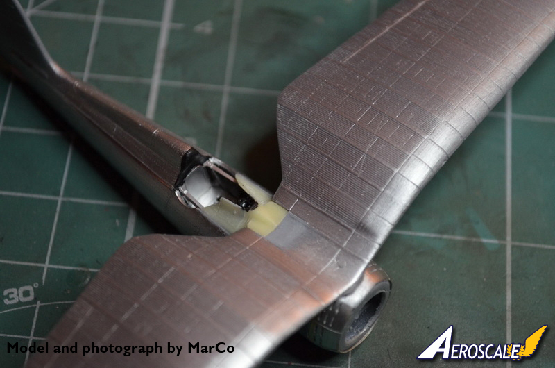
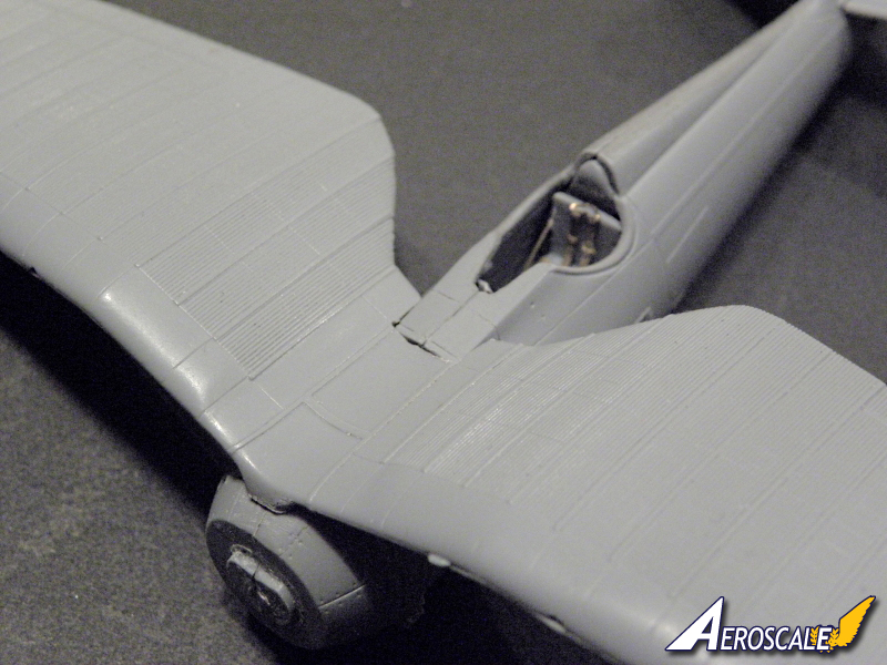
All parts for the wings are taken from the already known kits of the Azur's PZL P.24. Its shape and dimensions are the same for P.11 and P.24 but the differences and accuracy are hidden in details. First of all the P.24 had different fuselage and windscreen so the whole area of wing and fuselage joint in front of the windscreen is wrong for the P.11 kit. As far as I'm aware modellers try to adopt this section from the ancient kits from PZW Siedlce/ZTS Plastyk and make the home-made transplantation surgery, which results are usually very good. In attach you can find an image of one of this correction made by a fellow modellers from Poland Marek. He has removed the part of a fuselage from the AZUR kit and replaced it with the insert taken from the PZW/ZTS kit which has the correct shape. Another issue are raised fins on the wing upper surface. These details should be of course flat on upper surfaces and raised only on lower surface as the imitation of the metal sheets junctions. Another error are the inspection panels of the armament. There are quite significant differences in the armament between P.11c and P.24's so this is of course wrong for our kit. You can try to correct it but almost for sure you will damage the delicate imitation of the crimp surface which looks very nice. You can read a lot about most of these problem in the in-box reviews but the pure out-of-box assembly reveals few more problems. You will have to pay some attention to sanding and trimming both the leading and trailing edges as the joint surfaces of the upper and lower halves have the tendency to be rounded along the edges. Especially on trailing edge it makes the impression of thickness and won't look good after just filling with putty. You will have to do whatever is possible to make the trailing edge as fin as possible to achieve good result. It won't be difficult but for sure is time consuming and will require many fittings. This is child easy to remove, just place the sanding paper on the flat base and grind it a bit. Except this glitch the overall fit is good, there are absolutely no other excesses or trimming required.
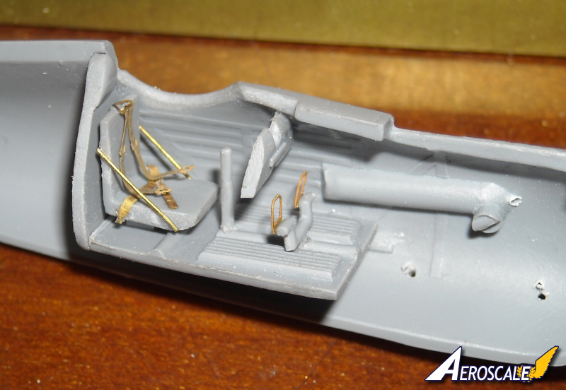
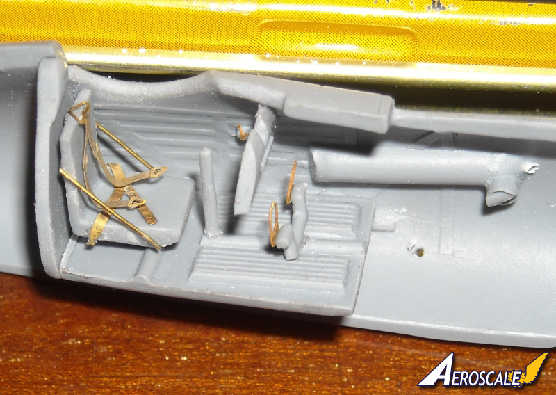
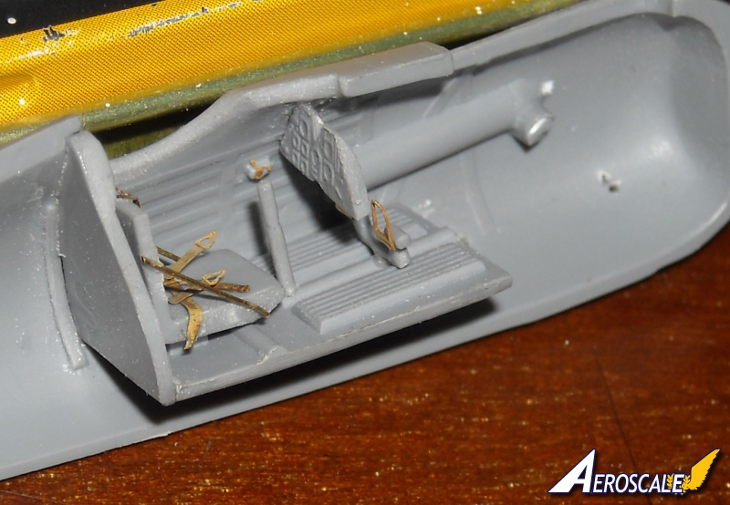
Fuselage and pilot's office
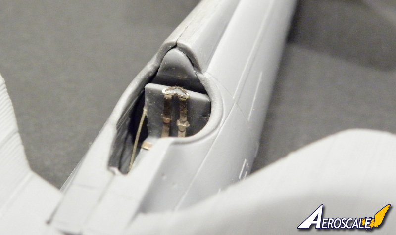
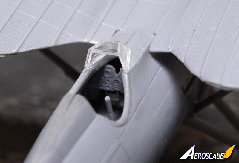
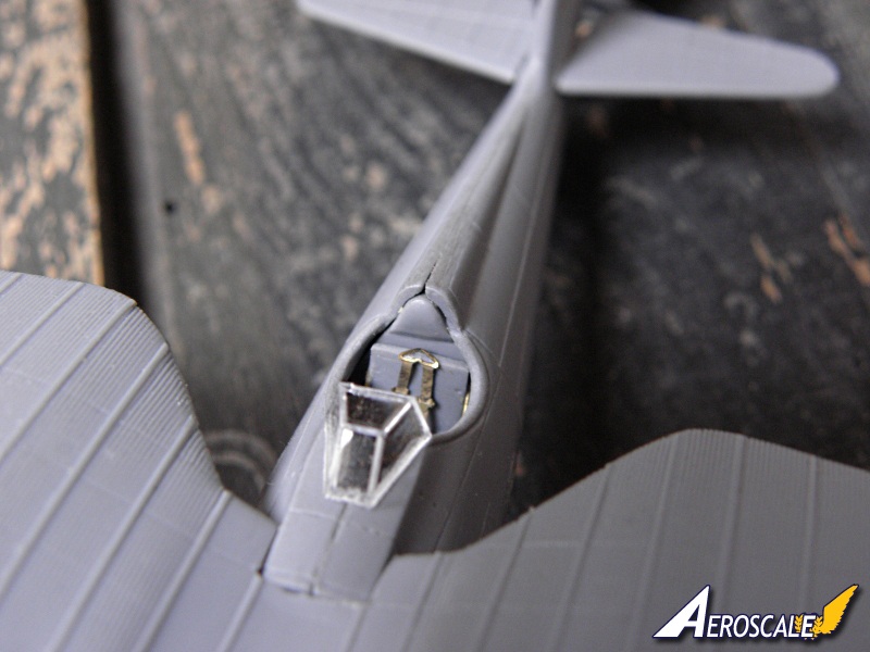
The cockpit interior is rather symbolic. On the fuselage sides producer have reproduced the internal structure of the fuselage and typical furnishing of pilot's seat: control stick, dashboard and rudder pedals. The general impression is enhanced by adding PE details for seatbelts and seat details, throttle lever and rudder pedals. What was a bit disappointment for me as a problematic fit of the instrument panel to fuselage, just below the windscreen. Fuselage have the rounded shape in this place at it results in rather big thickness of the plastic part itself. This characteristic of the kit causes the dashboard fits much lower than it should. First of all it looks incorrect according to the real plane. Secondly it looks simply unsightly. Correction once again won't be difficult but will require some time and for sure you will produce a lot of plastic scobs around your workbench while thinning the fuselage side. In the assembly instruction producers warns and appologies for the bad fit of the frame with bulkhead behind the pilot's seat. It will require additional attention. In my kit the fit of halves was better than expected after reading the warning.
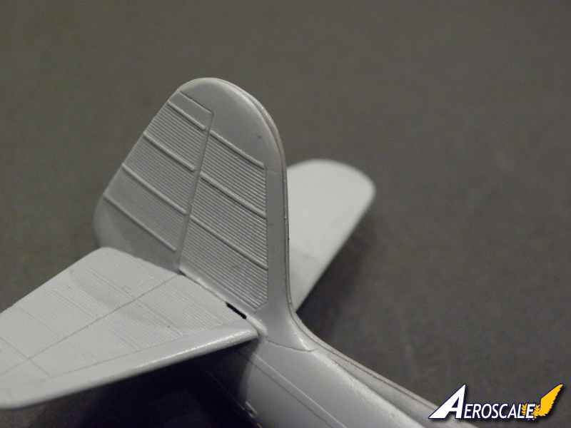
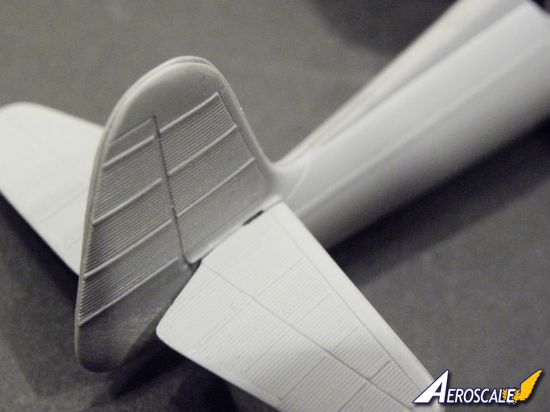
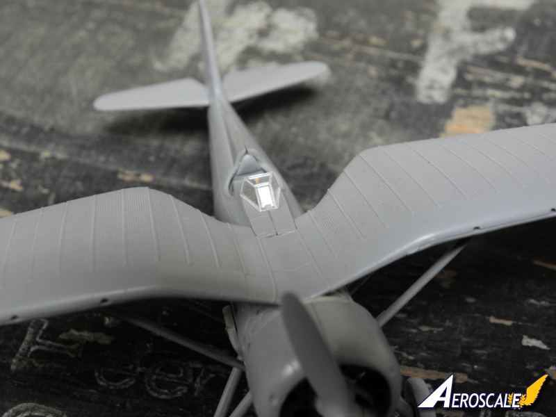
Some time and a bit of grinding will be required, similar to wings, with the rudder trailing edge. If you will have a gap at the joint line a bit of putty and gentle sanding will do the job. What is a big plus is a very good fit of the fuselage and windscreen. As this is a very noticeable detail of the kit you won't have to rework or reshape anything to improve it, of course unless you want to have a perfectly accurate kit.
Engine
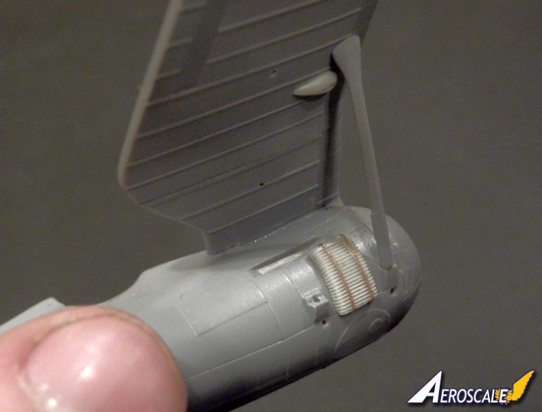
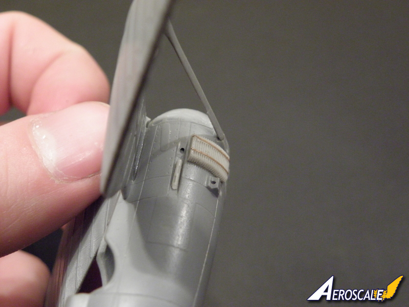
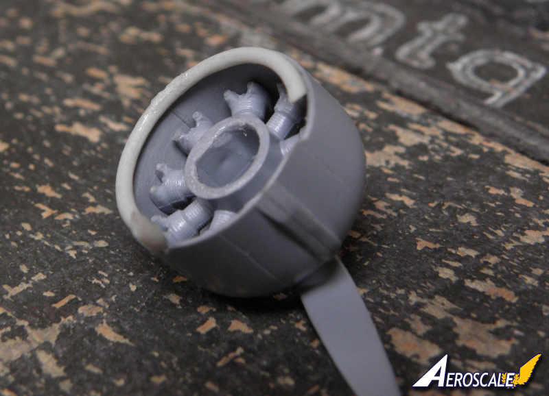
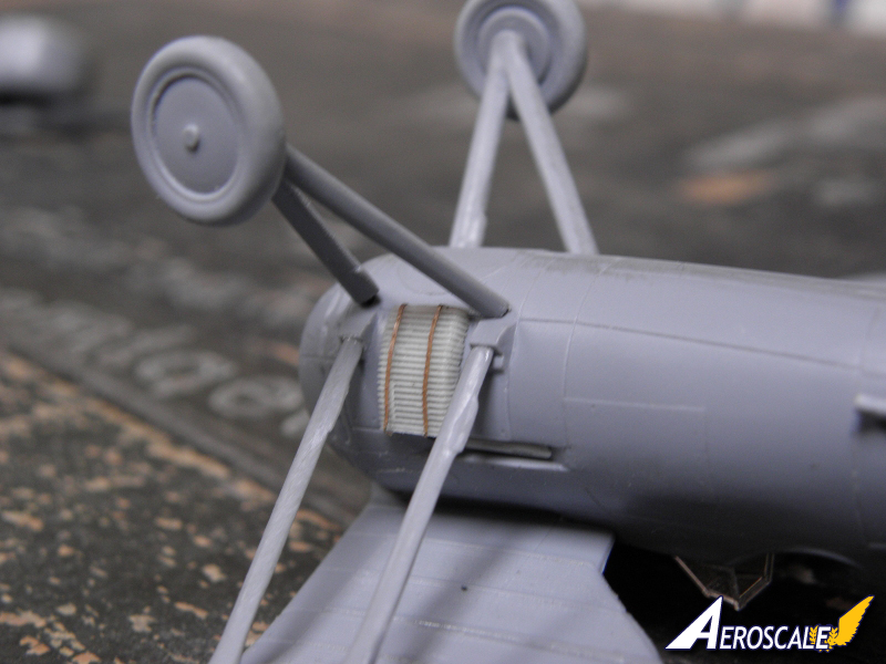
Assembly of the engine unit is quite troublesome. These are just four parts which need to be glued together but it can be quite annoying. Engine itself is made as a single part. Cowling is made of two halves while exhaust manifold is a resin casting. Assembly of these parts, according to the instruction, seems to be rather simple. Glue exhaust to the engine cylinders, add propeller and attach to the fuselage front side, then close the cowling around engine. Et voilà. No, it's not so simple. First of all exhaust seems to be slightly bigger in diameter than the engine and the joint area is limited to the small connectors protruding from the cylinder heads. Combination of these two factors made this step a bit tricky. When it's done and you attach the unit to the plane's fuselage you'll notice that it is hidden very deep in the cowling, so deep that the propeller shaft can't reach the engine. Beside, if you take a look at the references, you will easily notice that the rounded engine reduction is a bit protruding from the cowling. To make the model looking more less like a real P.11f I decided to move the engine inside the cowling to the front and at the same time glue the exhaust to the back edge of the cowling. I hope that attached photo tells the story. This is of course an ridiculous solution from the technical point of view but it makes the impression of correctness. You would have to disassemble the model first to find out what's wrong. If you want to make the kit even more realistic you can add few rods from the stretched styrene for the valves pusher rods, the cowl braces and make the spark plug cables. These details are easy to be scratch build basing on just few photos published in the internet.
Other details
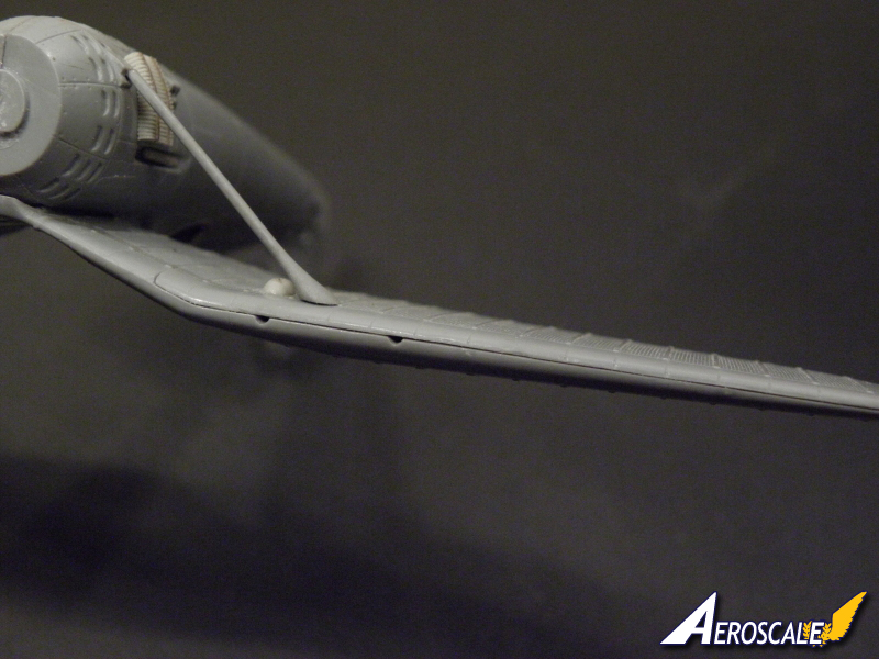
In my opinion the tail wings struts will need replacement or serious reshaping For my taste these parts are way too thick and, if cut to provided length, seems a bit too short. If you decide to use kit parts leave at least 1mm or slightly more as a reserve for further fitting and length adjusting.
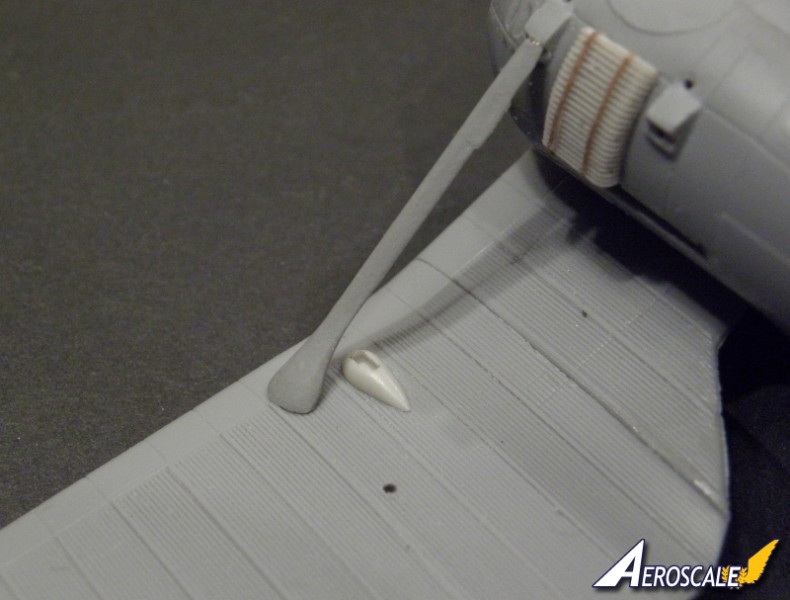
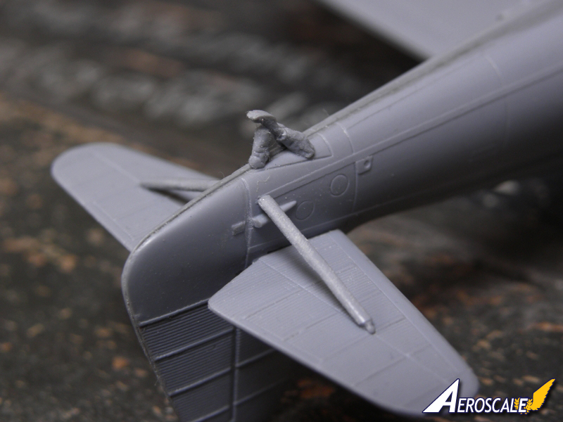
I have to declare here loud and clear that I made few errors during the assembly of my kit. I have glued the struts and tear-drop bulges of ammo chutes in wrong attachment points on the wings. I thought it was ok according to assembly instruction, but unfortunately it wasn't. In this configuration and placement the characteristic Romanian enlarged curved ammo chutes collide with the front struts. Both front struts will have to be moved bit forward while the ammo chutes should be moved a bit back, I say ca. 1-1,5mm back from that characteristic longitudinal panel line between leading edge and corrugated skin. This way we will get the missing space between these parts.
Very good addendum to the kit is a photo-etched fret with smallest details. Gun-sight, antennas or ailerons/rudders pushers, handles and back-mirror do a really good job, adding a good taste of the kit in general.
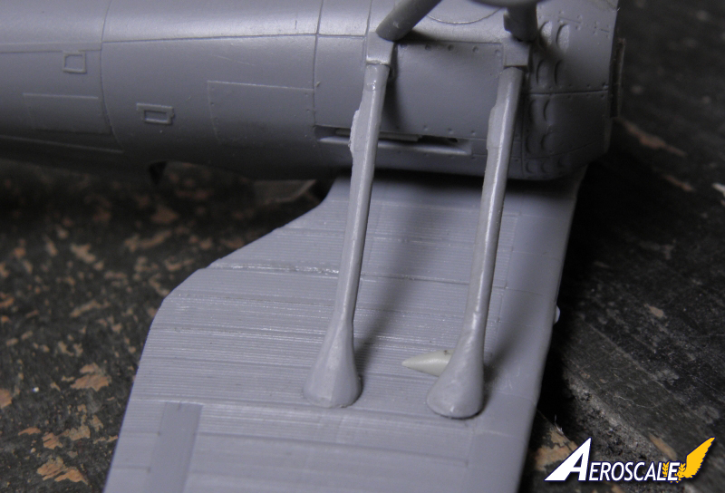
What is not required but will make the modellers life easier is gluing the struts and landing gear to the fuselage on the wire support. Of course you need to pay a lot of attention while drilling holes in thin struts and fairings for the wires but thanks to this small improvement it will be much easier to glue these parts to fuselage. The joint areas are very small and the parts would easily fall away or brake during further handling of the model. I'm almost sure that none of you like to glue again any strut or broken landing gear leg on the painted and almost finished model.
Final conclusions
The general fit of main parts is good and assembly very straightforward. With just few basic tools and some careful fitting you will easily overcome all difficulties. As for the short-run kit there are no flashes and the cleaning of parts from the mould connection lines is limited just to few places. The biggest joint lines were on the main wing struts.
Those of you who are more determined in improving the basic AZUR kit can get an old Polish kit of P.11 and try some surgery of plastic. These kits are easy to get for just 2-3GBP/3-4USD. Smaller details can be also supplied from a very nice Part photo-etched fret, although it was originally designed to other kit. What I also liked almost instantly is the ease of setting the correct geometry of the main and tail wings. I never like to build all these assembly jigs, pyramids and other Eiffel towers for getting the perfect harmony of longitudinal, transverse or perpendicular hypothetical lines of the plane construction. It took me no more than five minutes to glue the wing and tailplane to the fuselage and not get the misshapen shape.
Using an optional resin undercarriage, which for this type are skis, can result in a very uncommon model amongst overs standing on a traditional wheels. There are very good quality archive photographs of the plane in this configuration in the net.
This kit, without doubt, requires experience. Absolute novices in this business or kids may encounter problems too complicated for their skills or patience. If you have at least few finished models on the shelve you don't need to worry as you'll pass all the without bothering about them.
What I like very much in this kit is that it has a high potential for improving and you can stop in any place you want (if for example you're starting to get bored with this kit and just want to finish it as soon as possible) and you will still have a good looking bird. You can improve interior with building the framing around the pilots seat, you can open all the vents around the engine, you can separate the ailerons, rudder and elevator, you can improve and expose the engine or improve the details of the spent ammo chutes.
Whatever you like in this hobby you'll get it with this kit. Scratch building? Go ahead, there are plenty of details you can make yourself. Out-of-box? No problem, you get all you need in one box for a good looking finished model. Your mother always wanted her son to be a surgeon but you failed the exams on the Medical University? Get this kit and an cheap Mastercraft/ZTS/PZW kit and make the home-made transplantation surgery.
Despite its weaknesses or errors for sure this is still the best PZL P.11 kit on the market, for both c or f variants, as the sprues are common for both boxings so I'm very glad and thankful to Azur-Frrom for taking the interest in this topic and releasing the kit.
Please remember, when contacting retailers or manufacturers, to mention that you saw their products highlighted here - on AEROSCALE.
SUMMARY
Highs: Delicate and subtle corrugated metal skin, good fit, straightforward assembly, multi-media inside one box.Lows: Errors in presenting the original construction details, leading and trailing wing edges need a lot of attention and additional time to look good.Verdict: Highly recommended as the best P.11 on the market in this scale.
Our Thanks to Azur-FRROM! This item was provided by them for the purpose of having it reviewed on this KitMaker Network site. If you would like your kit, book, or product reviewed, please contact us.
I have two of these on the go, stalled as I pluck up the courage to install the final fiddly bits and the aerial wires. I also have one of the 11cs partly completed.
I added plastic rod push rods to the engine as they are quite noticeable and help fill the space inside the cowling. The propeller is meant to push fit into the engine like a press stud. This works very well in their PZL P.24 kit, being a tight fit. In these P11s the hole is too small. I stuck a length of plastic rod into the back of the propeller and then drilled through the engine to allow a good length of plastic rod to be inserted.
One reviewer claimed that the exhaust is 3 mm too short. You can see what he means in image 22. I do not think that this is the case. The exhaust fitted like a seal or gasket between the engine cowling and the fuselage. The resin casting is like a spring clip and it can be squeezed into the cowling and then it will fit properly. I did not find it easy to do. I tried to get it to fit half way into the cowling and then tack one end to the cowling with a drop of thick CA glue at the back of the exhaust. Repeat at the other side and then run a bead of CA along the back of the exhaust. It was a bit of a struggle to get the exhaust to sit just the right amount inside the cowling. Next time, and there will be a next time, I'll try using some Blue-Tac to stop it going too far.
The exhaust outlet should end in the joint between the wing strut and undercarriage leg. I don't think this is possible on the kit however you fit the exhaust because the leading edge of the wing it the limit to how far back it will go. Looking at photographs it seems that the exhaust was not a curved pipe of constant circular cross-section but widened and flattened as it went around the port side.
The kit is basically the earlier P.24 with a new fuselage. This means the wings a not quite the same as those on the P.11. The P.24 could have two guns in the wings but the P.11 only one so there are extra panels line that cannot be filled because of the corrugations.
The outer hole in the leading edge needs to be filled. The instruction sheet places the blisters in the wrong place (the outer guns) but in the the correct position on the camouflage and markings drawings. Also on the box art. The blisters are handed, i.e., mirror images. This will give Gaston Marty an attack of the vapours as they should be identical.
There was no left and right machine gun so the cartridge exited from the same side. This does not matter on the p.11f as the blisters are covered over by the chutes.
I prefer to use Microstrip for aileron trim tabs as I find the PE ones stick to masking tape better than the model and are easily removed when it comes to painting time. I also replaced the rudder trim tab with Microstrip. (The P.24 fuselage does not have a rudder trim tab , it being on the PE set. The P.11 PE set also has the rudder trim tab.)
The fuselage is the shape of P.11 but the cockpit, apart from the instrument panel, appears to be the same as the P.24. They failed to replace the rear bulkhead with one for the P.11 as the instructions tell you to Grind the shape of the fuselage bulkhead (part B10) to fit smoothly prior to mating the fuselage halves. Unfortunately this part was substituted during the mould preparation.
I have a better way of dealing with it. There was no bulkhead on the real thing and it does not have much of a useful function in the model. So I cut the headrest off and filed it down to fit and stuck it in position. The seat, when installed, covers the hole behind it completely. Thus an evenings filing and cursing is avoided.
The strap that secures the jettisonable fuel tank is not well moulded. I scraped it off and replaced it with a piece of a spare seat belt. Opportunity missed as I would rather have this included in the PE set instead of those tiny bits that everybody is frightened to use.
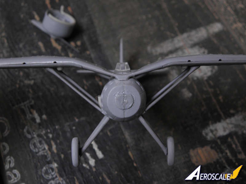
For the undercarriage I made a template from card using plans to set the right angle. I placed a drop of Bob Smith's finest thick CA on the attachment place on the fuselage, placed the leg at the correct angle and then applied a drop of kicker to set it instantly. This was done using my 'Dalek' method, that is, holding a brush between my teeth soaked with kicker. After the legs have set I added a little more CA to fill in the gaps. This has produced a surprising strong joint and I have not had any problems with the legs breaking off. There is a pimple where the wheel fits but no dimple on the back of the wheel for it to fit into. Therefore it is necessary to file away the pimple so the wheels can be glued on. Best to do this before attaching the legs. As the supporting struts were flat in section I used Microstrip for these instead of wire.
The resin skis are nicely cast but care is needed with the attachment brackets which are rather delicate and require a lot of flash to be cut out of the gaps. Fitting them is a little bit awkward as it is difficult to get them aligned so the aircraft sits perfectly. In the end I used one of those jigs for building biplanes to suspend the model at the correct height and then glued the skis to the legs. The instructions do not show exactly where the supporting cables are attached to the skis. You need to consult photographs to find out. Photographs show that this aircraft was not fitted with machine guns, wings and fuselage, or antenna wires.
Decals are excellent and respond to setting solutions which are necessary to get them to settle down properly in the corrugations. The five options have all been taken from the MMP book Rumanian Fighter Colours 1941 1945. On the instruction sheet aircraft 79 and 122 (the one with skis) are shown with rudder stripes. On the colour profiles on the back of the box they have no rudder stripes. Photographs show that they had no rudder stripes so follow the box not the instruction sheet.
Colours are only given as Gunze, not exactly easily obtainable for many. According to the book the colours were RLM 64/83 and RLM 65 possibly 76. Throughout the text the underside colour is described as light grey so I went for RLM 76 as that is a blue-grey colour. I used White Ensign Models RLM 83 and RLM 76. The yellow used on the decals is much lighter than that usually used (RLM 4). I found Humbrol 99 Lemon to be a good match.


Comments