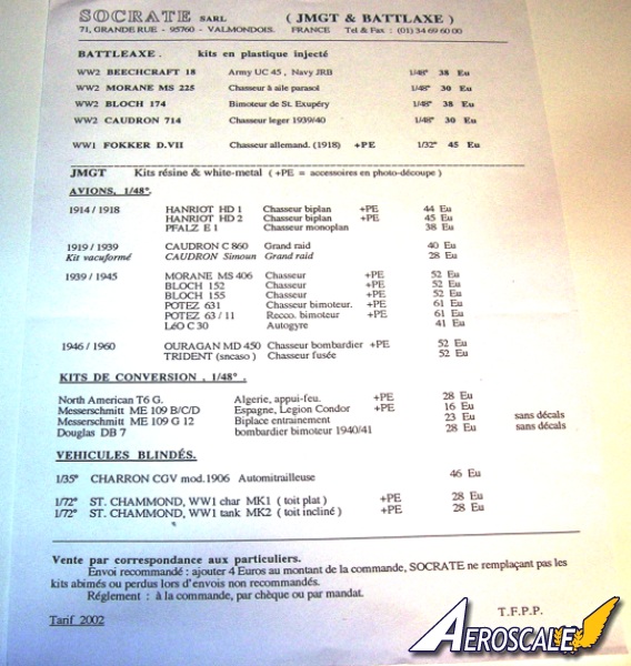
The Fokker D.VII became Germanys main production fighter in 1918. Usually it was matched with the Mercedes D.IIIaü 180hp engine. It was the variant with the BMW IIIa 185hp motor that pilots prized ultimately. With few idiosyncrasies it was not temperamental and a novice with a little nerve could do well. The contemporary construction using welded metaltubing for the fuselage and wooden wing structures was typical. The secret appeared to be in the cantilever boxed wing spars and the simple design eliminated the need for multiple exposed rigging wires. For several reasons the Fokker D.VII is a must have item in the serious collector / modelers stable. The lack of rigging is a big plus, the various decal sheets of Lozenge patterns, unit and pilot markings that are available in most scales. Books on the subject are also at an all time high.
Kit History
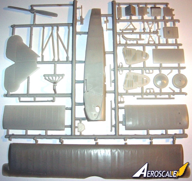
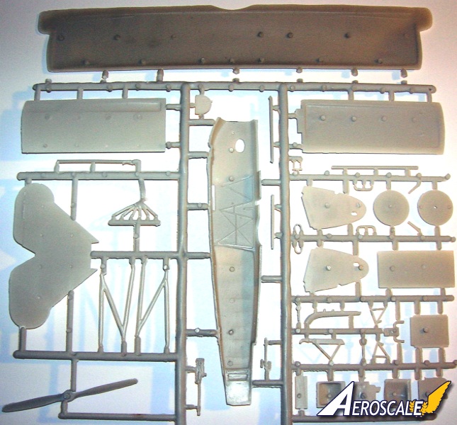
This large scale kit arrived from Battle Axe in about Nov. 2001. Typically this is a short run mold with and I expected moderate amount of clean up of all the parts needed after removing from tree. This entails surface pits or pebbles as rough areas that are easily dealt with. As this was Battle Axes first run at 1/32 scale slush moulding it is a good first effort in my opinion. I would place it in the same category as Eduards first efforts. The mold design is semi-typical for large scale kits. Horizontally split wings and atypically split elevator / stabilizer units. The fuselage is vertically split in halves. The retail price has this Fokker D.VII going for $49.95-$59.95 USD.
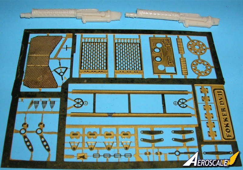
Kit contents
76 plastic parts
02 resin parts
46 white metal parts
02 decal profiles
Interior
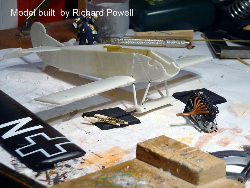
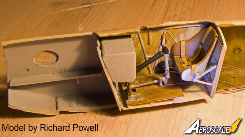
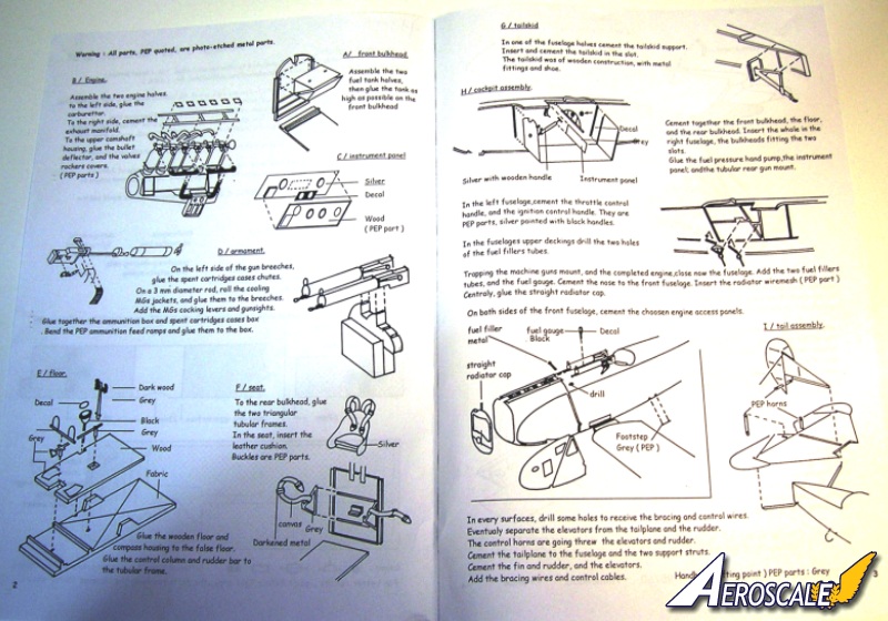
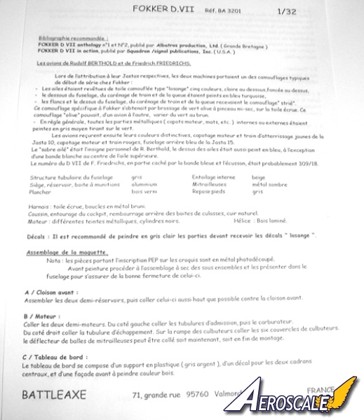
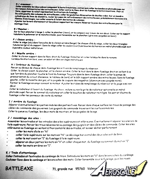
First, drill all rigging pilot holes. Since I intended on displaying the engine, I removed the inset attachment walls for the nose cowlings panels on the forward area of the fuselage halves. I erased and replaced the molded cockpit structure in the fuselage halves with painted brass rod sections. Note that the factory printed lozenge pattern fabric used on the Fokker D.VII showed through the interior of the cockpit sides in reverse in lighter shades. The earlier streaked type of Fokker camouflage did not penetrate the fabric in the same way the printed lozenge type did. Simply an off white will suffice here. I will usually paint Fokker company instrument panels black and all others give a varnished wood look. The two fuel gauges on the instrument panel are recognizable items. Add a hand crank type handle to magneto, also flip levers to fuel and air controls open also add a new tachometer dial to the machine gun rear brace. Dont use the other openings for gauges. The furthest right circular opening should house the water pump greaser. The furthest left circular opening has a small flip lever. The plastic instrument panel fits these into their openings of the brass facade. At the rear of the fuselage underside cut open an aperture for the tail skid mounting in the rear portion of the fuselage halves.
The seat and its supports are out of scale thickness. You can trim down the inside surfaces of the seat and replace the supports with bent brass rod. I chose the Toms Modelworks items from the 1/32 scale German interior brass set. The seat was covered in fabric that was held by attaching it to eyelets in the seats outer rim. As parachutes came into use the seat was made deeper to accommodate the chute pack as a cushion. In the cockpit rear bulkhead /screen pre-drill holes for rudder control cables to be added later. This item will have to be considerable sized down around its perimeter to fit well, so I scratch built this item. Whatever the fuselage covering, use the same covering on the rear cockpit screen. In the case of streaked camouflage I go with plain off white. For the rest I would normally choose 4 or 5 colour lozenge. I believe Squadron or Rosemont Mail Order usually has individual sheets available, in case you want one entirely in lozenge.
The rudder control assembly needs to have the rudder bar attached to a scratchbuilt column that runs from the ammo box to the control columns horizontal axis at its forward end and then the cable attachment rings are added to the rudder bar. Set the rudder control assembly and control column to the desired position to compliment the attitude you have chosen for the ailerons, elevators and rudder. The lap and shoulder harness need to be scratchbuilt as only the harness buckles are provided. Again I turned to the Toms Modelworks German interior set and drape the ends over the seat or have them hang out over the cockpit rim after assembly of fuselage halves. Scratch build an aileron control V for cables and attach the V at the front end of control and cockpit floor assembly.
Before uniting the fuselage halves add rigging material to the rudder bar and control column through pre-drilled holes in cockpit rear bulkhead as discussed previously. Also you should add the compass and a fuel pressure hand pump to the lower side of the cockpit on fuselage half. I find that Toms Modelworks brass interior sets are great. They often provide just the right pieces to complete the job. Unite your fuselage halves now and begin working on the engine compartment. Check the sit of the engine, making sure that it lines up well with the shaft opening in the nose of the fuselage. The kit recommended method of installation has the rear peg inserted into the firewall and the lower peg into the bottom of the fuselage. I strongly recommend some earnest scratchbuilding to represent a metal tube structure. Check your references.
Engine
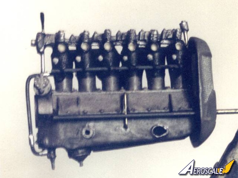
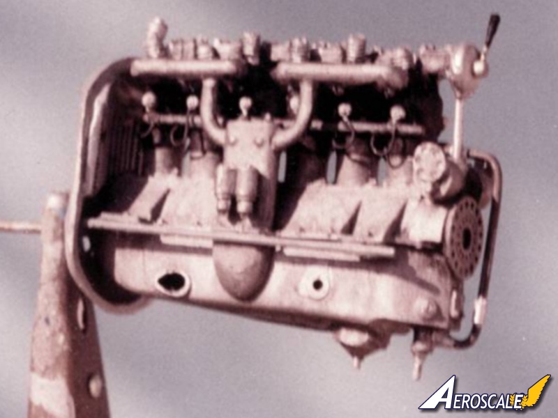
The kit Mercedes D.IIIaü inline motor has soft detail representation. Check the listed references provided for some keynote differences. The cylinder jackets themselves were the color of blued metal The BMW IIIa is needed to do some variations. Truthfully, most people wont know the difference. The BMW IIIa sat higher in the compartment so about 1.5" more of the cylinders could be seen than with the 180hp Mercedes D.IIIaü. The air induction pipes were unified where the Mercedes was divided.
The immediate visual difference in the early Mercedes 160 hp D.III / 170 hp D.IIIa and its progeny the 180hp D.IIIaü is the rocker springs exposed above the cylinder jacket heads. On the early D.III 160hp and 170hp D.IIIa the rocker springs are centered on the sides of the rocker box covers. On the D.IIIaü 180hp the springs are located on the forward leading edge of the same covers. They were also that way on the BMW IIIa 185hp. The rest is below the cowling and not readily visible if left closed. In 1:32 several good manufacturers note the difference and have two distinct castings for the Mercedes 160hp and the 180 hp. The Mercedes D.III 160hp was outclassed by early 1917. The Mercedes D.IIIaü 180hp was the standard engine in both of the Albatros D.Va starting in late 1917 and then the Fokker D.VII through 1918.
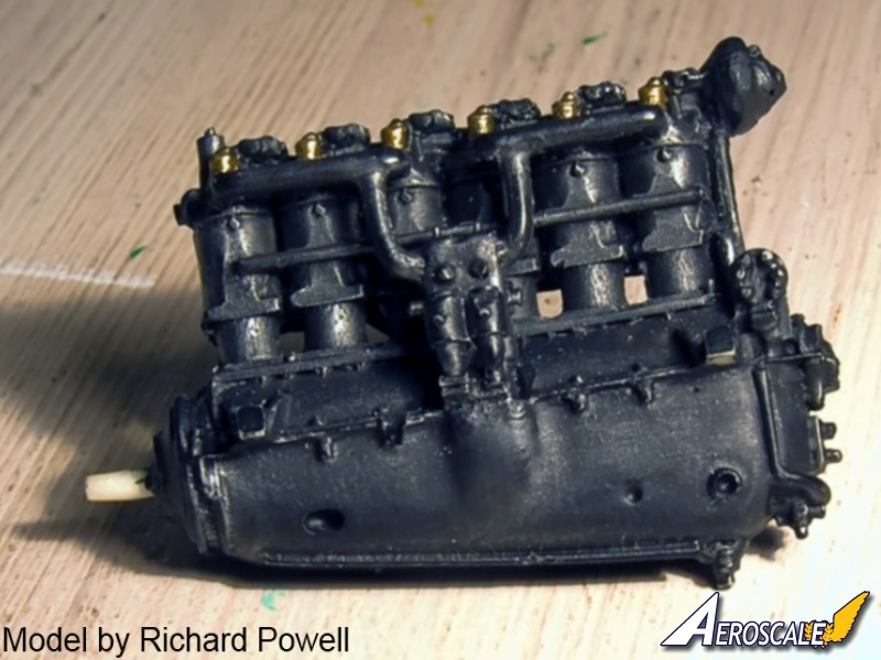
I decided to try my hand at altering Toms Modelwork Mercedes D.III 160hp to the 180hp D.IIIaü version. This entailed separating the rocker boxes and camshaft from the upper heads of the cylinders and moving the whole assembly back approximately 1:8 of an inch. The water pump was separated from the twin magnetos and a simple shaft replaced the pump. The oil pump was removed and relocated further forward and a water pump was scratchbuilt in where the oil pump had been. Breather ports in the oil pan were drilled out. Rocker springs were removed and replaced with rotary engine cylinders taken from two 1:72 scale Revell Fokker Dr.I kits. Rocker arms were scratchbuilt from small diameter shaped brass rod. I added a scratchbuilt an air pump to the front of the motor and a decompression handle to the rear of the camshaft housing (joining the simple tower and the camshaft.) Holes drilled for the spark-plugs and GrandtLine nuts inserted to resemble the plugs. Around the shaft of the twelve new spark-plugs I wrapped small sections of brass wire. These were joined to another section of rod spanning across the cylinders to simulate the spark-plug wire conduit. Small sections of wire were then cut and fitted to the magnetos and the rear of these wire conduits. These spark-plug wires were then painted a flat slate grey colour. The Spark-plug connectors themselves were painted white. Finally the various external plumbing sections were added using various diameter brass rod sections cut and fitted into pre-drilled holes. Painted with Metalizer paints and grimed up a bit I added the two engine support tubes (one to each side by the motor mount flanges.) These support tubes extended into the back of the kit radiator shell into pre-drilled holes. Careful test fitting of the engine/radiator assembly gave me a tight but good fit of the unit into the engine compartment for permanent attachment. Some sanding will need to be exercised on the radiator shell to get a better fit. I covered the radiator face with painted Detail Masters nylon micro-mesh screen. The remaining cockpit structure can be added using cut and painted sections of brass rod. Check your references.
Machine Guns & details
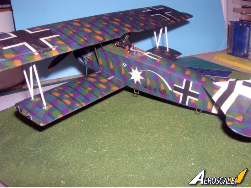
The cowling side panels are crucial in determining the parentage of your D.VII. The instructions lead you to use the early panels with the lesser amount of louvers/vents. The multi- louvered/ vented panels are for later production schemes. Fokker D.VII chosen profiles are early production types from the parent factory at Schwerin/ Gorries Germany. Technical indications lead us to believe that these represent machines from production batch 230/18- 376/18. I didnt like the gutters used to depict the access panel edges on these cowling panels, so I scratch built these out of thin plastic stock. The fretted gun jackets can be annealed over a wooden dowel. I also replaced the empty belt chutes with bent and blackened brass-rod. The machine gun jacket ends should be opened slightly with a motor tool so it will seat completely on the plastic gun barrels and jacket openings. This is a delicate process so work deliberately and carefully. A set of resin Spandau guns are included in the kit as well. The completed Spandau machine guns should be painted in semi gloss black as all of the outer surfaces were covered in baked on black enamel on the original. Highlighting in a gun metal colouring maybe appropriate here. The pilots left ammo feed needs to be removed and relocated as it sits where the left gun should sit.
Tail surfaces
The horizontal tail unit is in two halves and can be approached in several ways. You can either sand half of both pieces away to get the right thickness or simply glue a .020 thou plastic stock sheet plastic to the bottom side of the upper piece. Detail by adding rib caps from either heat stretched sprue or Plastruct strip stock. Cut the division for stabilizer and elevators, preferably before attachment to kit piece.
Wings
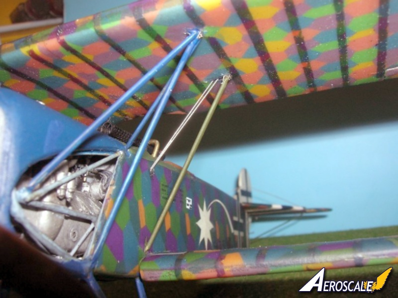
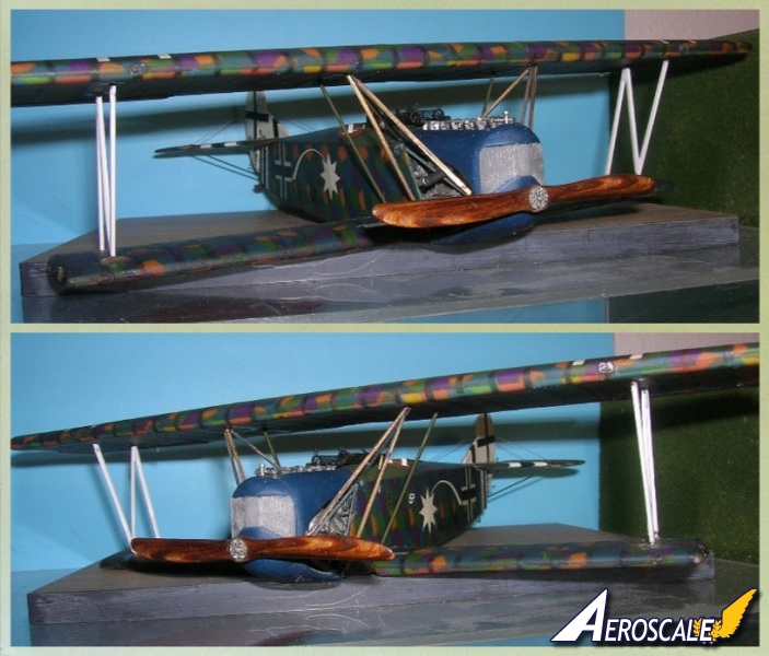
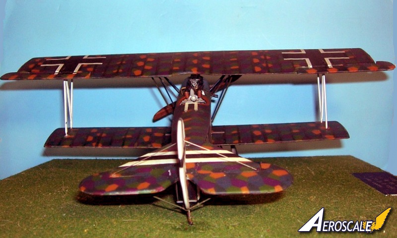
The top and lower wings can be built straight because of the method of casting the mold. Each wing is cast in two pieces (upper & lower) a rigid spar can be built up from wood or plastic. I was successful without adding a spar. The ailerons are shown attached to the wing surfaces. Their hinges lines are mismatched by about 1.5mm. I suggest filling the separation line on the undersurface then re-scribing to match the upper surface. Now by this time I have painted and decaled all surfaces and they are thoroughly dry. Now concerning the cabane and interplane struts, the kit items are a little thick. With careful work they can be brought down to a scale thickness but you will lose a lot of rigidity and strength, In the end its better to go with scratchbuilt brass items. You can begin with brass rod stock or purchase a set of Strutz (the name for Aeroclubs is oval cross sectioned brass.) Check your references and compare the wing gap using dividers or even a inexpensive school compass. To bring the assembly together I use childrens Lego blocks to form a jig to keep everything level and square. Then add scratchbuild the cabane struts. Adding the half moon strut attachment flanges with GrandtLine nut heads to the underside of the top wing to the cabane struts is a nice touch to add as well.
Landing Gear and Propeller
Erase the union seams on the axle airfoil. I replaced the under carriage legs with cut and shaped brass rod.. Replace the stabilizer struts with painted brass rod. Check the attitude of the step and grab handles. This also seems to be a factor to some extent of determining parentage. (That is, each factory had its specific hallmarks or signatures of their productions.) I built these out of brass as well. I attached the aileron control horns. The kit propeller has the wrong pitch on one blade for a 180 hp - 185 hp engine. I decided to try one of Martin Digmayers fine versions of the Heine propeller from Copper State Models. Mr. Digmayer is a master and known for his correct shape and colour laminations. This is the fifth prop Ive purchased from him. I usually do my own and replace the kit parts with items that I scratch build by laminating layers of light and dark woods and sanding to shape. The process is rather easy and gets easier with each attempt. My usual venue is 1/48 scale and thats what my blanks (laminated sections of light & dark woods) are set up for. As this build is in 1/32 it just made it easier to order it ready built. The kits prop bosses are both a little large for scale correct propeller. So I used the ones from Toms Modelworks German detail set that I purchased for this build. They are dead on. You could also scratchbuild an anemometer { an air speed indicator) and add it to the N struts if your chosen profile has one. Use the Revell 1/28 Fokker D.VII item as a pattern and simply scale it down.
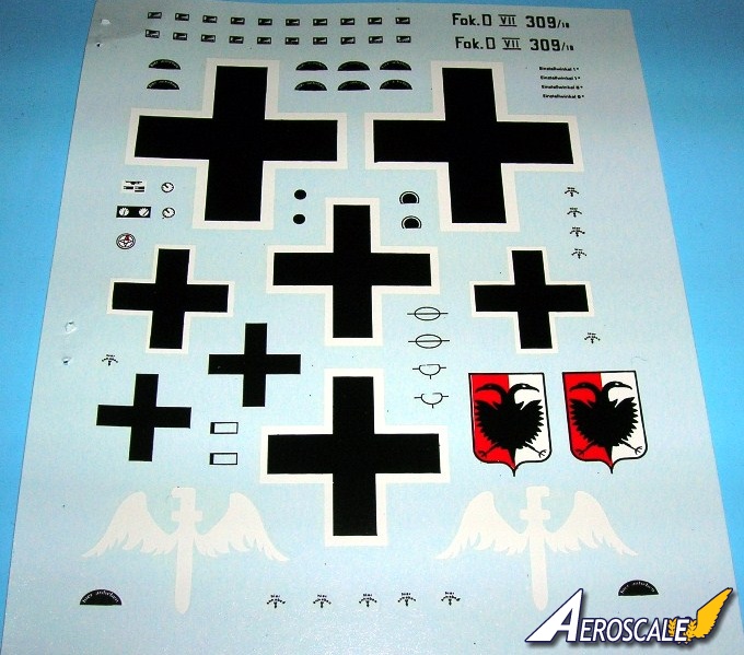
Kit Decals
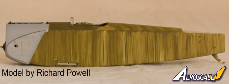
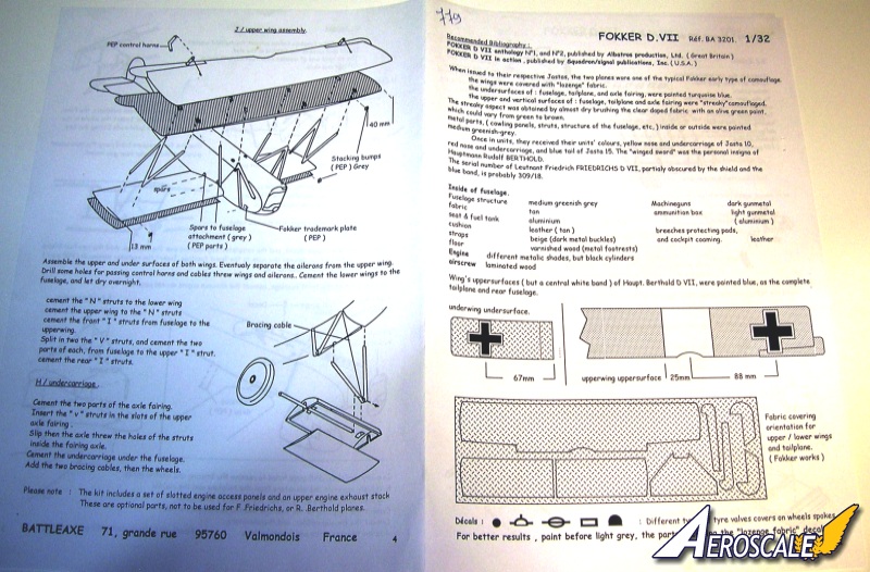
Again technical indications lead us to believe that these were from production batch 230/18-376/18. Check listed references. I found out too late that the lozenge decals are translucent. You may want to first paint the upper surfaces of the plastic a dark to medium green and then clear glossed. This tends to subdue the decal colors and bring them a little closer to the original fabric colours when you apply the upper surface lozenge decals. Painting the lower surfaces lt. grey is fine if you just lay down a clear gloss coat first. If you intend on using the lozenge decal cut in strips for the rib caps you should give the uncut decal a generous coating of clear gloss. To completely cover my model rib caps and all, I had to have a total of three sets ( six half sheets) of the upper camouflage coloured decal sheets for my build.
1. The kit identity of D.309/18 is actually D.258/18 assigned to Ltn. Friedrich Friedrichs of Jasta 10 in early 1918 is generally accurate.
2. Serial unknown assigned to JG II Commander Oblt. Rudolph Berthold is generally accurate.
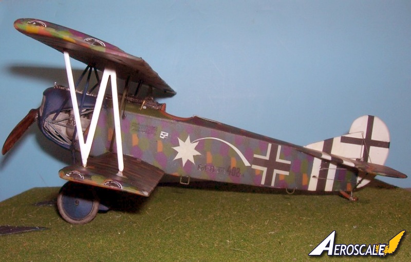
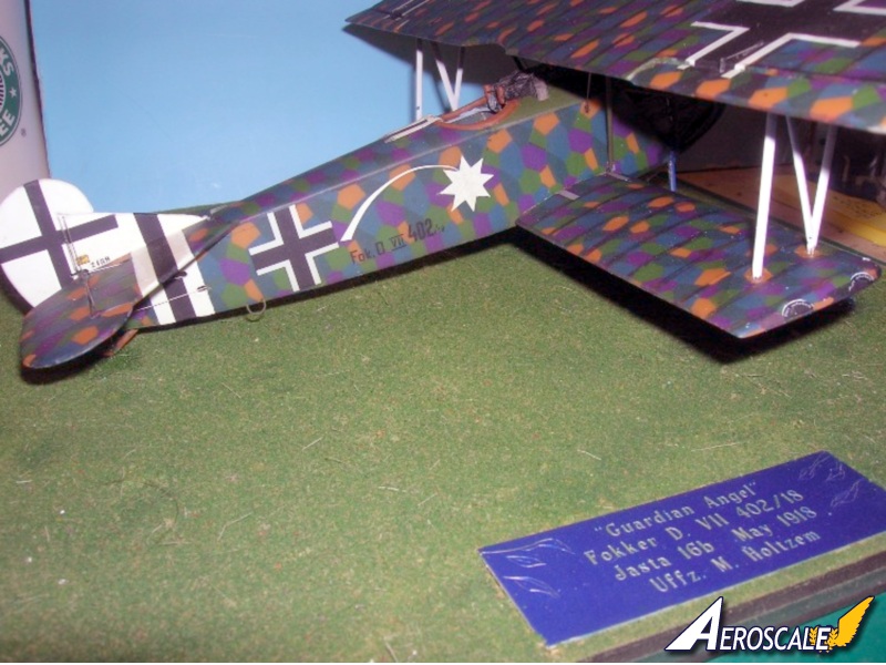
My build representsFokker D.VII 402/18 assigned to Vizefeldwebel (acting Sargent ) Max Holtzem of Jasta 16b. Vzfw. Holtzem had been assigned to this unit on 22 Sept. 1917 and stayed there until the end of the war. A modest man he refused to take credit for any of the combat victories that he took part in. Around the turn of the century the comet was seen as a departed soul en route to heaven. Holtzems mother had died when he was nine years old and he had the comet painted on all his Jasta 16b aircraft to denote her spirit as his Guardian Angel. Holtzems own description says that this machine was his at the wars end. He says that he acquired some benzine and flew the machine home where he hid it. His narrative goes on to say that he removed the guns and later added a second seat behind the cockpit. As an aside I would like to note that Max Holtzem immigrated to the USA after WWI and settled in Whittier Beach California. During WWII he worked as a quality control inspector on the P-51 Mustang assembly line. Max Holtzem later befriended Dr. J. J. Parks President of the Lafayette Foundation and shared his wartime experiences. Two years before his death in 1980 Max posed with the foundations replica Fokker D. VII in one of our German officer uniforms as evidenced by the photos presented here.
My Building Costs
1. Battle Axe Fokker D.VII (msrp) 49.99 - 59.99 USD.(I purchased mine for 25.00 USD.)
2. Toms Modelworks German Interior set #502. = 1 @ 6.75 USD
3. Toms Modelworks German Machine gun set #500 = 1 @ 6.75 USD
4. Copper State Models Spandau Machine Gun set #125= 1 @ 5.99 USD
5. Toms Modelworks Mercedes inline 6 cyl. 160hp = 1 @ 7.00 USD
6. Battle Axe Lozenge Camouflage = 7.96 @ (two used). 15.92 USD
Total 67.41 USD
Final comments
As mentioned earlier I expected a moderate amount of clean up and in that I was not disappointed. In fact the build itself was labor intensive. While not a bad thing I realize it was upto me to decide just how much work to put into it. Another unique aspect was the translucent Lozenge and its light absorption rate in differing conditions or time of day. Normally I would have attributed this to the variance in the film developing. What I noticed as I progressed was that I saw a definite visual change that was reflected by these conditions. I suspect that after having been clear varnished at the factory the full scale aircraft would possibly undergo a similar visual changes in various lighting conditions.
References
Combat Colours #14 The Fokker D.VII by P. Cooksley, Airfix Magazine. Date unknown.
Details & Colours Windsock Intl. Vol.3 #3, Summer 1987.
Fliegertruppen #2 by A.Ferko, Privately Published, Salem Ohio, 1987. (photocopies may be obtained by contacting the University of Texas at Dallas through the special aviation collection.)
Flight Report Cross & Cockade Great Britain, Vol. 2 # 4.
Fokker D. VII Aces of WWI, pt. I by Franks & Van Wyngarden. Osprey pub. 2003.
Fokker D. VII Aces of WWI, pt. II by Franks & Van Wyngarden. Osprey pub. 2004.
Fokker D.VII by Egon Kreuger, Profile Pub. Ltd. 1962.
Fokker D.VII by P. Grosz, Albatros Pub. Ltd, Datafile #9. 1989, 1993, & 1994.
Fokker D.VII Anthology 1 by R.Rimell, Albatros Pub. Ltd. 1997.
Fokker D.VII Anthology 2 by R.Rimell, Albatros Pub. Ltd. 2000.
Fokker D.VII Anthology 3 by R.Rimell, Albatros Pub. Ltd. 2002.
Fokker D.VII Kit Survey by R.Rimell, Albatros Ltd. Windsock Vol 13, #4 1997.
Fokker D.VII Covering Practices by Dan-San Abbott, WWI Aero #102, Pp.22-33. 1984.
Fokker D.VII Detail Marking and Finish of Fokker-built D.VII Aircraft by Dan San Abbott, WWI Aero #107, 1985.
Fokker Fighters of WWI by A. Imrie, Osprey, Vintage Warbirds #6 Pp.41-64 1986..
Fokkers Last Deadly Scourge by M. OLeary, Air Combat, Pp. 18-26. 1975.
Forgotten Fokker by P Cooksley, Cross & Cockade GB Vol.4, #2,,Pp.84-86. 1973.
That Fokkers an Albatros! By Wally Tripp, WWI Aero, #102, Pp.14-21. 1984.
Udets Fokker D.VII Fighters by Dan-San Abbott, Windsock Vol.4, Spring 1989.
German Army Air Service in WWI by R.Rimell, Osprey, Vintage Warbirds #2, Photos 42-44, 1985
Germanys Last Knight of the Air by C. Degelow, William Kimber Pub. London, 1979.
Wings of War by R. Stark, Arms & Armour Press. 1973.
When contacting retailers or manufacturers, please remember to mention that you saw their products highlighted in review here on Aeroscale.
Highs: Unique subject matter for its day. kit is complete in part for the build.Lows: Mismatched aileron leading edges in the top wing. Severely undersized internal parts like the engine. Crude and overly thick parts. Lozenge decals are more like vinyl. Verdict: Slush type moulding did much to give this kit a disadvantage. Still it can be built.
About Stephen T. Lawson (JackFlash) FROM: COLORADO, UNITED STATES
I was building Off topic jet age kits at the age of 7. I remember building my first WWI kit way back in 1964-5 at the age of 8-9. Hundreds of 1/72 scale Revell and Airfix kits later my eyes started to change and I wanted to do more detail. With the advent of DML / Dragon and Eduard I sold off my ...
Nice story about Max Holtzem, Stephen I do remember seeing your build of this over at wwi-models. I was, and still is, very impressed with your efforts on a hugely difficult kit. I built it myself but I don't like to talk about it, the memory is still painful...
Mikael


Comments