

1⁄35Focke-Wulf Fw 190 D-9 - Part 3
...
Post a Comment
DID YOU MAKE THE CONNECTION?
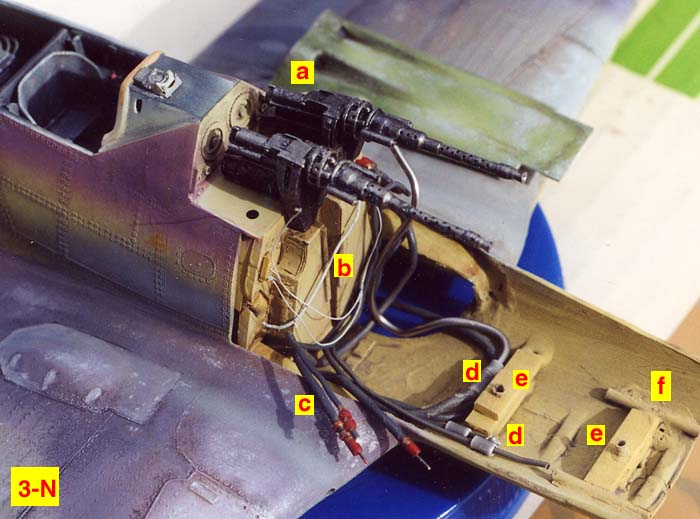
See Photo 3-N and understand that we're gettin' curious-er and curious-er! It's another example of that same "theme" from above, repeated once again. I needed to devise a way to connect all the solder hoses to the engine connections and come up with an idea that would allow for the other hoses and wires to be visable when looking up through the wheel well opening below. Now, Bill Pettyjohn, a master aircraft modeler, and my good friend I mentioned earlier, has the skill to get every part of a real aircraft engine compartment into his model. I don't have that kind of talent. So with me, it is a question of abstraction. My meaning is that I hoped to put enough of the elements in scale, that you would see in the real aircraft engine compartment, in my model, to give you the "idea" that it was all there. But in truth I've only scratchbuilt a portion of all the parts from the real aircraft. I was after the "look" that would create the "illusion of reality" rather than getting each and every part in the model from the original twelve inches equals a foot scale aircraft. So at letter "a" you see the MG 131 resin machine guns temporarily in place using brass "pins" in the bottom of their bases that fit into drilled holes in the PE metal platform. You'll also notice that I painted the machine guns black and drybrushed Testors steel over the black. That was the period before I realized that black was too dark a color for scale, IMO. If I were painting those machine guns now, I would substitute the black paint with dark gray paint. A minor distinction, but one that I now consider important. Letter "b" shows some of the coated copper wire glued in place and painted off white. Letter "c" locates one of the .062 diameter solder wires I used for connecting hoses. More about that when you look at Photo 3-R which shows the rather crude colored pencil sketch I drew, in an attempt to more clearly explain the basic aspect of connecting those solder wire "hoses" to the engine. Letter "d" (shown in to places) indicates the where I had previously glued in a short length of gray styrene tubing. Here and in certain other cases, I used that gray tubing as an "anchor" to hold in place pieces of solder wire or "hose" that would be bent and curved into position under the engine and above the wheel wells. It was easy to slide the solder hoses in and out of those "anchors" in case I determined it was necessary to shorten the length of the solder hoses, or replace them all together. The Squadron Signal Walk Around book very clearly showed that the connecting hoses were visable from looking up through the wheel wells on the real aircraft.But at the point this photo was taken, each solder wire hose was removable, not glued in place.You see letter "e" in two places. They indicate the location of the two pieces of plastic tubing, where the pins in the bottom of the kit engine fitted down into. These pins were mentioned earlier. Letter "f" shows the location of a length of brass tubing (its been painted over and unfortunately is almost cropped out of the picture) that was super glued in place there and in the same spot on the starboard side in the bottom of the forward part of the engine compartment. The old Hasegawa engine cowl ring (shown in photo 3-J) had brass pins glued in the bottom, previously, so I could insert those pins into the brass tubing parts (letter "f") to hold the engine cowl ring in place while I was dryfitting, dryfitting, dryfitting. Of course, in the final phase, those inserted brass pins were super glued into position once all the fit problems were taken care of and all of the scratchbuilt pieces were glued in place.
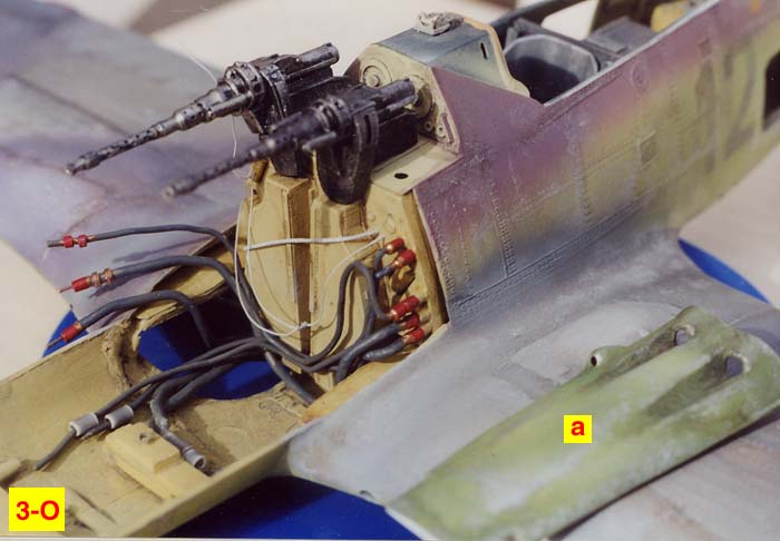
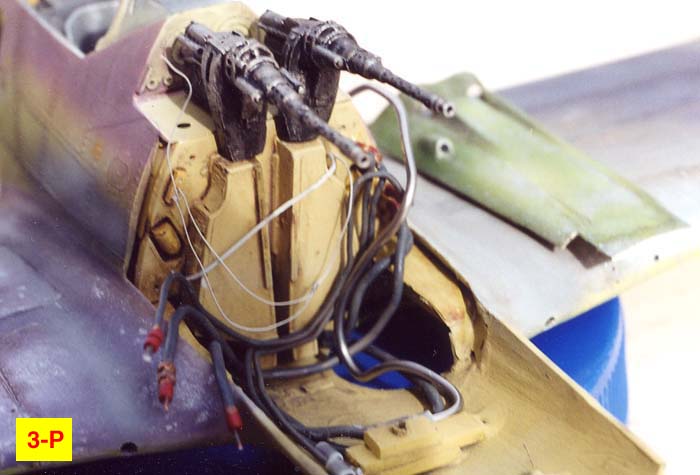
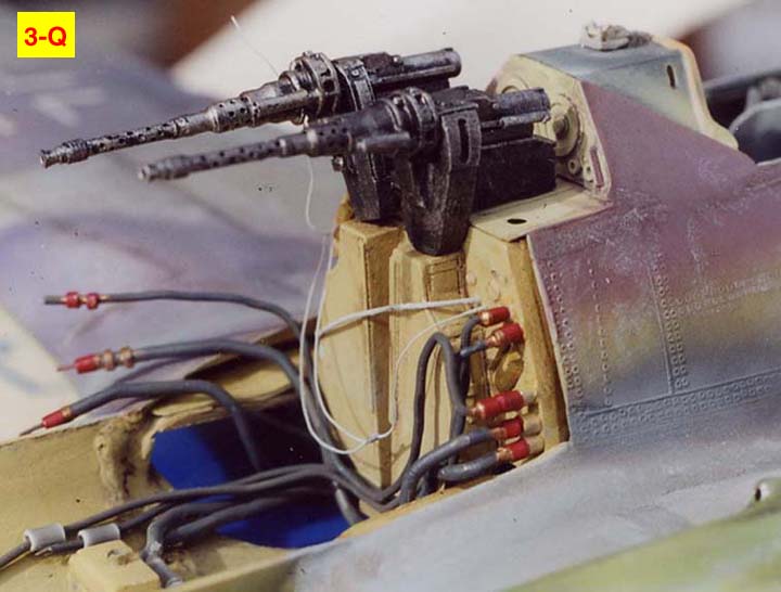
Photo 3-O shows another view of the same area shown previously in Photo 3-N. Letter "a" in this photo indicates the completed, painted vacuformed piece, the top engine cowling that would be glued in stationary position above the engine, . . . much later. The twin MG 131 gun barrels had to fit into those cowling openings. Photo 3-P and 3-Q are yet two more views of the same area. From these photos, you get a much better idea of how those twin machine guns had to fit down on top of the resin MG magazines attached to the firewall. Now remember, when a judge or another person would view this area, most of it was covered over by the exterior panels, the raised engine cowlings. So they wouldn't be able to see everything in such detail. And to me, as a contest entrant, . . . that was a good thing.
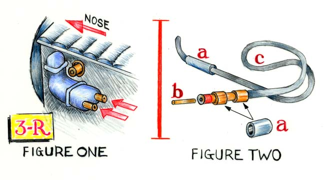
Photo 3-R shows that rather crude colored pencil sketch I quickly drew, that was mentioned above. But hopefully, it will help to make thing more clear in reference to the .062 solder wire "hoses" and how I connected them to various crucial areas in the firewall and into the engine hose connectors. Figure One shows how I drilled holes in the kit engine. The two red arrows point to the engine hose connectors which the brass pins in the end of the solder hoses, will slide into. These connectors were actually gray styrene rod. I then drilled holes into those styrene rods the diameter that would receive the brass pins that are shown in Figure Two at letter "b". The Figure One sketch isn't exactly correct as there was only one engine hose connector location on the engine's port side. But there were three connector locations on the starboard side of the engine. In Figure Two at letter "a" I've indicated a section of gray styrene tubing in two places. I made two short lengths of those styrene tubing sections to slide down over the front end of the solder wire hose as the sketch indicates These pieces were painted Testors Brass enamel at a later point. And I also used a longer length of that tubing to make the "anchors" mentioned previously. (When I'm cutting these lengths of styrene tubing, I always insert a piece of metal rod inside the tubing. In that way I can use an X-acto knife to press into the tubing and roll the tubing back and forth until it cuts all the way through. Because the metal rod is inside, the tubing doesn't collapse under the pressure applied to the X-acto knife. Also, the cut off tubing doesn't fly off to "who knows where" since the metal rod inside, keeps it in place.) Letter "b" indicates the brass pin as said earlier, and it was inserted into a hole I drilled into the sanded flat end of the solder wire. Letter "c" shows the solder wire hose and how easily it bent to the shape required.
CAN WE RADIATOR ENOUGH CHARM TO GET THIS THING PURRRRRING?
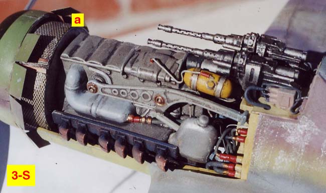
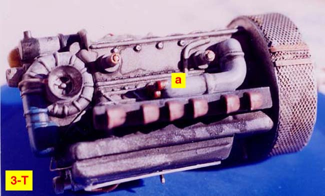
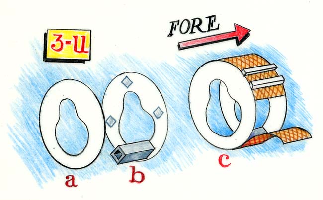
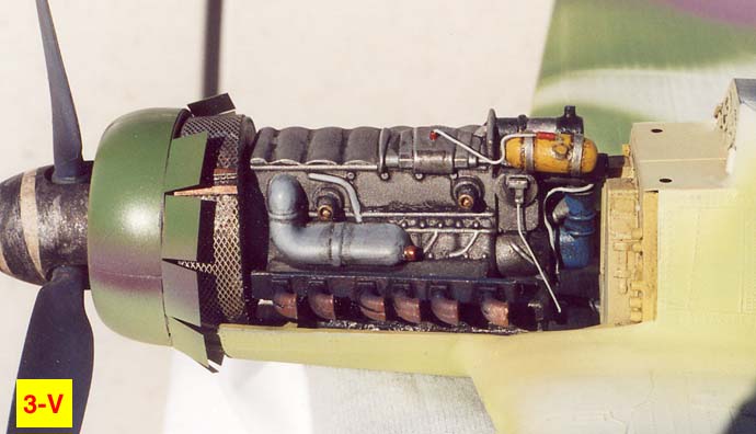
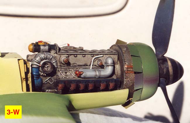
See Photos 3-S and 3-T. Letter "a" in the 3-S photo shows the location of another scratchbuilt part. It was the engine radiator. Altho only a small portion of it would show once all the parts were glued in place, it was quite a prominent section of the completed engine. Neither the RevellUSA or the old Hasegawa kits included the part and it was nix, zero, and nada for Verlinden's detail set, as well. In Photo 3-T at letter "a" you see the starboard side of the kit enginem the scratchbuilt radiator and the location where the three engine hose connectors were . . . ah . . . connected? In other words there were three different pieces of solder hose that would fit into each connector on the starboard side of the kit engine. Also note the dark blue color of the bottom of the engine super charger. This dark blue was quite prominent in the Squadron Signal Walk Around book color photos. Since the radiator was basically a circular disk with some thickness to it, I felt I could use my circle template to made a white twenty thousandths sheet styrene "doughnut". See Photo 3-U. It's another, rather quickly drawn, crude colored pencil sketch. However, I hope it will make it easier to understand just how the large engine radiator was scratchbuilt. However, I should say here that I FIRST made a manila paper pattern of the "doughnut" and trimmed it with scissors until it was the right size and shape to dryfit, dryfit, dryfit, around the engine and check for the fit inside the engine compartment. The hole in the middle of the doughnut would be cut in a shape that would fit over the protruding front section of the engine; the point where the prop hub fit into the kit engine. So, although at letter "a" the sketch shows this shape as a piece of twenty thousandths white sheet styrene, you could also think of it as the manila paper pattern that I started with. Next, I cut and sanded two identical "doughnuts" like you see at letter "a". However, as you look at letter "b" you see that I needed to fabricate a strong "spacer" to hold the two styrene circles the correct distance from each other. In my spares box. . . ah yes, the infamous "spare parts box". . . was a long section of gray styrene, hollow and in the shape of a long rectangle. So I used my razor saw to cut four lengths the same size. Those four pieces were glued in place an equal distance on the "b" circle where you see the gray diamond shapes. At letter "c" you see that I super glued sections of brass mesh around the edges of the two circle "doughnuts". Two horizontal pieces of styrene plastic strips, in several locations around the circle, were attached over the mesh at equal distances, in an attempt to replicate aspects of what I saw in the pictures of the full sized Dora's radiator. The mesh screen was purchased from a local model railroad hobby store, now defunct. It is a brass micro-mesh rectangle from Scale Scenics, a division of Circutron, a model railroading manufacturer in North America. At the end of this part III, I will mention one of the online suppliers for brass mesh.And lastly, see Photos 3-V and 3-W. As you may have guessed, these two pictures were taken earlier in the construction phase, then some of the pictures shown and mentioned previously. But I felt it was best to display them here since the scratchbuilding of the engine radiator was one of the last steps to finish the engine itself. Once I was reasonably comfortable with the overall fit of the engine in the engine compartment, it was a question of attaching all the wires, super gluing in the two machine guns, and attaching and gluing the hoses in place. Most of the exterior of the model was painted before I did any of these steps; even before I glued the engine in place, the machine guns, and attached the engine cowlings in an open position over the engine compartment.
In the last part of this article, Part IV, I intend to discuss the construction of the landing gear, the painting of the camouflage colors, the application of the handmade marking's templates (in order to create an illusion of a faded exterior) and discuss the following: 1) my philosphy for including a photo essay album on the table next to my model in an IPMS contest. And 2) how superdetailing an aircraft model for an IPMS contest can backfire, and therefore lessen your chances of winning rather than enhansing them even though the "degree of difficulty" would be more difficult with all the additional scratchbuilding and opening of panels. And of course, there will also be a couple of other surprises.
Micromark The hobby tools company is located at 340 Snyder Avenue Berkeley Heights, New Jersey, 07922 USA
Internet Trains The online railraod modeling supplier who is located in Brea, California, USA In North America, call: 1 800 369 0878 Outside North America: 714 256 9401
About the Author


FROM: KANSAS, UNITED STATES
I am primarily a figure painter and have been painting figures about 3 years now; still consider myself a novice. However, I started building models in 1965 and as a retired newspaper artist, I now have time to build models all the time, just for the fun of it and as a way to express my creative inn...
Comments
Copyright ©2021 by Rick Brownlee. Images also by copyright holder unless otherwise noted. The views and opinions expressed herein are solely the views and opinions of the authors and/or contributors to this Web site and do not necessarily represent the views and/or opinions of AeroScale, KitMaker Network, or Silver Star Enterrpises. Images also by copyright holder unless otherwise noted. Opinions expressed are those of the author(s) and not necessarily those of AeroScale. All rights reserved. Originally published on: 2007-01-20 00:00:00. Unique Reads: 9076

WEB HOSTING BY


Copyright ©2021 AeroScale and Kitmaker Network, a subsidiary of Silver Star Enterprises
All Rights Reserved. Please read our Conditions of Use and Privacy Policy.
All Rights Reserved. Please read our Conditions of Use and Privacy Policy.