

1⁄32Re. 2000 Heja/J20 Build Guide
Cockpit, Tailwheel & Fuselage
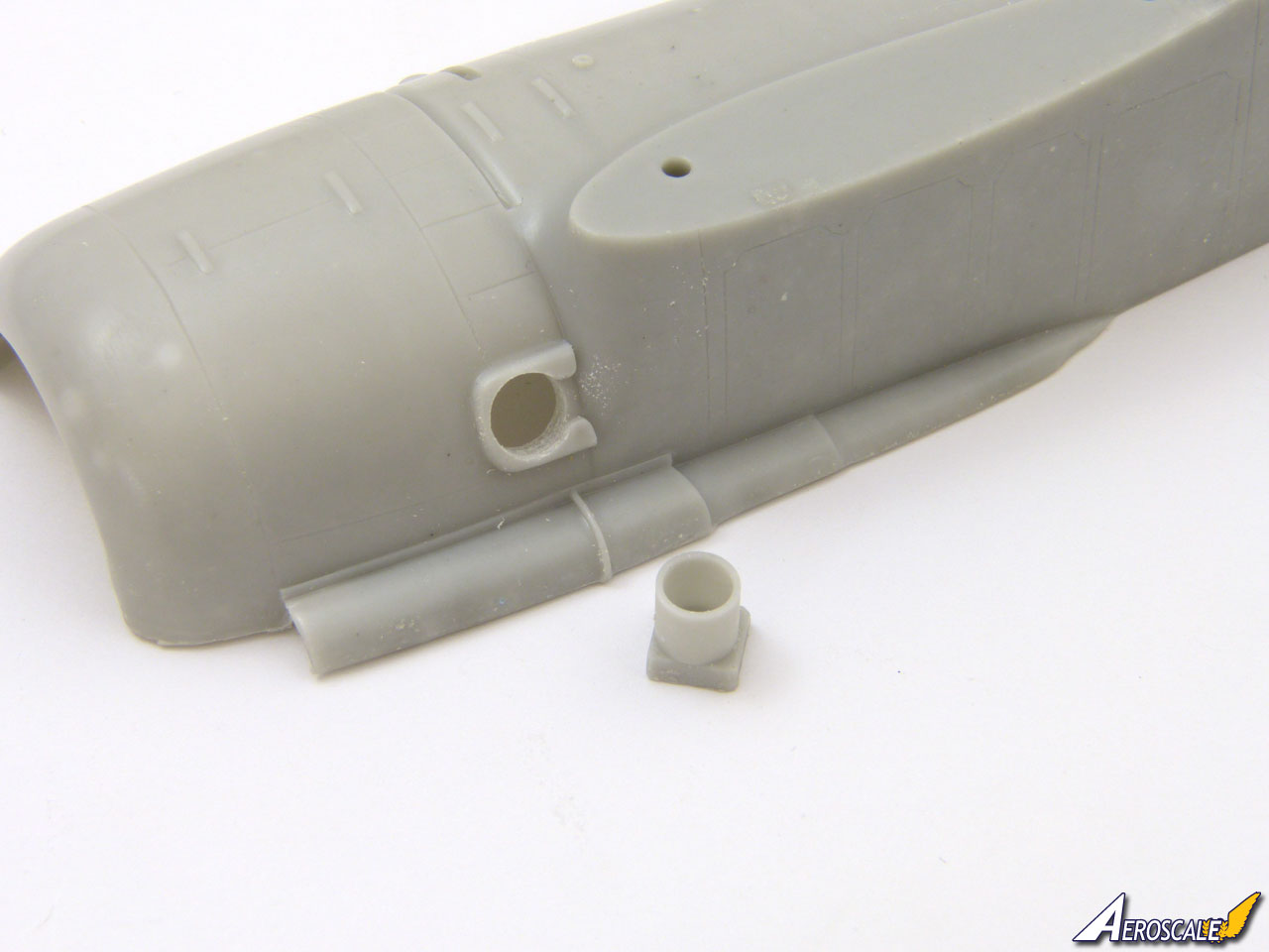
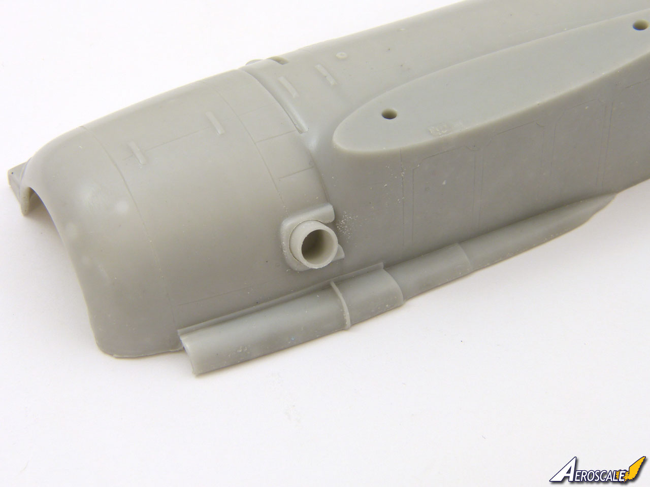
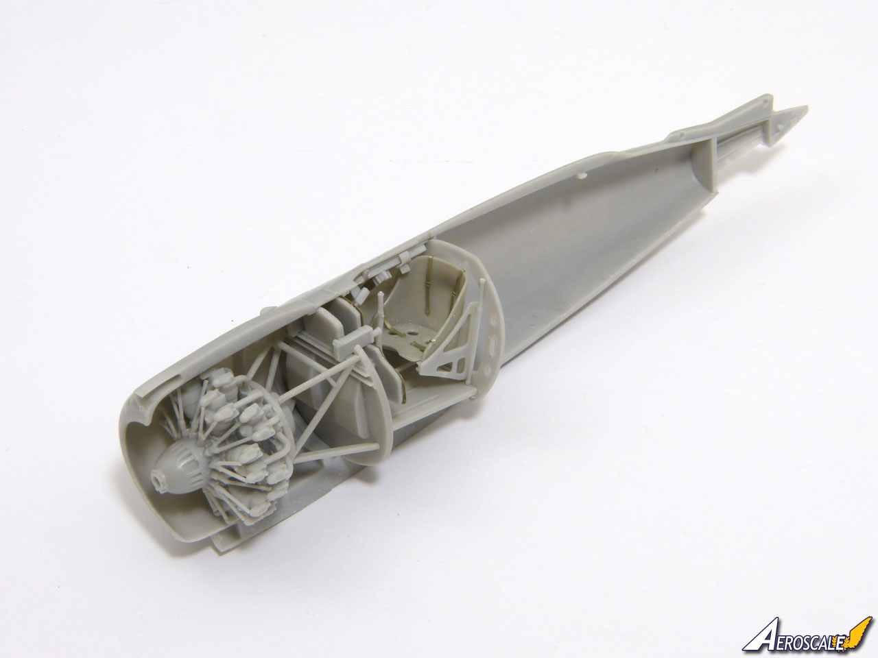
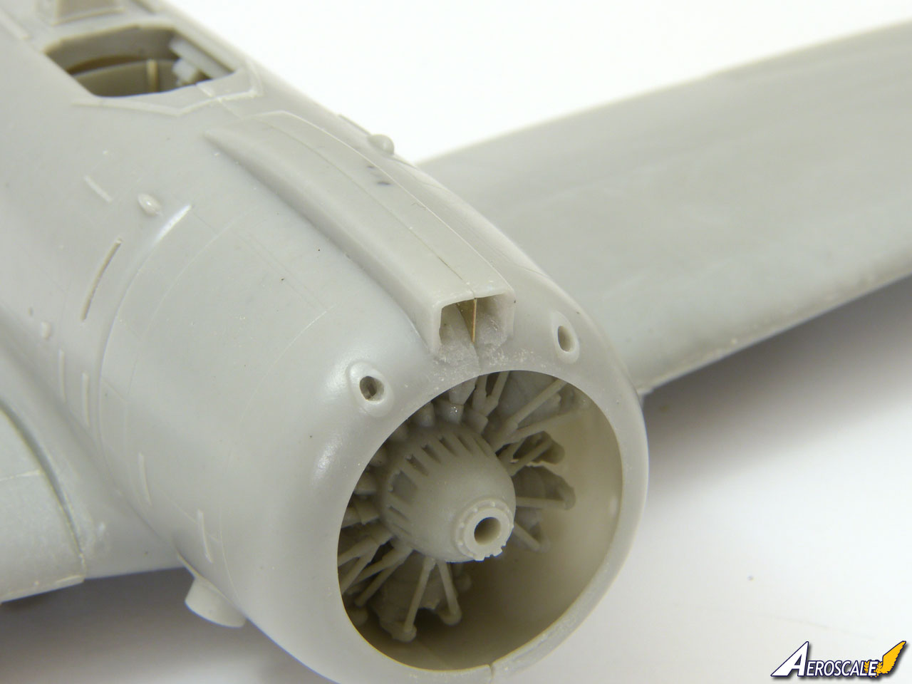
Before starting work on the interior, its wise to check the fit of the exhaust pipes. The holes needed opening up a little on my kit and this is easier done now.The kit contains everything you need to build a satisfyingly busy office, and it looks quite complex on the page because the instructions squeeze in a lot of information. The crucial first task is to establish the correct positions for the main components as a basis for fitting everything else.
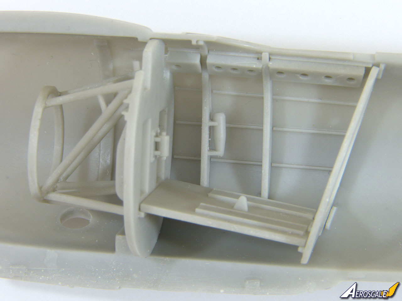
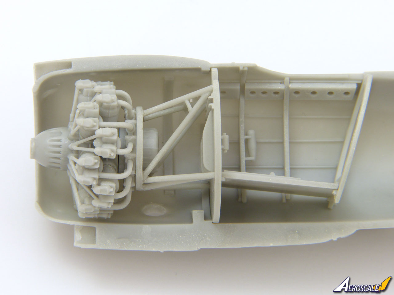
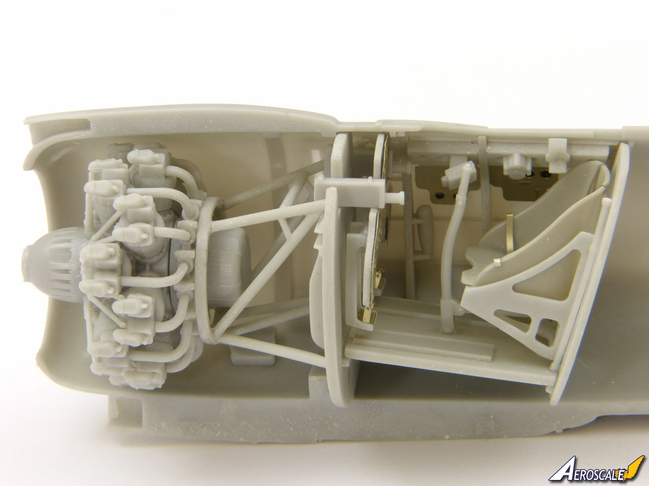
To get an idea of how the interior parts dovetail together, I started by dry-fitting the firewall, rear frame and the floor to establish their positions. With that done, I could be confident that the smaller items would fit around them. The rear frame leans backwards and the floor slopes up towards the front, sitting on the ledges on the rear of the firewall. When the firewall is sited correctly, the front of the engine just protrudes from the cowling.
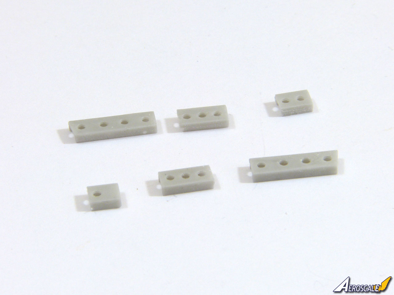
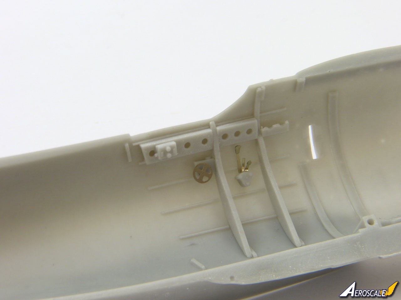
Perforated channels fit between the side-frames under the cockpit sills, and a problem which I discovered later is that the front channels interfere with the machine guns. I trimmed them down when they were already in place, but forewarned is forearmed, and you could modify them easier installing them.
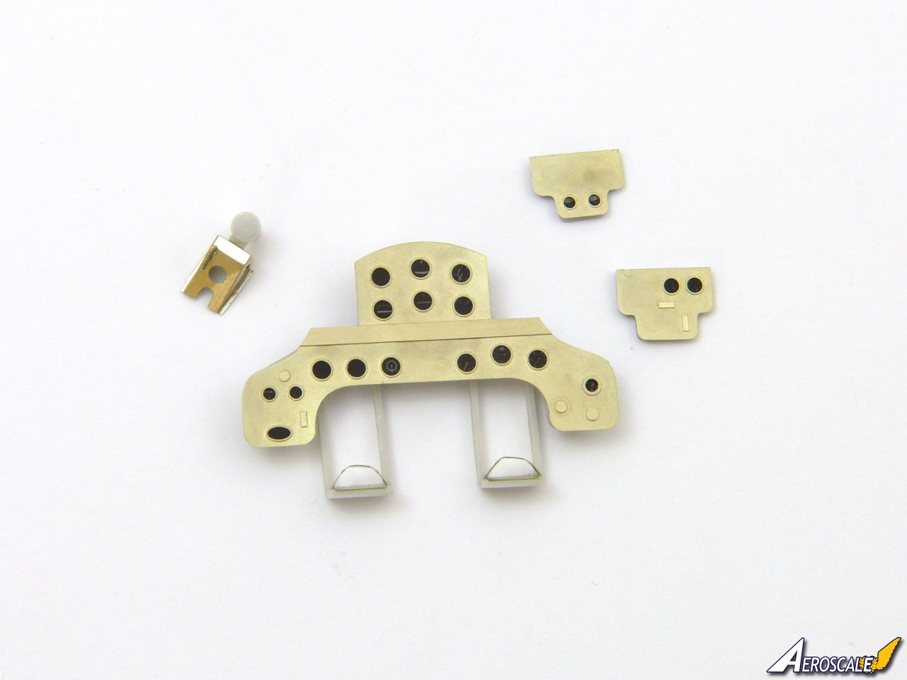
The instrument panel and side consoles are made up of photo-etched fascias with printed films for the instrument dials. These attach to a resin back to form a sandwich. The rudder pedals fit on the back of the main instrument panel and hang beneath it. Each has an etched grip and toe strap.
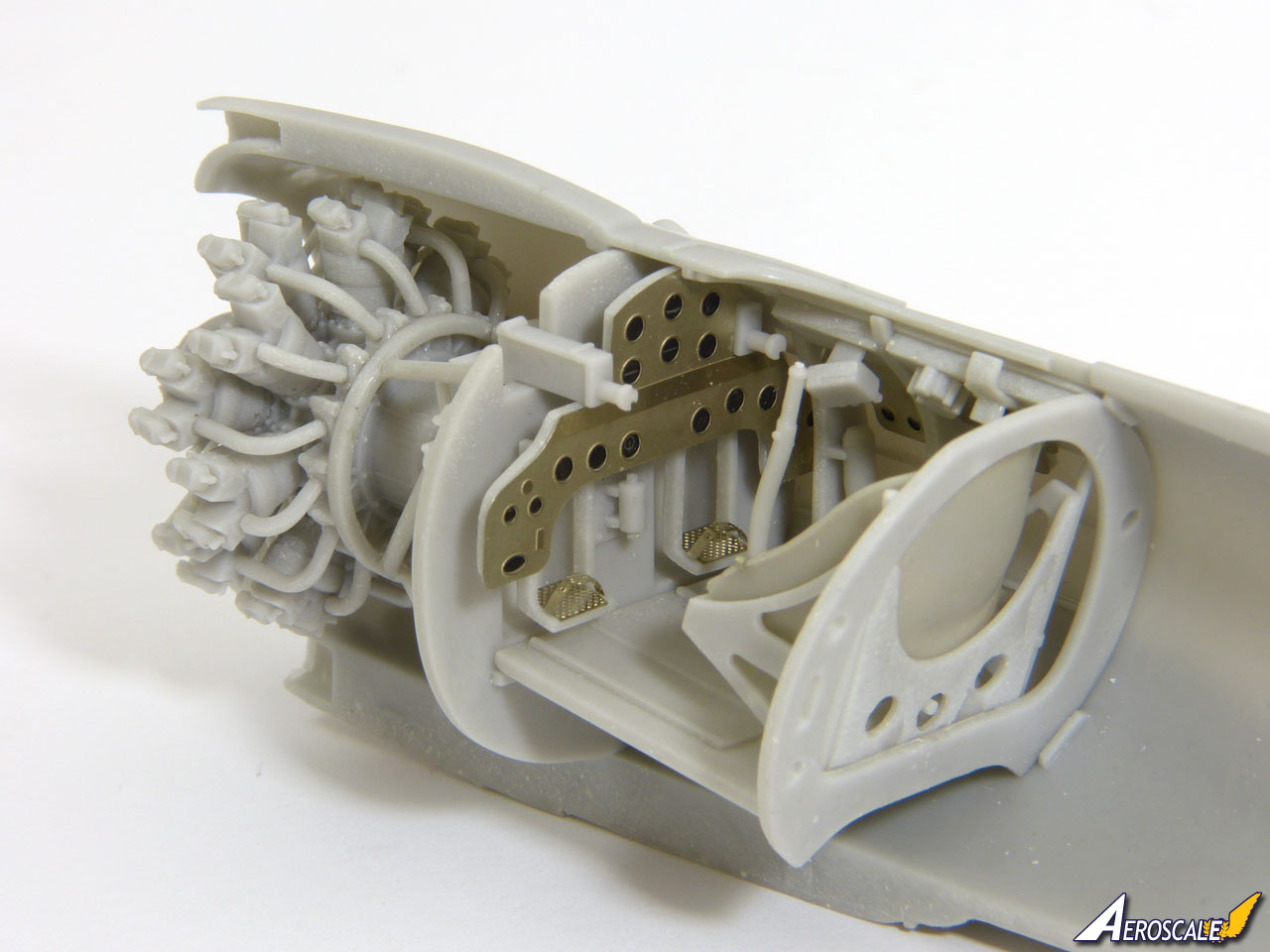
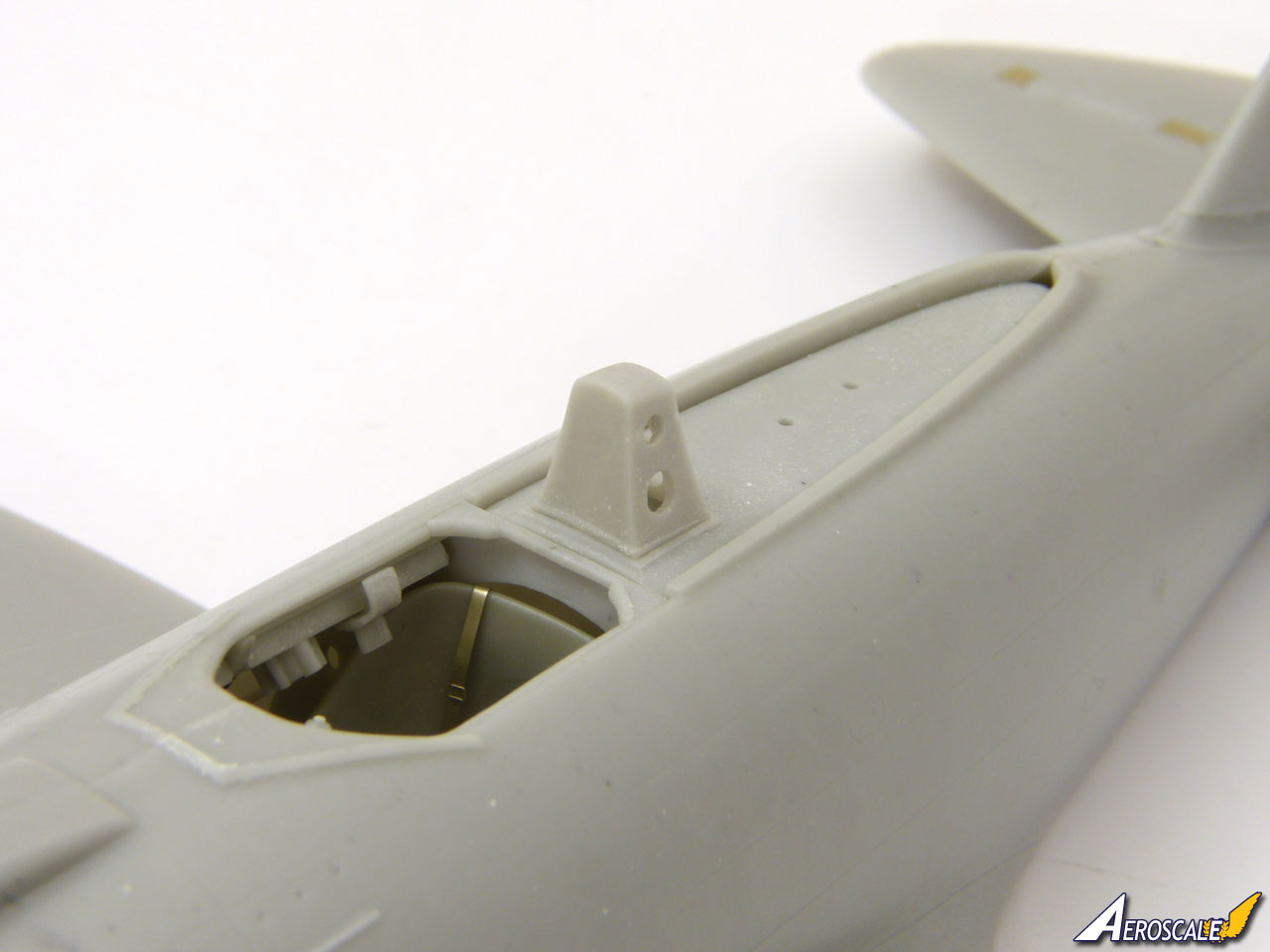
I fitted the side consoles as shown in the instructions, but the position of the main instrument panel is rather vague. Using the machine guns helped pinpoint the location, which ends up matching the diagram in the instructions, tucked in behind the side-frames which partly obscure the lower instruments. That does seem odd, but it positions the rudder pedals correctly in front of the orifices in the firewall.
The gunsight comes complete with a photo-etched mount to fold to shape and a clear resin reflector. The instructions appear to show the mount behind the instrument panel, with the reflector in front. This simply won't work, because the cockpit coaming is in the way. Instead, I chose to attach the mount on top of the coaming, which seems more logical and sets the sight at the correct height. I left it off at this stage to avoid damaging it, only installing it when I was ready to fit the windscreen.
The throttle unit looks pretty complex on paper because each lever is made up from three etched parts. Two of these are actually thickeners to build up the knobs, so you could simplify things by just applying a drop of white glue to form each knob.
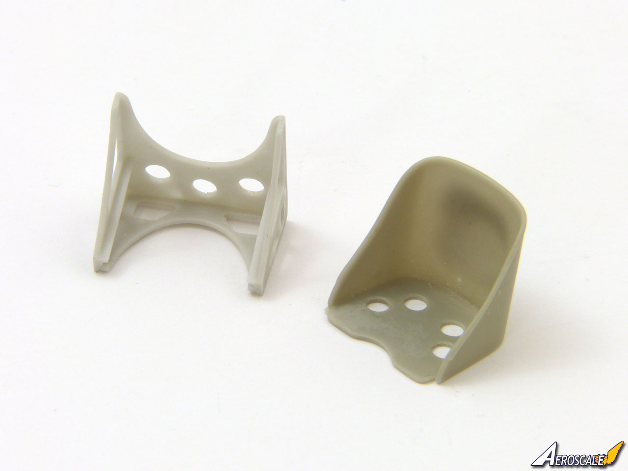
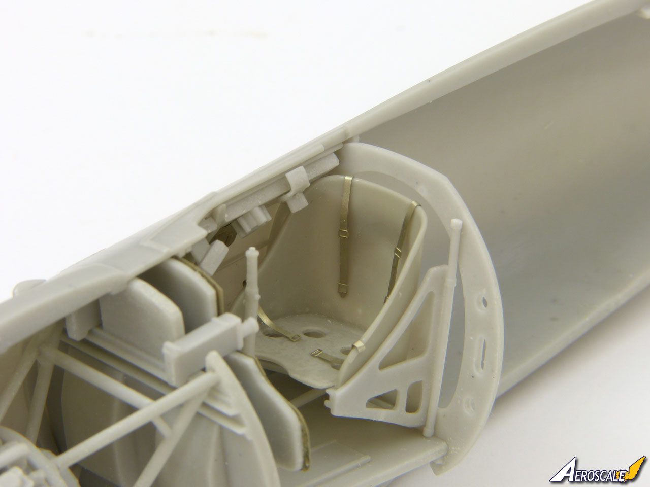
The seat fits in its mounting frame neatly, which in turn attaches to a pair of rods. An etched harness is provided, but it does seem rather undersized, so you may choose to replace it.
Attach the control rod to the base of the joystick and glue the column to its mount on the cockpit floor with the control rod passing under the pilot's seat.
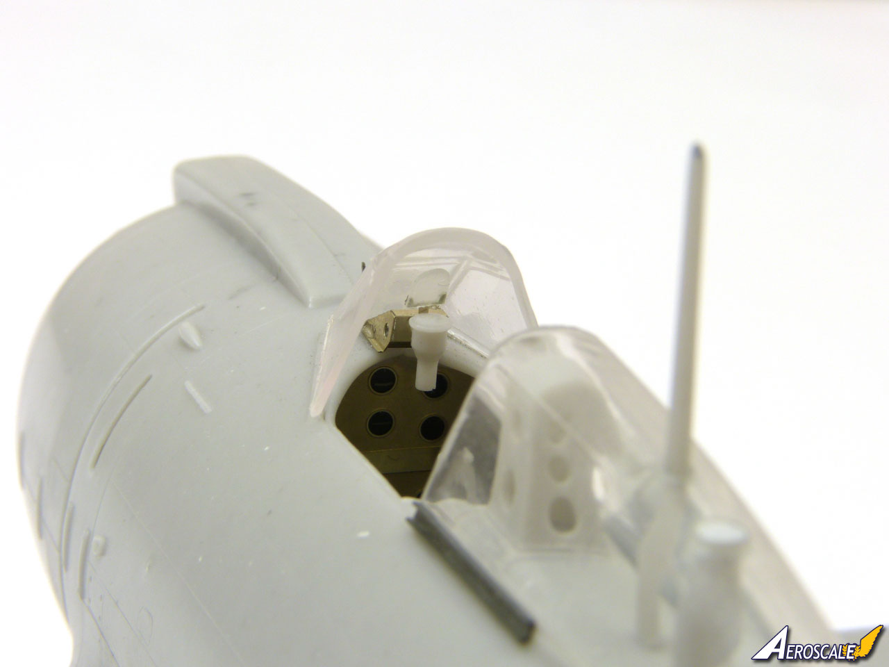
The rear decking can be built in three styles, depending on which nationality aircraft you opt for. The parts are designed to cater for all three options, so you'll need to fill holes as appropriate. Check the alignment of the radio mast and the fuel tank filler pipe behind it. I left the rear decking loose at this stage to avoid the aerial mast getting knocked. You can slot it in without difficulty after the fuselage halves are joined.
The small brass etched fret provides a pair of brackets to fit on the headrest. They don't look at all comfortable and I pity any pilot who had his head bashed against them! I found them too large to fit as shown in the instructions, so I took the shorter one and mounted it at the base of the headrest and then cut down the long one to fit it at the top.
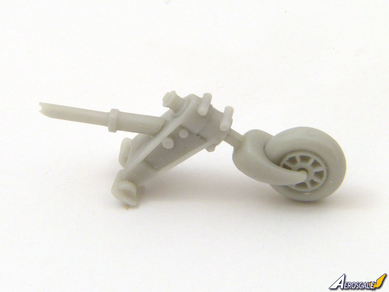
You could install the tailwheel before joining the fuselage halves, but risks it getting knocked during later assembly, so I assembled it and just checked the fit and left it off until Id attached the wings and tail. The strut attaches to two small brackets that mount on the front wall of the tailwheel well.
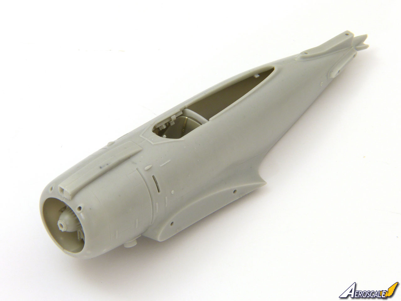
After one last check to make sure I hadnt forgotten any interior parts I installed the engine and glued the fuselage halves together. Once they were dry, I cleaned up the opening for the intake above the cowling ready for its photo-etched splitter.
I fitted the vertical fin, but left off the rudder until later.
The instructions indicate to fit the canopy in place at this stage, but I preferred to leave it until Id finished work on the wings and tail.
About the Author


FROM: NO REGIONAL SELECTED, UNITED KINGDOM
I've been modelling for about 40 years, on and off. While I'm happy to build anything, my interests lie primarily in 1/48 scale aircraft. I mostly concentrate on WW2 subjects, although I'm also interested in WW1, Golden Age aviation and the early Jet Age - and have even been known to build the occas...
Copyright ©2021 by Rowan Baylis. Images also by copyright holder unless otherwise noted. The views and opinions expressed herein are solely the views and opinions of the authors and/or contributors to this Web site and do not necessarily represent the views and/or opinions of AeroScale, KitMaker Network, or Silver Star Enterrpises. Images also by copyright holder unless otherwise noted. Opinions expressed are those of the author(s) and not necessarily those of AeroScale. All rights reserved. Originally published on: 2018-10-10 00:00:00. Unique Reads: 14684

WEB HOSTING BY


Copyright ©2021 AeroScale and Kitmaker Network, a subsidiary of Silver Star Enterprises
All Rights Reserved. Please read our Conditions of Use and Privacy Policy.
All Rights Reserved. Please read our Conditions of Use and Privacy Policy.