1⁄48Kitty Hawk MiG-25PD Feature Review
Building the MiG-25
Construction of the MiG-25 appears to follow fairly straight forward conventions. I will step through the instructions here, on a step-by-step basis. Please note, I have included some basic alternate construction thoughts here, as well as outlined some of the accuracy issues as appropriate to each step. I will be preparing a more detailed “builder’s guide” to this kit with more detailed construction suggestions as well as a detailed correction/issues/accuracy list where you the modeler can decide for yourself how much effort you want to put into the build of your MiG-25 project. I understand that modeling is ultimately a personal hobby, some just want a nice representation of a MiG-25 in their collection, and some want an ultimately accurate MiG-25 in their collection. So in light of that continuum, I’ll present as much information as I can and let you the modeler choose your path according to your personal preferences.Step 1: Build the KM-1 ejection seat – basic color callouts are included, although the seat is called out to be the same color as the cockpit in the next step. This is incorrect. Consult your references and online photos of the KM-1.
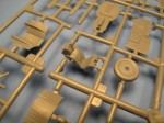
Step 2: Cockpit construction and painting. All variants of the MiG-25 cockpit should be the infamous bright jade blue-green color. Alternate parts are included for PD and PDS instrument panels (see notes later on building a PDS).
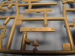
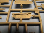
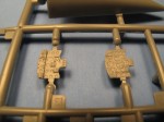
Step 3: Build the nose wheel well and nose gear strut. The instructions would have the strut added to the wheel well at this point. I would save the addition of the strut until later in the build to facilitate easier painting of the airframe, and to protect from knocking parts off the model during handling.
Step 4: Assemble the forward fuselage. Trap the cockpit tub and nose wheel well between the forward fuselage halves. The instructions also call for nose weight to be added. The ball bearing can be used at this point, but many modelers will find alternate spots and types of nose weight to be used.
Step 5: Assemble the outer intakes. Here is the big fault in the kit. The intake fronts are shown with FOD style doors being built in a dropped position. There are mounting lugs inside the intakes to position the “doors” accordingly. Unfortunately this is just not correct. Unlike the later generation Russian aircraft, most notably the MiG-29 and Su-27, the MiG-25 does not feature retracting FOD doors (or the auxiliary intakes that accompany this feature) that protect the engines during takeoff from unimproved airfields. The MiG-25 has fixed intake ramps and rather large intake trunks to facilitate airflow to the big engines. Regardless of what the manufacturer intended, the parts for the “doors” and photo-etched cover are roughly the right dimension, but should be represented as ramps and not closed doors. Unfortunately correcting the doors to ramps only solves part of the problem as no intake trunks are included in the kit. Correcting the “doors” into ramps would be relatively simple, but would expose the inside of the main fuselage back to the afterburner sections. Ultimately the intake trunks will be something that either have to be scratch built or an aftermarket alternative will have to be sourced. This is also one of the only areas where I noted visible knock-out pin marks – inside the intakes.
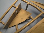
Note the mounting strips on the inside of the intakes, these position the intake "doors."
The step continues with adding the forward intakes to the forward fuselage completed in step four. Normally, I would not add the intakes until the rear fuselage was ready to make sure everything aligned correctly. This will require some experimentation and will be covered in more detail in the builder’s guide.
Step 6: Build the port side main landing gear strut. Here is an interesting feature of the kit. The MiG-25 has split main landing gear struts, with a joint half way between the wheel and the pivot point of the landing gear strut. In order to replicate this feature of the real aircraft, each strut is composed of four main pieces sandwiched around an inner metal brace. The braces are “handed” and each are made from a different color of metal in order that the correct “handed” brace is used for the correct gear strut. An additional six parts finish the detailing of the gear strut. The finished gear strut appears to be a very good representation of a complex assembly – especially for an out of box set of parts. The instructions would also have you add the main wheel at this point as well. I would save this part for final assembly, adding the wheels after the gear struts had been added to the finished assembly.
A nitpick would be that the mold seams on the tires are represented as rather heavy panel lines versus finely raised detail. If it bothers you, it is a virtual certainty that some aftermarket company will deliver a nice set of resin replacement wheels in the not too distant future. And in fact, there are already photos of a CAD model for resin replacements that have been doing the rounds on various forums

Step 7: Build the port main wheel well. The main wheel wells are nicely boxed assemblies that correctly represent the depth and shape of the MiG-25’s main gear wells. The wells are molded in five parts including detail that would match to the outside of the fuselage. This is handy because when the invariable aftermarket wheel well becomes available, no kit detail will need to be removed in order to facilitate fitting the aftermarket parts.
The main gear strut assembly is shown being added to the wheel well at this point. Again, like the nose gear, I would save this for final post-paint assembly.
Step 8: This is the starboard duplicate of steps 6 & 7. Again, save wheel and gear strut assemblies aside for final assembly.
Step 9: Build the afterburner assemblies. The large afterburner sections are represented with a proper depth. Each tube is built from top and bottom halves with flame holders at the back. The inner, actuated burner petals are added and then the outer petals are built around these. The tubes have the proper layered corrugation effect, but will have some problematic seams to remove, especially given the large diameter of the burners.
Here is perhaps the other big accuracy issue. The outer petals are the “long” type that are featured on the MiG-25R and B type aircraft, and are NOT correct for a MiG-25P of any type. This is much like the differences between “short” and “long” J-79 engines on a F-4 Phantom. I view this as much less severe than the intakes for two reasons. First, only the hard core Russian aircraft fans are going to know the difference and second, these are parts that I would usually swap for aftermarket anyway not only for the outer details, but given companies like Aires’ ability to represent burner cans (see their fantastic MiG-23 products), an aftermarket replacement would have likely made sense regardless of the inaccuracy.
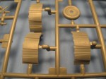
Step 10: Add the subassemblies to the main fuselage. The main gear wells and afterburner sections prepared in steps 6-9 are added to the main fuselage at this point.
Step 11: Main fuselage assembly. Upper and lower rear fuselage halves are joined at this point as is the forward fuselage assembly from step five. It is at this point that I would actually add the outer intakes to ensure alignment between the various fuselage parts, instead of assuming that the intake outlines and forward fuselage are all going to perfectly align with the rear fuselage.
Curiously, intake vanes are added at this point. These are prominent vane trees that are sensors inside the main intakes. These are very visible in the actual aircraft, but are hidden behind the faux FOD door.
Step 12: Lower fuselage details. Gear doors, lower speed brake, antennas and similar parts are added at this point. Also added are the ventral fins and the horizontal tail planes. Like the landing gear struts, I would save the vast majority of these details for final assembly after the airframe was painted and nearly finished. In fact about the only thing I would add at this point would be the ventral fins. Even the horizontal tail planes should be added later, as the mount via a single pivot point, and will be subject to being knocked off during assembly.
Step 13: Upper fuselage details. Upper speed brake, brake chute fairing and the forward fuselage spine are all added in this stage.
Step 14: Wing assembly. Upper and lower wing halves, control surfaces and wing fences are all built into left and right subassemblies. Also added are the wing tips. Because the MiG-25P has a longer wing span compared to the shorter span of the MiG-25R, Kitty Hawk has built a cut in the outer wing to allow these parts to be swapped. This is one of the few portions of assembly that gives me cause for concern, as the tolerances will have to be just right for these parts to fit. Parts are oddly notched which make sure they assemble correctly to each side. At minimum care will have to be used here to ensure that all of the fine panel details are not sanded out in the blending process.
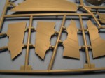
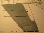
Additional internal ribbing has been added to the inner surfaces of the wing parts, presumably to provide structure. This creates a series of very slight sink/shrink marks on the outer surfaces of the wings. Care will be required to remove these marks without obscuring the nicely done panel details.
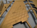
Step 15: Airframe assembly. Wings and vertical fins are added to the fuselage assembly. Instructions also show pylons being added at this point, although like most of the non-airframe parts, I would add these during final assembly.
Step 16: Nose assembly. The primary differences between ALL MiG-25 variants are forward of the frame that is essentially at the tip of the windscreen, this section of the nose is molded separately from the remainder of the nose. This facilitates the tooling of all of the MiG-25 versions without the need for tooling completely new fuselage halves.
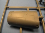
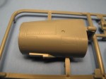
The kit features a complete radar set for under the radome (should you choose to display the radome off the aircraft). The radar parts included are representative of the Smerch radar that was characteristic of the MiG-25P and not the Sapfir-25 characteristic of the MiG-25PD/PDS. Alas, I rarely display these details in my projects, so my radome will end up glued on. Undoubtedly, an aftermarket company will produce a resin (and more detailed) replacement for this detail if this is something of concern for you.
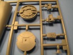
I’ll take a deeper look in my builder’s guide, but I expect this is also where I would vary from the instructions as I learned a LONG time ago to build half to half vs. front to back. So I would add the forward nose sections (parts PD1 and PD2) to the main forward fuselage sections (parts F13 and F14) assembled in step four. This allows the curvatures to be matched for each set of parts and minimizes the filler required.
Step 17: Radome and nose details. The radome halves are assembled and added to the nose subassembly from step 16. The IR fairing is added and the alternate parts for the searchlight (a characteristic of the PDS – as it was a hold-over feature from the P) are added as well.
Step 18: Final aircraft assembly. The nose is added to the main fuselage assembly from step 15. Canopies are added and the aircraft is considered complete at this point.
The remaining un-numbered steps detail the assembly of the weapons and pylons. There’s nothing terribly remarkable about any of the assembly steps but there are a few notes worth making regarding the weapons included in the kit:
- The R-40 missiles that are one of the main characteristics of the interceptor MiG-25s are nicely done, with the exception that the exhaust nozzles for the rocket motor are under-represented. Because there is a receiver unit in the tail of the missile, the rocket exhaust comes out nozzles in the sides of the missile. These exhausts are in line with the trailing edges of the main fins. Bumps on the missile sides are in the place of the exhausts, but should be more pronounced. Like the wheels, if this bothers you, it is a virtual certainty that a finely detailed set of resin R-40s will be released in the nearest future.
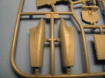
- The items listed as EW pods are in fact anti-flutter weights for the wingtips. These are NOT optional parts, these should be on ALL MiG-25 models. These are also the LATE style of anti-flutter weights – this is important because of the impact it has on what variants you can build.
- Ignore the instructions for the bombs – FAB-1500 and FAB-500, the pylons, and similar parts (essentially all of page 18). These are not appropriate to any load on the MiG-25P family. It’s nice they’re included, and they’ll be very useful for the MiG-25R series release in the near future, but for now, put them in your spares box. They’re not available in a lot of other kits, so it’s nice to have extras of those.
- Not mentioned in the instructions are the Kh-58 anti-radar missiles. These are the main weapons of the MiG-25BM anti-radar aircraft. While one has not been announced or shown by Kitty Hawk to date, I’d say the inclusion of these parts indicates that a MiG-25BM is forthcoming.
- Also not mentioned in the instructions are the R-73 missiles. Not sure why these were included as these are not appropriate to any MiG-25 variant. Again, throw them in the spares box.
- The R-60 missiles included in the kit aren't great. The forward fins seem to be molded over the front of the seeker head, which is not correct at all for that missile. Fortunately there are at least three good aftermarket options for the 1:48 R-60, Eduard's being the best in my opinion.
MiG-25PD Only!
While this kit advertises itself to be a MiG-25PD/PDS, it is really ONLY a MiG-25PD. The MiG-25PDS version (as we introduced early on) is a field-upgrade to bring MiG-25P aircraft up to the MiG-25PD standard. While it appears to be only a nose change – which is identical to the MiG-25PD, the MiG-25PDS retained a number of other characteristics of the MiG-25P.Two primary differences:
- The wingtip anti-flutter weights are different on the MiG-25P. Only the later type anti-flutter weights are included.
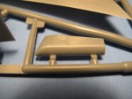
- The parachute brake fairing on the MiG-25 came to a pointed tip where the MiG-25PD fairing was ogive. It appears that the pointed parts are included in the kit – in the form of parts B3 and B5. These would replace parts E9 and E10 in step 13 – but no reference is given in the instructions.
- There are a number of far less noticeable panel changes and similar detail differences, but these are hard to detect even for the hard core Russophile!
This only impacts you if you’re making a MiG-25PDS – and then unless you’re hard bent on a particular aircraft, just chose a different number and build a MiG-25PD.
Given the layout of the PD tree of parts – with big holes that appear to be gated off, it would appear that there is possibly a MiG-25P in the future, as these holes would suggest that the necessary alternate forward fuselage halves could be made at a later date (the MiG-25P had a slightly shorter forward fuselage and a completely different panel line arrangement in that section of the fuselage). We can HOPE that when they release a MiG-25P in the future, that they take the time to include these other parts as well, as they will definitely be required for a MiG-25P release.


