

1⁄35MH-60S Knight Hawk
15
Comments
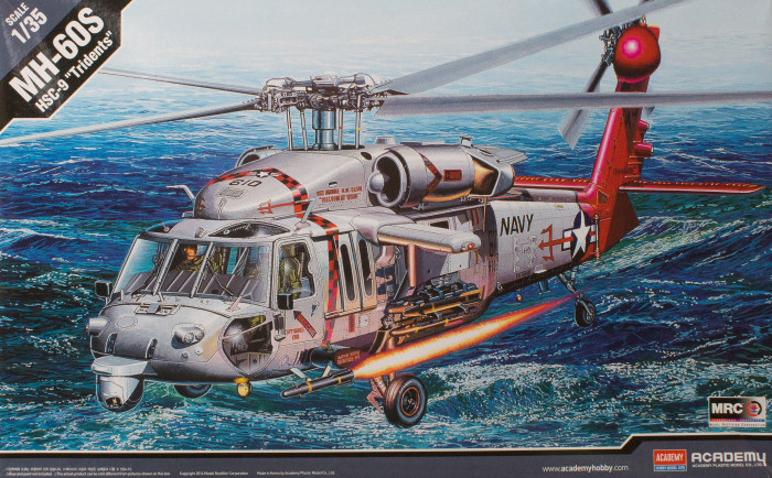
The Kit - Academy 1/35 (Kit #12120)
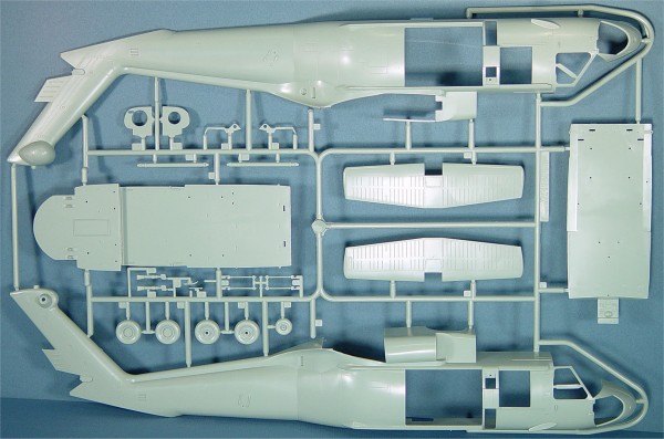
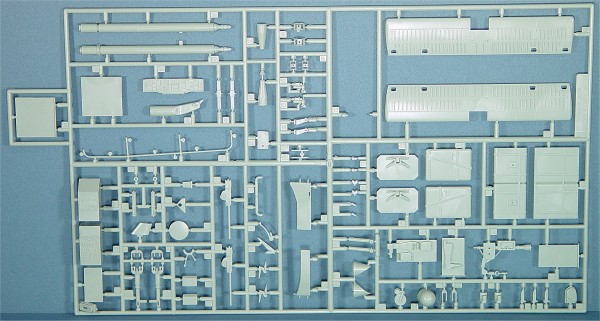
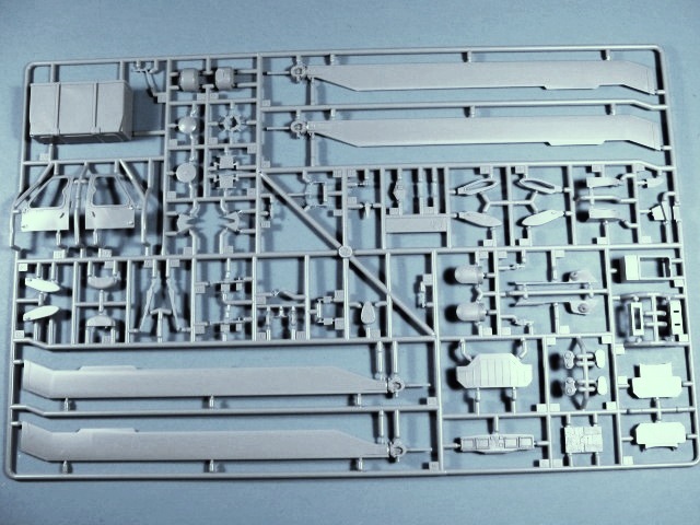
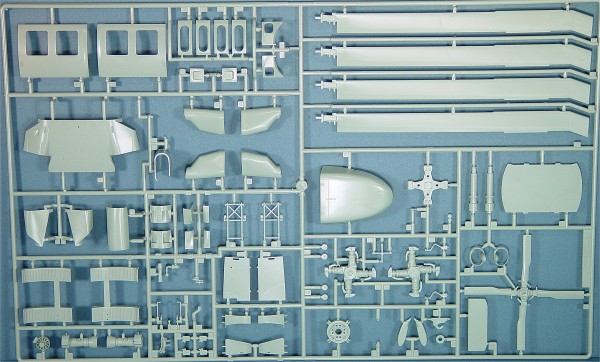
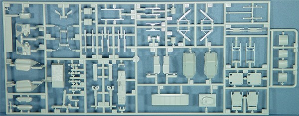
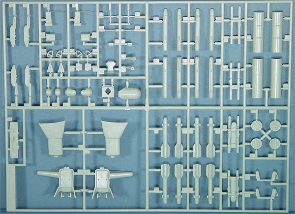
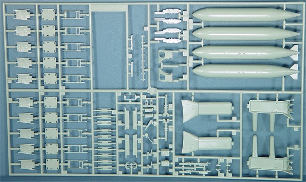
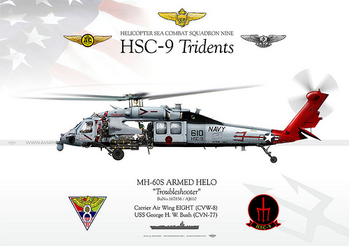
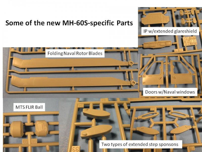
The latest version of Academys H-60 series is the US Navys MH-60S. The kit contains seven large sprues in gray plastic for the main helo parts and one sprue of clear parts. Also included is a very large decal sheet including three aircraft: AJ 610, HSC-9 aboard the USS George H. W. Bush; VR70, HSC-21 from Naval Station North Island, San Diego, CA; and BR41, HSC-28, Norfolk, VA. This boxing contains all the sprues from Academys earlier H-60 releases, plus a new sprue (M) that contains all the Navy-specific parts to build the MH-60S. With all the earlier sprues in the box, you could actually build almost any version of US Army or USAF H-60 as well. The kit is rounded out with a 20-step instruction booklet that lays out assembly very well.The Build
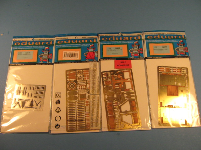
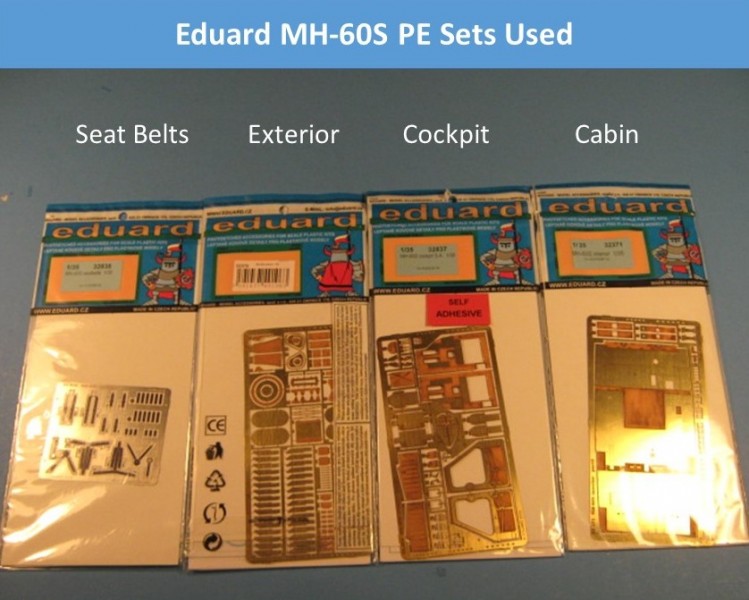
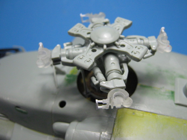
For this build, I have decided to go all out with five Eduard PE sets ( 4 four new ones for the MH-60S: Cabin Interior, Cockpit Interior, Seatbelts, Exterior; and a Remove Before Flight Tags set), Cobra Companys MH-60S Detail Set and console from their MH-60M set, MH-60S Rotor Hinges printed from Shapeways, Live Resin M240H machine guns mounts (Dillon Aero Black Hawk Window M240H Mount, 35171) with SMP Designs M240H machine guns also printed at Shapeways, with some scratch-building to fold the tail assembly and main rotors and add some missing details on the interior. I also chose to build the colorful first markings option; AJ610, the CAGs (Commander of Air group) bird from HSC-9 Tridents aboard CVN-77 USS George H. W. Bush. Follow along and I will point out what I have done.Step 1: This step builds the main rotor head and rotor blades. Build the head as shown, but leave the blades off until later. The blades will be modified to be in the folded position using the Shapeways MH-60S Rotor Hinges which were drawn in CAD by our very own Matt Leese. They are very nice and allow the rotors to be folded and look pretty realistic, more on them later. I also leave part B63 off so the rotors can be removed later for storage or transport.
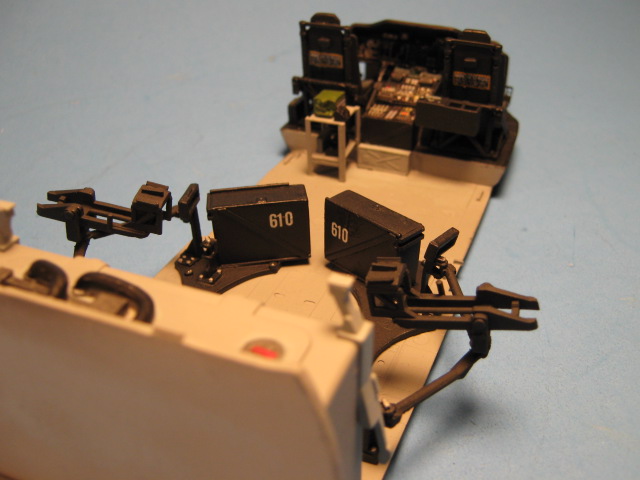
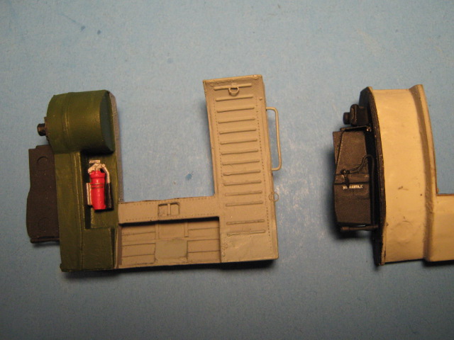
Steps 2-4 can all be done as shown. I did leave off the upper gunners seat support (D5) in step 3 as it will be added after the Eduard interior parts. I also detailed the gunners seats with decals for the aircraft number 610, after painting them. Most removable parts from the interior are labeled with the aircraft number so they can be identified and replaced back on the same aircraft. It also discourages your buddies from borrowing them for their aircraft.
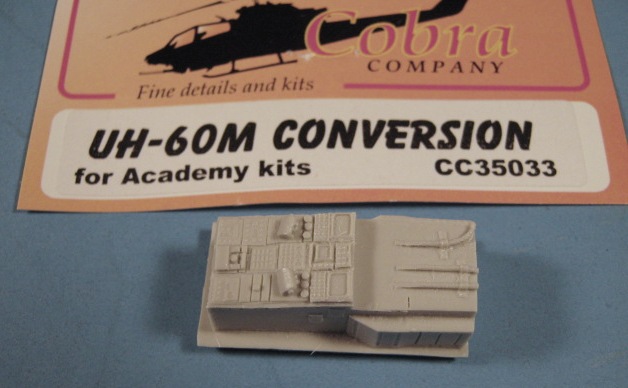
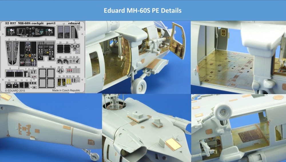
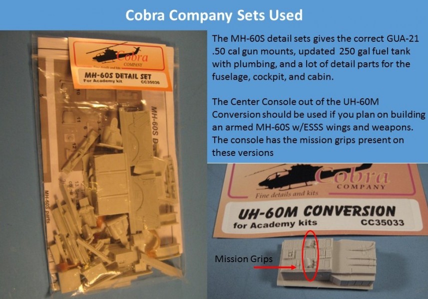
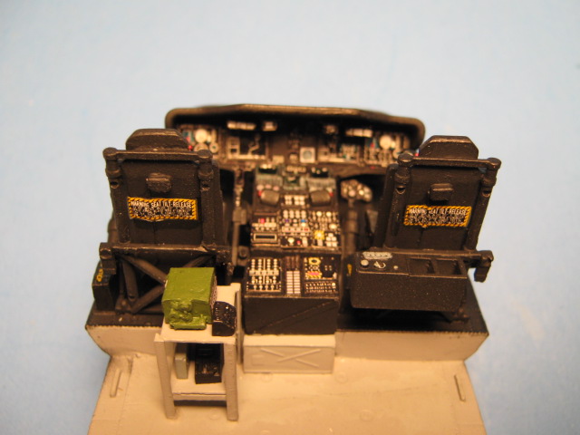
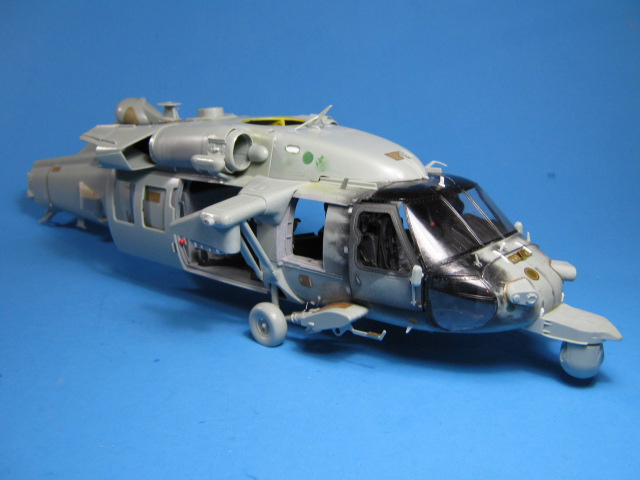
Step 5: Here I deviated from the instructions. I sanded smooth the front side of the instrument panel (IP, part M3) so the Eduard IP could be installed. I also did not use parts M14 or M2 for the center console. I replaced the center console with the console from the Cobra Company (CC) MH-60M set. I did this since the CC console has the mission grips present that are used on all armed MH-60S helicopters. Academy left these parts off. The Eduard IP is very nice with self-adhesive backed parts to allow quick and easy assembly. Simply remove them from the fret and stick them to the base IP face and build it up as you go. I did find a few of the pieces needed a little super glue to get them to stay in place though. In the end, it produces a very nice IP with the proper faces to the MFDs (Multi-Function Displays) and all the right gauges and dials represented in fine detail and good colors.
Step 6: Skip this step as none of the weapons or their mounts and ammo boxes in the kit are correct for an MH-60S. The MH-60S is only authorized to use the M240D/H 7.62mm machine gun from the gunners windows and the GAU-21 .50 cal gun system out the cargo doors. The GUA-19 (M134) minigun (as in the kit) is not authorized for use on the aircraft and the kits .50 cal cargo door mounts are all wrong. The Cobra Company MH-60S Detail Set provides the proper GAU-21 door mounts and ammo boxes in very nice resin and rubber for the ammo feed chutes. For the M240s you can either get them from Live-Resin (LRE-35171 UH60 Dillon Aero Black Hawk Window M240H Mount), or get just the guns at Shapeways from Samofalov Prototyping Models (SPM, SPM-35-026) for a different version with forward handgrips installed. I decided on the SPM guns with Live Resin mounts.
A note on weapons: The GAU-21s and/or the M240D/Hs are not always mounted. The same is true of the ESSS wings and weapons on them. Weapons loadout is mission specific and changes all the time. You can choose almost any weapons combination or no weapons at all and still be correct with this aircraft as it is used in many different roles. Look at your references and decide how you want to arm it, or not to at all.
Step 7: Build as shown for whichever version you choose.
Step 8: Build as shown if you will be using the armed version with Hellfire missiles. I choose to use the Hellfires rack on one side and an M200 19-shot FFAR (Fire and Forget Areal Rocket) pod on the other. This option is not shown in the instructions, but is used operationally by the USN. The rocket pod parts are included on sprue K from the earlier AH-60L DAP kit (K24, K25, K26, K27).
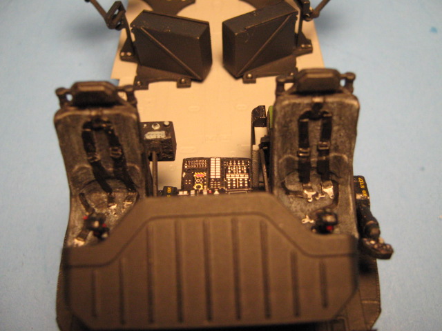
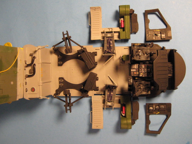
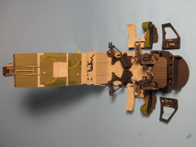
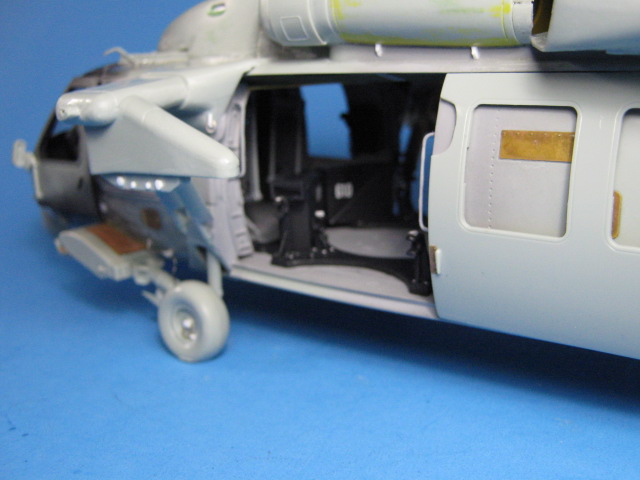
Step 9: Here I deviated from the normal assembly guide again. At this point, I installed all the interior Eduard PE parts. These parts replace or cover almost every surface on the aircraft interior. You get a very nicely detailed roof panel with separate pieces for opening panels, tie-downs, and the transmission drip pan. I added the drain lines from the drip pan with thin telephone wires (yellow wires). You also get a very nicely detailed floor panel with attachment points for seats and tie downs along with a nicely detailed cover for the underside cargo hook. I also used the gunners sidewalls and very nicely done rear fuel tank and wall from the CC set at this point. All the parts fit in perfectly with no issues and went together well. In the cockpit set, you get very nicely detailed floor panels and details throughout. Also, Academy has another error here, you should only install one of part M28. This is to control the FLIR on the front of the aircraft. In the armed helo configuration, there should only be one on the left side of the aircraft. Other versions use two controllers, but the parts to build them are not included in the kit. I also used the CC pilots seats, collectives and cyclic grips, and heating vents in the cockpit. Lastly, I built the electronics rack that is used in the armed helo version. It is a short rack behind the pilots seat on the left side. I built it out of L-shaped rod and sheet styrene. I filled it with some left over resin radio and computer component parts to represent the electronics on it.
Step 10: If you are going to show the engine, build as shown. I skipped this as I will not be showing it. I built the rear landing gear as shown, but shortened the pins for the tail wheel so it could be added later.
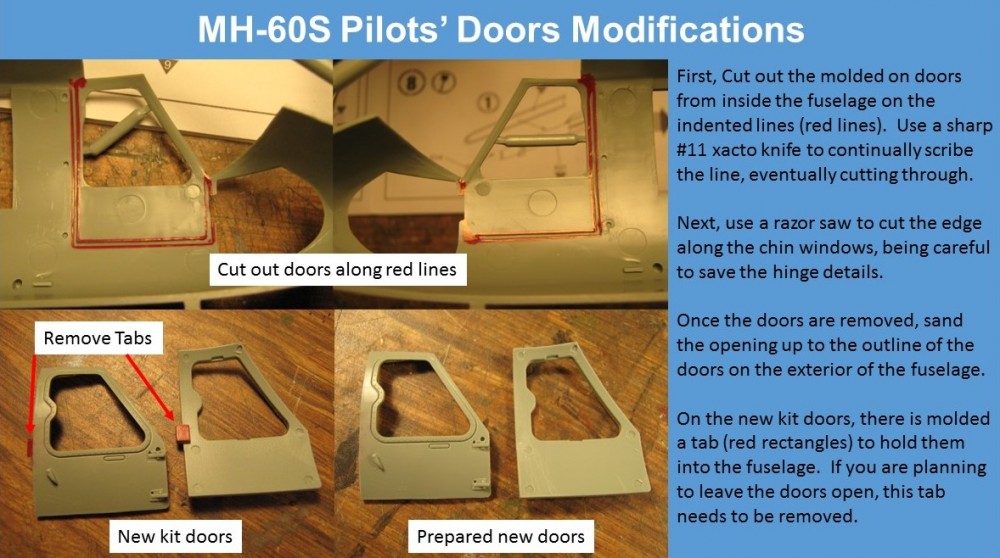
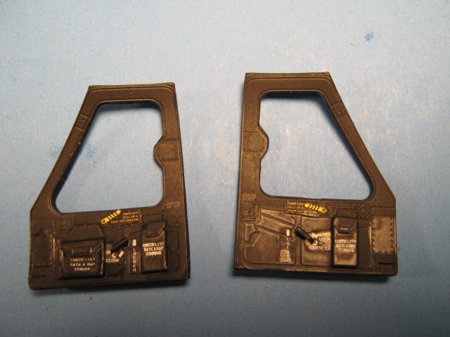
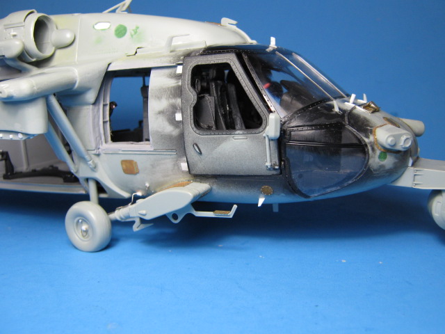
Step 11: This step involves cutting off the molded on doors so you can install the new naval doors. There are score lines on the inner surfaces to make this easier. I followed the score lines and ran a sharp #11 xacto blade along them with gentle pressure multiple times until the blade came through. A little clean up with a sanding stick and they came out great. Use a razor saw to cut the forward part of the door off carefully, leaving the small taps with the hinge details. A note here, the new doors (M60, M61) have a tab on them to hold them in place in the fuselage. This tab is not present on the actual door. If you want to display the doors open, remove this tab and sand the inner door surface flat. Also, there is a corresponding slot in the kit gunners sidewalls (B28, B29) to accept this tab. If you are using the kit sidewalls, fill this slot as well. Here I used more of the Eduard cockpit set to detail the doors. This included a very nice inner door piece, inside handles, and map cases.
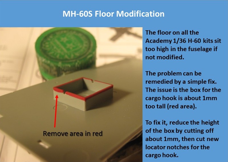
Step 12: Before proceeding to close up the fuselage, you will need to reduce the height of the box for the cargo hook on the underside of the floor. It needs to be reduced by about 1mm to allow the floor to sit correctly in the fuselage. This is outlined in red in the picture to the right. Once the height is reduced, cut new slots for the cargo hook to sit in. Proceed with placing the interior in the fuselage as shown. As a tip, I attach the gunners sidewalls to the fuselage first, then I glue the floor to the rear wall and the ceiling to the rear wall. Lastly, I place this assembly into the fuselage sandwiching it between the gunners sidewalls. This keeps the gunners sidewalls in the right place and allows the interior to settle into the fuselage easily as well. Also, I do not capture the tail rotor inside the fuselage either, again so it can be removed for transport or storage. I cut the mushroomed end off of the post (B51) and then glue the post to the tail rotor. This allows the tail rotor to be removed as needed. Build the engine intakes and exhausts as shown. I deviated here as well by not building the full exhausts since I would be using the Eduard exterior set FOD (Foreign Objects and Debris) covers on the engines. I left off parts D20 and cut the exhausts down since I will only be using the rear 1/2 inch of them.
Step 13: Build as shown. I left the exhausts off so they could be painted separately.
Step 14: Build as shown. Here you need to make a couple modifications though. On the top, forward hydraulics cowling (B52), there is an intake screen on the right side. This should be filled in as it is not present on the naval version. There are also two hand holds that need to be added to this part. There is one on each side near the top, rear edge. These are represented by Academy as decals; they are the laying on its back D part of decal 129 and 130 for option 1. I cut these out on part B52, backing them with sheet styrene, to represent the open hand holds better. Lastly, the naval version has two circular hand holds on the forward part of the main rotor cowl just forward of the circular rotor opening. I drilled these out using a 1/8 drill bit. I also drilled out the opening on the APR-144 disco ball sensor mount (D70) with a 1/4 drill bit.
Step 15: Assemble as shown. Also, the rear cargo doors should have a half-circle cut out on the upper, forward edge. I cut these out and added corresponding pieces on the fuselage where the openings make contact with the forward frame.
Step 16: Assemble as shown, with the following exception; leave off parts D8 and D9. If these are installed, neither the ESSS (External Stores Support System) wings (K32 - K34) nor the covers (D39, D40) will fit properly and there will be a large gap where they meet the sides of the fuselage. Add a piece of 0.030 sheet styrene to the position D39 and D40 are shown attaching that is the width of the pillar and about 1.5mm tall. This will close the area up after the ESSS wings or covers are installed and you will not have a gap.
Step 17: Select the parts to remove corresponding to the version you are building. Also select your options that correspond to your version.
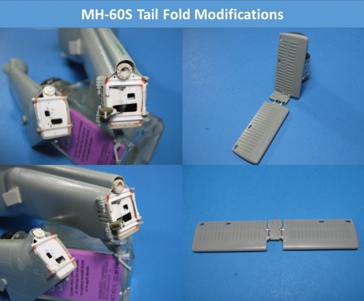
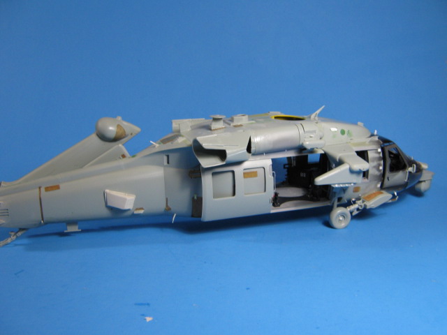
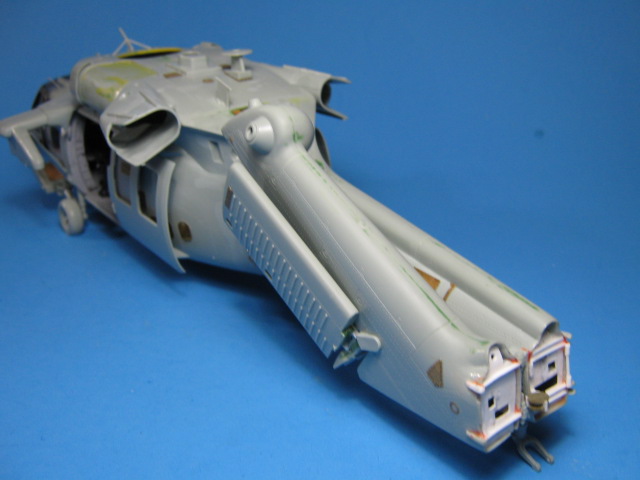
Step 18: This is where I cut the tail section off to build the folded tail. Cut along the diagonal line that the hinges are shown being attached over (just behind the vents w/three horizontal bars on them) and then follow the vertical line through the tail rotor shaft cover. Once I had the two parts separated, I thinned the inner surfaces down to look like sheet metal as opposed to thick plastic. I then made bulkheads out of thin sheet styrene. I detailed them with C channel and sheet styrene following reference pictures. I made the coupling gear for the tail rotor from small gears from old watches that I disassembled and kept when they stopped working. You never know when you can use a small gear. For the hinges, I took the kit parts and cut them apart into separate hinge parts and then glued them on each side where they go. Some 0.015 solder for hydraulic lines, thin wire for cabling, and guide wheels with steel-colored thred for the control wires finished it off. I also cut the two tail stabilator apart where the sides fold up. I filled the openings with filler putty and added hinge details to allow them to fold up as well. Also, you have to decide if you are adding the ESSS wings at this time or their covers so you can choose the corresponding lower landing gear shroud parts. Lastly, do not add the weapons as shown as they are incorrect for an MH-60S, as mentioned earlier.
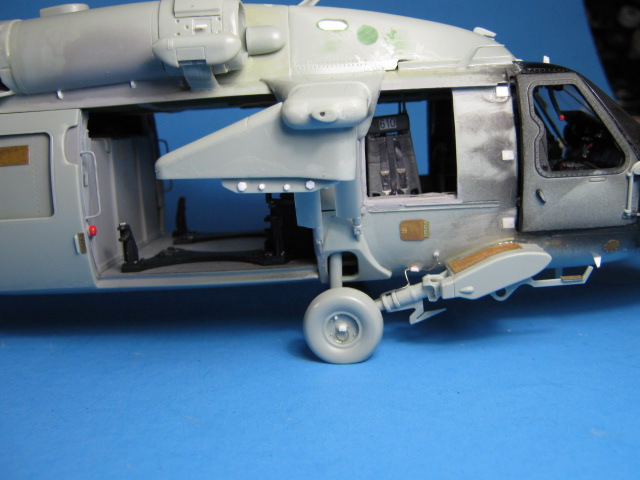
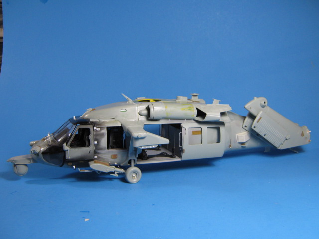
Step 19: Choose the correct step-sponsons for the version you are building and assemble the main landing gear arms and mounts as shown. Also, leave off the step/tie-down parts (a-15) on the underside of each sponson as the ones on an MH-60S are different. I made new steps for the pilots by squashing and bending thick solder into a laid back L shaped step and attaching them to the step sponsons on each side.
Step 20: Assemble the ESSS wings and supports or their covers depending on your version. Also, add the step-sponsons and landing gear that correspond to your version as you built them in step 19. Attach only part B59 (transmission) from the main rotor head so it can still be removed. Select the proper nose sensors for your version and attach them as shown. Lastly, the weapons are shown being attached to the ESSS pylons at this time, however, I leave them loose and attach them after painting since they are painted differently than the fuselage. Also of note, the painting instructions call for the Hellfire missiles to be painted OD green. This is incorrect, they should be flat black.
At this point, since the fuselage is complete, I added the exterior PE by Eduard. It is very complete and adds lots of details. I highly recommend it.
I also made a couple corrections on the fuselage. On the left side behind the exhaust, there is a circular depression that represents the Auxiliary Power Unit (APU generator) exhaust. This opening is in the wrong place as it is too far aft. I filled the depression and drilled a new hole in the correct place just under the rear edge of the exhaust opening, forward of the rectangular opening. I added a piece of thinned 1/8 tubing to represent the exhaust itself. Also, not incorrect, but lacking detail is the oval opening on the top of the left exhaust. I cut this open and added another piece of thinned 1/8 tubing cut on an angle to represent this part.
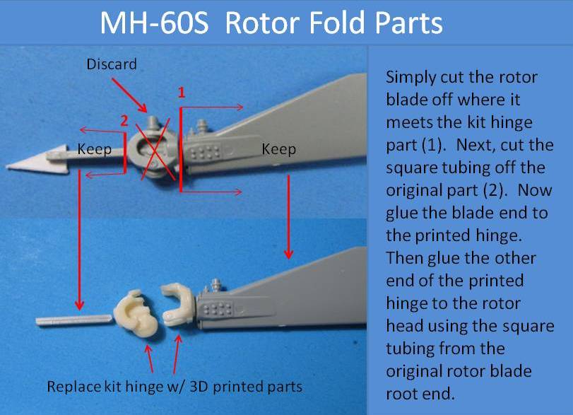
Pretty much all that was left for assembly was the folded rotor blades. The kit parts are molded in the open position and are lacking details. I first tried to make my own hinges using the kit ones. Once I cut them up and made a reasonable facsimile, I was left with one operating hinge, but it took me two kit hinges to make it. So I planned on casting more hinges in resin, which I tried. They did not come out too well. That is when I approached our own Matt Leese about making a CAD set of hinges that could be 3D printed at Shapeways to facilitate the hinge fold. Matt was able to design the hinges perfectly. They look and act just like the real one. I am very happy with them and they are easy to use. They are a simple swap out of the kit blade root end. First cut the rotor blade off where it meets the kit hinge part, then glue the blade to the printed hinge. Glue the other end of the printed hinge to the rotor head using a piece of round rod at the rotor blade root end. I chose a piece of plastic-covered metal rod for strength. There is a depression in the printed part to accept the rod. Once the rod is dry on the rotor head hinge part, attach the hinges to the head. Make sure the two front ones are first in the right direction with both hinges opening back (wheels on the outside). Second, be sure to glue the front two with a slight downward twist so they clear the back two. On the back two hinge positions, they should both also open back (wheels on the inside) so all the rotors fold toward the rear. These two can be glued pretty much straight and level with the rotor head. After the hinges are dry, you can glue the blades into place. Once the rotor blades were set in their folded positions, I plumbed the rotor head with a multitude of thin wires to represent all the cabling required for the folding naval rotor head. Again, I used thin solder and telephone wires for this, all painted black. It has a bunch of wires and this method captures their look well. I also added wires to the tail rotor head as required.
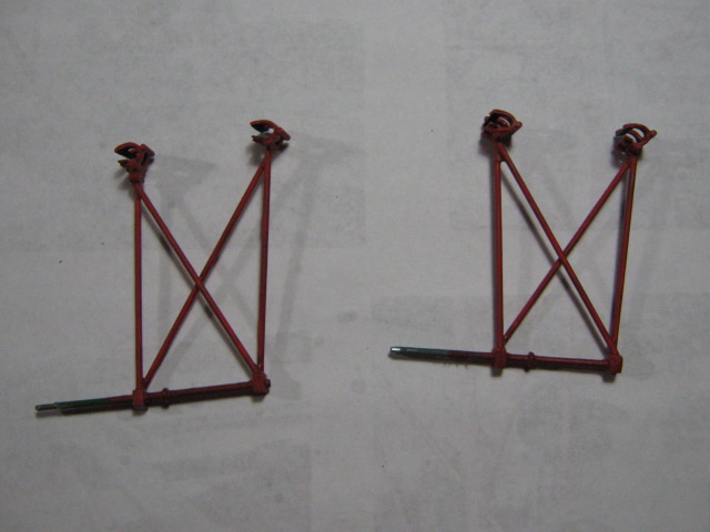
At this point, I also scratch-built the folded blade support rods out of metal and plastic rod and sheet styrene. I first drilled two 1/8 holes in the starboard side of the tail where the supports enter the fuselage. I then slid a piece of 1/8 tubing inside the hole and glued them in place. These are to accept the horizontal section of the blade supports, which I again used a plastic-covered metal rod for extra support. I then built the blade grips using cut sections of 1/4 plastic tubing which was cut into a C shape and then flattened, two pieces per grip. The two Cs were connected using small strips of sheet styrene and detailed using plastic a rod and half-round rod sections for the hinge and locking mechanism. Next I cut plastic blocks to make the attachment points for the vertical support rods. These were drilled where the rods attach and a hole drilled through them so they could slide onto the horizontal bar. Once the length of the rods were determined by holding them up to the rotor blades, each was cut and attached to the attachment blocks and the grips were glued on the other ends. Once all had dried, the supports were painted red and the grips were detailed with black for rubber where they touch the blades.
A note on the rotor fold: This method of folding the rotors is not 100% accurate, but will get you close and they look pretty correct. The actual H-60 naval rotor head is very different from the US Army/USAF version as in this kit. Academy did not fully update the rotor head.
About the Author


FROM: FLORIDA, UNITED STATES
Retired US Army Artillery Officer, currently a contractor at MacDill AFB in the Tampa, FL area. I have been modelling for the past 40+ years, really seriously on armor and large scale helos (1/32, 1/35) for the last 35 or so.
Comments
Great job and review Gino! I have this kit at home and have been adding a few more 1/35 scale helos. Looks like I will be giving Chris at CC another order soon!
NOV 11, 2015 - 11:27 PM
Thanks Jeff. I really enjoyed this one. Chris' products are great. You will really like them.
NOV 12, 2015 - 01:35 AM


Now that's a build story!!!
I hope that one day, I will reach this level (although doubting)
NOV 24, 2015 - 02:01 AM
Thanks Drabslab. I'm sure you could do a great job on one as well.
NOV 24, 2015 - 06:40 AM
I was reading this last week and then lo and behold, someone had it at a show Saturday for $35! Obviously had to grab it. With what I saved I guess I'll be picking up a few detail sets.
DEC 06, 2015 - 05:55 PM
Good luck on it. It can become a great model. I highly recommend the Shapeways printed rotor hinges, by our own Matt Leese. The folded rotors (and tail) really save on the space it can take up.
DEC 06, 2015 - 08:35 PM
Copyright ©2021 by Gino P. Quintiliani. Images also by copyright holder unless otherwise noted. The views and opinions expressed herein are solely the views and opinions of the authors and/or contributors to this Web site and do not necessarily represent the views and/or opinions of AeroScale, KitMaker Network, or Silver Star Enterrpises. Images also by copyright holder unless otherwise noted. Opinions expressed are those of the author(s) and not necessarily those of AeroScale. All rights reserved. Originally published on: 2015-11-11 01:20:51. Unique Reads: 16361

WEB HOSTING BY


Copyright ©2021 AeroScale and Kitmaker Network, a subsidiary of Silver Star Enterprises
All Rights Reserved. Please read our Conditions of Use and Privacy Policy.
All Rights Reserved. Please read our Conditions of Use and Privacy Policy.